Current Consumption for a Polling Receiver - Server application notes
Current Consumption for a Polling Receiver - Server application notes
Current Consumption for a Polling Receiver - Server application notes

You also want an ePaper? Increase the reach of your titles
YUMPU automatically turns print PDFs into web optimized ePapers that Google loves.
Design Note DN111<strong>Current</strong> <strong>Consumption</strong> <strong>for</strong> a <strong>Polling</strong> <strong>Receiver</strong>By Siri Johnsrud and Hung LiKeywords• Wake On Radio• Sleep Timer• CC1100• CC1101• CC1110Fx• CC1111Fx• CC2500• CC2510Fx• CC2511Fx1 IntroductionThe purpose of this design note is to showhow to optimize the current consumption<strong>for</strong> a polling receiver based on some of thedigital features of the CC1100 [1], CC1101 [2]and CC2500 [3], such as WOR and RSSI.The design note will also show how apolling receiver can be implemented usingthe CC1110/CC1111Fx [4] andCC2510/CC2511Fx [5]. This design note willassume that the reader is familiar with theWOR functionality of the CC1100, CC1101and CC2500. Details on WOR can befound in AN047 [6]. The currentconsumption plots shown throughout thisdocument are obtained frommeasurements done on the CC2500 andthe CC2510Fx, but will look similar <strong>for</strong> theCC1100, CC1101, and the CC1110Fx (the RXcurrent consumption will be different). Beaware that there are only done a couple ofmeasurements on each data rate. Thismeans that the average currentconsumption given in this document is notnecessarily typical values. The values aresimply given to provide a betterunderstanding on how differentparameters affect the currentconsumption.SWRA207 Page 1 of 40
Design Note DN111Table of ContentsKEYWORDS.............................................................................................................................. 11 INTRODUCTION............................................................................................................. 12 ABBREVIATIONS........................................................................................................... 23 SYSTEM OVERVIEW ..................................................................................................... 33.1 RX PERIOD ............................................................................................................... 33.2 LIMITATIONS .............................................................................................................. 34 TEST CASES.................................................................................................................. 45 CC2500 ........................................................................................................................... 55.1 RADIO CONFIGURATION FOR CC2500......................................................................... 55.1.1 Register Settings <strong>for</strong> the Different CC2500 Test Cases (Test Case 1 - 6) ........................55.2 MEASUREMENTS........................................................................................................ 65.2.1 Test Case 1 .......................................................................................................................75.2.2 Test Case 2 .......................................................................................................................95.2.3 Test Case 3 .....................................................................................................................115.2.4 Comparing Test Case 1, 2, and 3 ...................................................................................135.2.5 Test Case 4 .....................................................................................................................145.2.6 Test Case 5 .....................................................................................................................155.2.7 Test Case 6 .....................................................................................................................185.2.8 Comparing Test Case 4, 5, and 6 ...................................................................................216 CC2510 ......................................................................................................................... 226.1 CONFIGURING THE CC2510 ..................................................................................... 226.2 RADIO CONFIGURATION FOR CC2510....................................................................... 246.2.1 Register Settings <strong>for</strong> the Different CC2510 Test Cases (Test Case 7 - 12) ....................256.3 MEASUREMENTS...................................................................................................... 266.3.1 Test Case 7 .....................................................................................................................276.3.2 Test Case 8 .....................................................................................................................286.3.3 Test Case 9 .....................................................................................................................296.3.4 Comparing Test Case 7, 8, and 9 ...................................................................................306.3.5 Test Case 10 ...................................................................................................................316.3.6 Test Case 11 ...................................................................................................................326.3.7 Test Case 12 ...................................................................................................................336.3.8 Comparing Test Case 10, 11, and 12 .............................................................................347 CC2500 VS. CC2510 .................................................................................................... 358 CONCLUSION .............................................................................................................. 389 REFERENCES.............................................................................................................. 3910 GENERAL INFORMATION .......................................................................................... 4010.1 DOCUMENT HISTORY................................................................................................ 402 AbbreviationsHSPM{n}RSSISoCWORXOSCHigh SpeedPower Mode nReceived Signal Strength IndicatorSystem on Chip (in this document, used <strong>for</strong> CC1110Fx/CC1111Fxand CC2510Fx/CC2511Fx)Wake On RadioCrystal OscillatorSWRA207 Page 2 of 40
Design Note DN111• The current consumption of the MCU both in low power mode (while waiting <strong>for</strong> apacket) and in active mode (while processing the packet) <strong>for</strong> the CC2500 case, andthe method of reception used on the CC2510Fx (DMA, interrupt, polling)• Processing time <strong>for</strong> the incoming packets• Data rate (only two different data rates are used in this design note)4 Test Cases12 different test cases are discussed throughout this document; 6 <strong>for</strong> the CC2500 and 6 <strong>for</strong> theCC2510Fx. Table 2 lists the different test cases.TestCase #CC2500TestCase #CC2510Fx7 The RX strobe is issued 350 µs 2 after1 The RX strobe is issued 346.2 µs 1 afterThe radio stays in RX <strong>for</strong> 31.25 ms 1 The radio stays in RX <strong>for</strong> 31.25 ms 1exiting SLEEP state.The PLL is calibrated when going fromIDLE to RX.exiting PM2.The PLL is calibrated when going fromIDLE to RX.8 The RX strobe is issued 350 µs 2 after2 The RX strobe is issued 173.1 µs 1 afterThe radio stays in RX <strong>for</strong> 31.25 ms 1 The radio stays in RX <strong>for</strong> 31.25 ms 1exiting SLEEP stateThe PLL is not calibrated when goingfrom IDLE to RX.exiting PM2.The PLL is not calibrated when goingfrom IDLE to RX.9 The RX strobe is issued 350 µs 2 after3 The RX strobe is issued 173.1 µs 1 afterThe radio stays in RX <strong>for</strong> ~246 µs 3 The radio stays in RX <strong>for</strong> ~246 µs 3exiting SLEEP state.The PLL is not calibrated when goingfrom IDLE to RX.exiting PM2.The PLL is not calibrated when goingfrom IDLE to RX.10 The RX strobe is issued 350 µs 2 after4 The RX strobe is issued 346.2 µs 1 afterThe radio stays in RX <strong>for</strong> 1.95 ms 1 The radio stays in RX <strong>for</strong> 1.95 ms 1exiting SLEEP state.The PLL is calibrated when going fromIDLE to RX.exiting PM2.The PLL is calibrated when going fromIDLE to RX.11 The RX strobe is issued 350 µs 2 after5 The RX strobe is issued 173.1 µs 1 afterThe radio stays in RX <strong>for</strong> 1.95 ms 1 The radio stays in RX <strong>for</strong> 1.95 ms 1exiting SLEEP state.The PLL is not calibrated when goingfrom IDLE to RX.exiting PM2.The PLL is not calibrated when goingfrom IDLE to RX.12 The RX strobe is issued 350 µs 2 after6 The RX strobe is issued 173.1 µs 1 afterThe radio stays in RX <strong>for</strong> ~89 µs 3 The radio stays in RX <strong>for</strong> ~133 µs 3exiting SLEEP state.The PLL is not calibrated when goingfrom IDLE to RX.exiting PM2.The PLL is not calibrated when goingfrom IDLE to RX.Table 2. Test Cases1 See Table 32 PM2 to Active: ~100 µs, HS XOSC start-up time: ~250 µs3 See DN505 [8]SWRA207 Page 4 of 40
Design Note DN1115 CC25005.1 Radio Configuration <strong>for</strong> CC2500For both data rates, preferred settings (optimized <strong>for</strong> sensitivity) from SmartRF Studio [7],version 6.9.2.0, are used, with some modifications; PKTLEN = 0x3D (to avoid overflow of theRXFIFO) and IOCFG2 = 0x2E. Three other registers are modified <strong>for</strong> the different test cases,and these registers are MCSM0, WORCTRL, and MCSM2 (see Table 3 <strong>for</strong> details).Register Register Field CommentMCSM0FS_AUTOCALPO_TIMEOUT01 The PLL is calibrated every time be<strong>for</strong>e the radio enters RX mode.00 The PLL is not being calibrated (manual calibration must be per<strong>for</strong>med ata given time interval depending on the environment the system operatesin)00 CHP_RDYn is asserted 2.4 µs after the crystal is stable(CHP_RDYn is asserted 150 µs + 2.4 µs = 152.4 µs after the chip exitSLEEP state → EVENT1 should be 001 or higher)10 CHP_RDYn is asserted 155.1 µs after the crystal is stable(CHP_RDYn is asserted 150 µs + 155.1 µs = 305.1 µs after the chip exitSLEEP state → EVENT1 should be 011 or higher)WORCTRLMCSM2EVENT1RX_TIME_RSSIRX_TIME001 t Event1 = 173.1 µs011 t Event1 = 346.2 µs0 Radio will go back to SLEEP when the RX timeout expires1 Radio will go back to SLEEP if the RSSI level is below a certainthreshold. Please see DN505 [8] <strong>for</strong> details on how to estimate this time<strong>for</strong> the different register settings.010 Duty cycle = 3.125% and hence RX timeout = 31.25 ms (used when thedata rate is 10 kBaud, since minimum RX timeout is 20.8 ms (see Section3)).110 Duty cycle = 0.195% and hence RX timeout = 1.95 ms (used when thedata rate is 250 kBaud, since minimum RX timeout is 832 µs (see Section3)).Table 3. Registers Modified <strong>for</strong> the Different Test Cases (1 - 6)5.1.1 Register Settings <strong>for</strong> the Different CC2500 Test Cases(Test Case 1 - 6)Register settings <strong>for</strong> the different test cases are shown in Table 4.Data Rate [kBaud] Test Case # Register Reg. Setting Comment10123MCSM0 0x18 FS_AUTOCAL = 01PO_TIMEOUT = 10WORCTRL 0x38 EVENT1 = 011MCSM2 0x02 RX_TIME_RSSI = 0RX_TIME = 010MCSM0 0x00 FS_AUTOCAL = 00PO_TIMEOUT = 00WORCTRL 0x18 EVENT1 = 001MCSM2 0x02 RX_TIME_RSSI = 0RX_TIME = 010MCSM0 0x00 FS_AUTOCAL = 00PO_TIMEOUT = 00WORCTRL 0x18 EVENT1 = 001MCSM2 0x12 RX_TIME_RSSI = 1RX_TIME = 010SWRA207 Page 5 of 40
Design Note DN111250456MCSM0 0x18 FS_AUTOCAL = 01PO_TIMEOUT = 10WORCTRL 0x38 EVENT1 = 011MCSM2 0x06 RX_TIME_RSSI = 0RX_TIME = 110MCSM0 0x00 FS_AUTOCAL = 00PO_TIMEOUT = 00WORCTRL 0x18 EVENT1 = 001MCSM2 0x06 RX_TIME_RSSI = 0RX_TIME = 110MCSM0 0x00 FS_AUTOCAL = 00PO_TIMEOUT = 00WORCTRL 0x18 EVENT1 = 001MCSM2 0x16 RX_TIME_RSSI = 1RX_TIME = 110Table 4. Register Settings Test Case 1 – 6See Table 2 <strong>for</strong> a more detailed explanation of the different test cases.5.2 MeasurementsThe following pseudo code shows the program flow when measuring the currentconsumption. Code <strong>for</strong> handling incoming packets and entering low power mode on the MCUis not implemented and must be taken care of by the <strong>application</strong>.void main (void){// Init MCU// Reset Radio// Configure Radio// Calibrate the Radio// Enter WOR mode// Wait <strong>for</strong> a packet to be received}The average current consumption is given by Equation 1.<strong>Current</strong>AVG[ us]t=Active( ) ⋅<strong>Current</strong>[ uA][ us] ⋅ <strong>Current</strong>Active[ uA] + tpolling[ us] − tActive[ us]t [ us]pollingSLEEPwhere:Equation 1. Average <strong>Current</strong> <strong>Consumption</strong>t Active : The time the CC2500/CC2510Fx is not in SLEEP state/PM2<strong>Current</strong> Active : Average current consumption in the period where the radio is not inSLEEP state/PM2 modet <strong>Polling</strong> : The polling period t Event0 (1 s in this case)<strong>Current</strong> SLEEP : <strong>Current</strong> consumption when the CC2500/CC2510Fx is in SLEEP state/PM2 (thesenumbers are taken from the data sheets [3] and [5])From the oscilloscope the XY wave<strong>for</strong>m pairs were input to Excel <strong>for</strong> analysis. 2000 XY pairswhere analyzed, given a resolution of 25 µs (X-axis) in test case 1 - 3 and 2.5 µs in test case4 - 6.SWRA207 Page 6 of 40
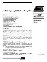
Design Note DN1115.2.1 Test Case 1Figure 2 shows the current consumption <strong>for</strong> the complete period of time when the CC2500 isnot in SLEEP state, while Figure 3 zooms in on the start of this period.RX timeout = 31.25 msAvg. current consumption when not in SLEEP: 16.95 mAThe time the radio is not in SLEEP is measured to be 32.525 msFigure 2. <strong>Current</strong> <strong>Consumption</strong> Test Case 1RXIDLE to RX w /calibration = 799 µst Event1 = 346.2 µsFigure 3. <strong>Current</strong> <strong>Consumption</strong> Test Case 1 (start-up sequence)SWRA207 Page 7 of 40
Design Note DN111This gives an average current consumption of( 1000000 − 32525)32525⋅16950+⋅ 0.9<strong>Current</strong> AVG== 552.2 uA1000000Using the Excel sheet (see Figure 4), the current consumption was estimated to be 548.4 µA,giving an error in the estimation of about 0.69%.Figure 4. Estimated <strong>Current</strong> <strong>Consumption</strong> <strong>for</strong> Test Case 1SWRA207 Page 8 of 40
Design Note DN111This gives an average current consumption of( 1000000 − 31625)31625⋅17190+⋅ 0.9<strong>Current</strong> AVG== 544.5 uA1000000Using the Excel sheet (see Figure 7), the current consumption was estimated to be 542.8 µA,giving an error in the estimation of about 0.31%.Figure 7. Estimated <strong>Current</strong> <strong>Consumption</strong> <strong>for</strong> Test Case 2SWRA207 Page 10 of 40
Design Note DN1115.2.3 Test Case 3Figure 8 shows the current consumption <strong>for</strong> the complete period of time when the CC2500 isnot in SLEEP state, while Figure 9 zooms in on the start of this period.RX terminated after ~260 us since theRSSI value is below threshold (seeDN505 [8])Avg. current consumption when not in SLEEP: 4.12 mARadio will stay in IDLE to complete thecalibration of the RCOSC be<strong>for</strong>e returningto SLEEP (see AN047 [6])The time the radio is not in SLEEP is measured to be 1.85 msFigure 8. <strong>Current</strong> <strong>Consumption</strong> Test Case 3RXIDLE to complete calibration of RCOSC (see AN047 [6])IDLE to RX withoutcalibration = 75.1 µst Event1 = 173.1 µsFigure 9. <strong>Current</strong> <strong>Consumption</strong> Test Case 3 (start-up sequence)SWRA207 Page 11 of 40
Design Note DN111This gives an average current consumption of( 1000000 −1850)4120 ⋅1850+⋅ 0.9<strong>Current</strong> AVG== 8.5 uA1000000Using the Excel sheet (see Figure 10), the current consumption was estimated to be 9.2 µA,giving an error in the estimation of about −7.61%.Figure 10. Estimated <strong>Current</strong> <strong>Consumption</strong> <strong>for</strong> Test Case 3The error in the estimation is mainly due to the time it takes to calibrate the RCOSC. TheExcel sheet sets the calibration time to be 2 ms while it was measured to be 1.625 ms in testcase 3. Changing this number (C46 changed to 1625), the estimated current consumption is8.6 µA (see Figure 11), giving an error in the estimation of about −1.16%.Figure 11. Estimated <strong>Current</strong> <strong>Consumption</strong> <strong>for</strong> Test Case 3 (C46 changed to 1625)SWRA207 Page 12 of 40
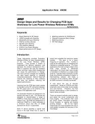
Design Note DN1115.2.4 Comparing Test Case 1, 2, and 3Figure 12 and Figure 13 shows the three test cases 1 - 3 in the same plot. Test case 2 haslower current consumption than test case 1 due to lack of calibration of the PLL, while testcase 3 has much lower current consumption than the other two due to significantly reducedtime spent in RX.10 kBaud20181614<strong>Current</strong> <strong>Consumption</strong> [mA]121086Test Case 1Test Case 2Test Case 3420TimeFigure 12. Test Case 1 - 310 kBaud201816<strong>Current</strong> <strong>Consumption</strong> [mA]14121086Test Case 1Test Case 2Test Case 34200 0,5 1 1,5Time [ms]Figure 13. Test Case 1 - 3 (start-up sequence)SWRA207 Page 13 of 40
Design Note DN1115.2.5 Test Case 4Figure 14 shows the current consumption <strong>for</strong> the complete period of time when the CC2500 isnot in SLEEP state.RX timeout = 1.95 mst Event1 = 346.2 µsAvg. current consumption when not inSLEEP: 13.06 mAIDLE to RX w /calibration = 799 µs150 µs in IDLE state be<strong>for</strong>e enteringSLEEP (see AN047 [6])The time the radio is not in SLEEP is measured to be 3.245 msFigure 14. <strong>Current</strong> <strong>Consumption</strong> Test Case 4This gives an average current consumption of( 1000000 − 3245)3245⋅13060+⋅ 0.9<strong>Current</strong> AVG== 43.3 uA1000000Using the Excel sheet (see Figure 15), the current consumption was estimated to be 44.3 µA,giving an error in the estimation of about −2.26%.SWRA207 Page 14 of 40
Design Note DN111Figure 15. Estimated <strong>Current</strong> <strong>Consumption</strong> <strong>for</strong> Test Case 4The error in the estimation is mainly due to the RX current consumption. The Excel sheet setsthis to be 18.8 mA, while it was measured to be 18.4 mA in test case 4. If this current ischanged (F7 changed to 18400), the estimated current consumption is43.5 µA (see Figure 16), giving an error in the estimation of about −0.46%....Figure 16. Estimated <strong>Current</strong> <strong>Consumption</strong> <strong>for</strong> Test Case 4 (F7 changed to 18400)5.2.6 Test Case 5Figure 17 shows the current consumption <strong>for</strong> the complete period of time when the CC2500 isnot in SLEEP state.SWRA207 Page 15 of 40
Design Note DN111RX timeout = 1.95 msAvg. current consumption when not inSLEEP: 15.5 mAt Event1 = 173.1 µsIDLE to RX without calibration = 75.1 µs150 µs in IDLE state be<strong>for</strong>e enteringSLEEP (see AN047 [6])The time the radio is not in SLEEP is measured to be 2.36 msFigure 17. <strong>Current</strong> <strong>Consumption</strong> Test Case 5This gives an average current consumption of( 1000000 − 2360)2360 ⋅15500+⋅ 0.9<strong>Current</strong> AVG== 37.5 uA1000000Using the Excel sheet (see Figure 18), the current consumption was estimated to be 38.7 µA,given an error in the estimation of about −3.1%.SWRA207 Page 16 of 40
Design Note DN111Figure 18. Estimated <strong>Current</strong> <strong>Consumption</strong> <strong>for</strong> Test Case 5Also in this case, the error in the estimation is mainly due to the RX current consumption (seeSection 5.2.5). Setting it to 18.4 mA instead of 18.8 mA, the estimated current consumptionwill be 37.9 µA (see Figure 19), giving an error in the estimation of about −1.06%.Figure 19. Estimated <strong>Current</strong> <strong>Consumption</strong> <strong>for</strong> Test Case 5 (F7 changed to 18400)SWRA207 Page 17 of 40
Design Note DN1115.2.7 Test Case 6Figure 20 shows the current consumption <strong>for</strong> the complete period of time when the CC2500 isnot in SLEEP state.t Event1 = 173.1 µsRX terminated after ~100 µs since theRSSI value is below threshold (seeDN505 [8])IDLE to RX withoutcalibration = 75.1 µsAvg. current consumption when not inSLEEP: 2.95 mARadio will stay in IDLE to complete thecalibration of the RCOSC be<strong>for</strong>e returningto SLEEP (see AN047 [6])The time the radio is not in SLEEP is measured to be 1.83 msFigure 20. <strong>Current</strong> <strong>Consumption</strong> Test Case 6This gives an average current consumption of( 1000000 −1830)1830 ⋅ 2950 +⋅ 0.9<strong>Current</strong> AVG== 6.3 uA1000000Using the Excel sheet (see Figure 21), the current consumption was estimated to be 6.6 µA,given an error in the estimation of about −4.55%.SWRA207 Page 18 of 40
Design Note DN111Figure 21. Estimated <strong>Current</strong> <strong>Consumption</strong> <strong>for</strong> Test Case 6The error in the estimation is mainly due to the time it takes to calibrate the RCOSC inaddition to the IDLE current consumption. The Excel sheet sets the calibration time to be 2ms and the IDLE current consumption to 1.5 mA while it was measured to be 1.625 ms and1.7 mA respectively. Changing these numbers (C46 changed to 1600 and F4 changed to1700, in addition to changing the RX current consumption as in Test Case 4 and 5), theestimated current consumption is 6.3 µs (see Figure 22).SWRA207 Page 19 of 40
Design Note DN111Figure 22. Estimated <strong>Current</strong> <strong>Consumption</strong> <strong>for</strong> Test Case 6 (F7 changed to 18400, F4changed to 1700, and C46 changed to 1625)SWRA207 Page 20 of 40
Design Note DN1115.2.8 Comparing Test Case 4, 5, and 6Figure 23 shows the three test cases 4 - 6 in the same plot. The result is the same asdiscussed in Section 5.2.4 (test case 4 corresponds to test case 1, 5 to 2, and 6 to 3respectively).250 kBaud201816<strong>Current</strong> <strong>Consumption</strong> [mA]14121086Test Case 4Test Case 5Test Case 642000,10,20,30,40,50,60,70,80,911,11,21,31,41,51,61,71,81,922,12,22,32,42,52,62,72,82,933,13,2Time [ms]Figure 23. Test Case 4 - 6SWRA207 Page 21 of 40
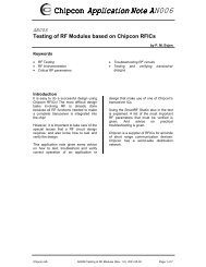
Design Note DN1116 CC25106.1 Configuring the CC2510To be able to reduce the power consumption on the CC2510, the system clock speed shouldbe reduced from its max value, f XOSC (26 MHz). Be aware that reducing the system clockspeed not only reduces the current consumption, but also increases the transition timesbetween different radio states (see DN110 [10] <strong>for</strong> more details).PM2 to RX with Calibration (system clock running at different speeds)<strong>Current</strong> <strong>Consumption</strong>Series1Series2Series3TimeFigure 24. PM2 to RX with Calibration (system clock running at different speeds)Figure 24 shows the current consumption when waking up from PM2 and entering RX state.The program flow <strong>for</strong> the three different series is shown in Table 5.Series123DescriptionWake up from PM2 and turn on the HSXOSC (system clock speed set to 26 MHz)Strobe RXEnter PM0 (CPU is halted)Wake up from PM2 and turn on the HSXOSC (system clock speed set to 203.125 kHz)Strobe RXEnter PM0 (CPU is halted)Wake up from PM2 and turn on the HSXOSC (system clock speed set to 26 MHz)Strobe RXWait <strong>for</strong> radio to enter RX state (MARCSTATE = 0x0D)Change system clock speed to 203.125 kHzEnter PM0Table 5. Pseudo Code <strong>for</strong> Test Code running when generating the <strong>Current</strong> <strong>Consumption</strong>Plots shown in Figure 24From Figure 24 one can see that even if the RX current consumption is reduced when thesystem clock speed is 203.125 kHz (series2) compared to when it is 26 MHz (series1), thetransition time is about 10 times as long, and hence the average current consumption willincrease instead of decrease when reducing the system clock speed. A solution will be to letthe system clock run at 26 MHz until RX state is reached and the turn it down to 203.125 kHz(series3). Even if both series1 and series3 have the system clock speed set to 26 MHz duringthe transition to RX state, series3 will have higher current consumption during the transition,since the CPU must be in active mode to poll MARCSTATE instead of being halted (PM0), likeis the case with series1.SWRA207 Page 22 of 40
Design Note DN111Figure 25 shows how the currents consumption decreases and the transition time increaseswith decreasing system clock speed.PM2 to RX with Calibration (system clock running at different speeds be<strong>for</strong>e entering RX state)<strong>Current</strong> <strong>Consumption</strong>26 MHz13 MHz6.5 MHz3.25 MHz1.625 Mhz812.5 kHz406.25 kHz203.125 kHzTimeFigure 25. PM2 to RX with Calibration (different system clock speeds used be<strong>for</strong>e enteringRX mode)Since the RX time is constant, as is the polling interval, the system with the longest transitiontime will be the one that spends the least time in PM2. Analyzing the above current plot inExcel shows that running the system clock at 13 MHz until RX state is reached and thenswitch to 203.125 kHz will be the best solution when trying to reduce the current consumptionas much as possible (running the system clock at 26 MHz gives a slightly higher currentconsumption). However, it is not necessarily the case that running the system clock at 13MHz and then reduce it to 203.125 kHz will always give the lowest current consumption.Figure 26 shows the case where no calibration is per<strong>for</strong>med when going from IDLE to RX andRX state is terminated if the RSSI is below a certain threshold. In this particular case, runningthe system clock at 26 MHz be<strong>for</strong>e RX mode is entered gives a lower current consumptionthan if the system clock runs at 13 MHz.SWRA207 Page 23 of 40
Design Note DN11126 MHz vs. 13 MHz when going from PM2 to RX (no calibration)<strong>Current</strong> <strong>Consumption</strong>26 MHz13 MHzTimeFigure 26. 26 MHz vs. 13 MHz when going from PM2 to RX without Calibration6.2 Radio Configuration <strong>for</strong> CC2510For both data rates, preferred settings (optimized <strong>for</strong> sensitivity) from SmartRF Studio [7] ,version 6.9.2.0, are used. Two other registers are modified <strong>for</strong> the different test cases, andthese registers are MCSM0 and MCSM2 (see Table 6 <strong>for</strong> details).Register Register Field CommentMCSM0MCSM2FS_AUTOCALRX_TIME_RSSIRX_TIME01 The PLL is calibrated every time be<strong>for</strong>e the radio enters RX mode00 The PLL is not being calibrated (manual calibration must be per<strong>for</strong>medat a given time interval depending on the environment the systemoperates in)0 Radio will go back to IDLE when the RX timeout expires1 Radio will go back to IDLE if the RSSI level is below a certain threshold.Please see DN505 [8] <strong>for</strong> details on how to estimate this time <strong>for</strong> thedifferent register settings010 Duty cycle = 3.125% and hence RX timeout = 31.25 ms (used when thedata rate is 10 kBaud, since minimum RX timeout is 20.8 ms (seeSection 3)).110 Duty cycle = 0.195% and hence RX timeout = 1.95 ms (used when thedata rate is 250 kBaud, since minimum RX timeout is 832 µs (seeSection 3)).Table 6. Registers Modified <strong>for</strong> the Different Test Cases (7 - 12)SWRA207 Page 24 of 40
Design Note DN1116.2.1 Register Settings <strong>for</strong> the Different CC2510 Test Cases(Test Case 7 - 12)Register settings <strong>for</strong> the different test cases are shown in Table 7.Data Rate [kBaud] Test Case # Register Reg. Setting Comment10250789101112MCSM0 0x14 FS_AUTOCAL = 01MCSM2 0x02 RX_TIME_RSSI = 0RX_TIME = 010MCSM0 0x04 FS_AUTOCAL = 00MCSM2 0x02 RX_TIME_RSSI = 0RX_TIME = 010MCSM0 0x04 FS_AUTOCAL = 00MCSM2 0x12 RX_TIME_RSSI = 1RX_TIME = 010MCSM0 0x14 FS_AUTOCAL = 01MCSM2 0x06 RX_TIME_RSSI = 0RX_TIME = 110MCSM0 0x04 FS_AUTOCAL = 00MCSM2 0x06 RX_TIME_RSSI = 0RX_TIME = 110MCSM0 0x04 FS_AUTOCAL = 00MCSM2 0x16 RX_TIME_RSSI = 1RX_TIME = 110Table 7. Register Settings Test Case 7 - 12In test case 7 and 10 the system clock will run at 13 MHz until the radio is in RX state and willthen be switched to 203.125 kHz and 1.625 MHz 4 respectively. In test case 8, 9, 11, and 12(when FS_AUTOCAL=00) the system clock will run at 26 MHz until the radio reaches RX stateand then be switched to 203.125 kHz and 1.625 MHz 4 respectively. See Table 2 <strong>for</strong> a moredetailed explanation of the different test cases.4 When using a data rate of 10 kBaud (test case 7 - 9) the minimum system clock speed is203.125 kHz. When using 250 kBaud (test case 10 - 12), the minimum system clock speed is1.625 MHz. Please see the SoC data sheets ([4] and [5]) <strong>for</strong> more details.SWRA207 Page 25 of 40
Design Note DN1116.3 MeasurementsThe following pseudo code shows the program flow when measuring the currentconsumption. Code <strong>for</strong> handling incoming packets is not implemented and must be takencare of by the <strong>application</strong>.void main (void){// Configure Radio// Calibrate the Radio// Turn on the HSXOSC and turn off the HSRCOSC (System clock running at// 13 MHz <strong>for</strong> test case 7 and 10 and at 26 MHz <strong>for</strong> test case 8, 9, 11, and 12)while (TRUE){// Enable RX timeout interrupt// Strobe RX// Wait <strong>for</strong> radio to enter RX state// Set system clock to run at 203.125 kHz (test case 7, 8, and 9) or 1.625// MHz (test case 10, 11, and 12)// Enter PM0 (continue from next line after an RX timeout interrupt occur)// Disable RX timeout interrupt and enable Sleep timer interrupt// Enter PM2 (this must be done according to DN106 [9])}}//--------------------------------------------------------------------------------#pragma vector=RF_VECTOR__interrupt void rf_IRQ(void){// Clear interrupt flag// Turn on the HSRCOSC and turn off the HSXOSC (System clock running at// 13 MHz)}//--------------------------------------------------------------------------------#pragma vector=ST_VECTOR__interrupt void st_IRQ(void){// Enable Flash Cache// Clear interrupt flags// Turn on the HSXOSC and turn off the HSRCOSC (System clock running at// 13 MHz <strong>for</strong> test case 7 and 10 and at 26 MHz <strong>for</strong> test case 8, 9, 11, and 12)// Disable Sleep timer interrupt// Clear the MODE bits}From the oscilloscope the XY wave<strong>for</strong>m pairs were input to Excel <strong>for</strong> analysis. 2000 XY pairswhere analyzed, given a resolution of 25 µs (X-axis) in test case 7 - 9 and 2.5 µs in test case10 - 12.SWRA207 Page 26 of 40
Design Note DN1116.3.1 Test Case 7Figure 27 shows the current consumption <strong>for</strong> the complete period of time when the CC2510Fxis not in PM2, while Figure 28 zooms in on the start of this period.RX timeout = 31.25 msAvg. current <strong>Consumption</strong> when not in PM2: 17.50 mAThe time the radio is not in PM2 is measured to be 32.975 msFigure 27. <strong>Current</strong> <strong>Consumption</strong> Test Case 7RXIDLE to RX w /calibration = 862 µsPM2 to Active Mode = 100 µsHSXOSC start-up = 250 µsFigure 28. <strong>Current</strong> <strong>Consumption</strong> Test Case 7 (start-up sequence)This gives an average current consumption of( 1000000 − 32975)32975⋅17500+⋅0.5<strong>Current</strong> AVG== 577.5 uA1000000SWRA207 Page 27 of 40
Design Note DN1116.3.2 Test Case 8Figure 29 shows the current consumption <strong>for</strong> the complete period of time when the CC2510Fxis not in PM2, while Figure 30 zooms in on the start of this period.RX timeout = 31.25 msAvg. current <strong>Consumption</strong> when not in PM2: 17.48 mAThe time the radio is not in PM2 is measured to be 32.150 msFigure 29. <strong>Current</strong> <strong>Consumption</strong> Test Case 8RXPM2 to Active Mode = 100 µsIDLE to RX without calibration = 75.1 µsHSXOSC start-up = 250 µsFigure 30. <strong>Current</strong> <strong>Consumption</strong> Test Case 8 (start-up sequence)This gives an average current consumption of( 1000000 − 32150)32150 ⋅17480+⋅ 0.5<strong>Current</strong> AVG== 562.5 uA1000000SWRA207 Page 28 of 40
Design Note DN1116.3.3 Test Case 9Figure 31 shows the current consumption <strong>for</strong> the complete period of time when the CC2510Fxis not in PM2, while Figure 32 zooms in on the start of this period.RX terminated after ~260 us since theRSSI value is below threshold (seeDN505 [8])Avg. current consumption when not in PM2: 5.66 mAThe CPU will stay in Active mode to complete thecalibration of the low power RCOSC be<strong>for</strong>ereturning to PM2The time the radio is not in PM2 is measured to be 2.100 msFigure 31. <strong>Current</strong> <strong>Consumption</strong> Test Case 9RXPM2 to Active Mode = 100 µsCPU in Active mode to complete calibration of the low powerRCOSCIDLE to RX withoutcalibration = 75.1 µsHSXOSC start-up = 250 µsFigure 32. <strong>Current</strong> <strong>Consumption</strong> Test Case 9 (start-up sequence)This gives an average current consumption of( 1000000 − 2100)2100 ⋅5660+⋅ 0.5<strong>Current</strong> AVG== 12.4 uA1000000SWRA207 Page 29 of 40
Design Note DN1116.3.4 Comparing Test Case 7, 8, and 9Figure 33 and Figure 34 shows the three test cases 7 - 9 in the same plot. Test case 8 haslower current consumption than test case 7 due to lack of calibration of the PLL, while testcase 9 has much lower current consumption than the other two due to significantly reducedtime spent in RX.10 kBaud20181614<strong>Current</strong> <strong>Consumption</strong> [mA]121086Test Case 7Test Case 8Test Case 9420TimeFigure 33. Test Case 7 - 910 kBaud201816<strong>Current</strong> <strong>Consumption</strong> [mA]14121086Test Case 7Test Case 8Test Case 94200 0,5 1 1,5Time [ms]Figure 34. Test Case 7 - 9 (start-up sequence)SWRA207 Page 30 of 40
Design Note DN1116.3.5 Test Case 10Figure 35 shows the current consumption <strong>for</strong> the complete period of time when the CC2510Fxis not in PM2.RX timeout = 1.95 msIDLE to RX w /calibration = 862 µsPM2 to Active Mode = 100 µsAvg. current consumption when not inPM2: 14.38 mAExecuting code <strong>for</strong> proper entering ofPM2. Turning on the HSRCOSC andturning off the HSXOSCHSXOSC start-up = 250 µsThe time the radio is not in PM2 is measured to be 3.345 msFigure 35. <strong>Current</strong> <strong>Consumption</strong> Test Case 10This gives an average current consumption of( 1000000 − 3345)3345⋅14380+⋅ 0.5<strong>Current</strong> AVG== 48.6 uA1000000SWRA207 Page 31 of 40
Design Note DN1116.3.6 Test Case 11Figure 36 shows the current consumption <strong>for</strong> the complete period of time when the CC2510Fxis not in PM2.RX timeout = 1.95 msAvg. current consumption when not inPM2: 15.50 mAIDLE to RX without calibration = 75.1 µsPM2 to Active Mode = 100 µsExecuting code <strong>for</strong> proper entering ofPM2. Turning on the HSRCOSC andturning off the HSXOSCHSXOSC start-up = 250 µsThe time the radio is not in PM2 is measured to be 2.553 msFigure 36. <strong>Current</strong> <strong>Consumption</strong> Test Case 11This gives an average current consumption of( 1000000 − 2553)2553⋅15500+⋅ 0.5<strong>Current</strong> AVG== 40.1uA1000000SWRA207 Page 32 of 40
Design Note DN1116.3.7 Test Case 12Figure 37 shows the current consumption <strong>for</strong> the complete period of time when the CC2510Fxis not in PM2.RX terminated after ~120 us since theRSSI value is below threshold (seeDN505 [8])Avg. current consumption when not inPM2: 5.24 mAIDLE to RX without calibration = 75.1 µsPM2 to Active Mode = 100 µsCPU in Active mode to completecalibration of the low power RCOSCHSXOSC start-up = 250 µsThe time the radio is not in PM2 is measured to be 2.06 msFigure 37. <strong>Current</strong> <strong>Consumption</strong> Test Case 12This gives an average current consumption of( 1000000 − 2060)2060 ⋅ 5240 +⋅ 0.5<strong>Current</strong> AVG== 11.3 uA1000000SWRA207 Page 33 of 40
Design Note DN1116.3.8 Comparing Test Case 10, 11, and 12Figure 38 shows the three test cases 10 - 12 in the same plot. The result is the same asdiscussed in Section 6.3.4 (test case 10 corresponds to test case 7, 11 to 8, and 12 to 9respectively).250 kBaud201816<strong>Current</strong> <strong>Consumption</strong> [mA]14121086Test Case 10Test Case 11Test Case 1242000,10,20,30,40,50,60,70,80,911,11,21,31,41,51,61,71,81,922,12,22,32,42,52,62,72,82,933,13,23,3Time [ms]Figure 38. Test Case 10 - 12SWRA207 Page 34 of 40
Design Note DN1117 CC2500 vs. CC2510Table 8 shows a comparison between two different solutions <strong>for</strong> implementing a pollingreceiver. One solution is using a transceiver in WOR mode (in this case the CC2500) and theother solution is to use the Sleep Timer of a SoC (in this case CC2510Fx). As we can see, thecurrent consumption seems a little bit higher on the SoC solution, but have in mind that <strong>for</strong>the transceiver solution, the current consumption of the MCU will be in addition to thenumbers shown in Table 8. Please also note that the numbers represented here are nottypical numbers as only a few measurements have been done.CC2500CC2510FxData Rate [kBaud]10250TestCaseAvg. <strong>Current</strong><strong>Consumption</strong> [µA]TestCase1 552.2 7 577.52 544.5 8 562.53 8.5 9 12.44 43.3 10 48.65 37.7 11 40.16 6.3 12 11.3Avg. <strong>Current</strong><strong>Consumption</strong> [µA]Table 8. CC2500 vs. CC2510FxFigure 39 and Figure 40 shows the different CC2500 test cases (1 - 6) compared to theCC2510Fx test cases (7 - 12).SWRA207 Page 35 of 40
Design Note DN111Test Case 1 vs. Test Case 7<strong>Current</strong> <strong>Consumption</strong>Test Case 1Test Case 7TimeTest Case 2 vs. Test Case 8<strong>Current</strong> <strong>Consumption</strong>Test Case 2Test Case 8TimeTest Case 3 vs. Test Case 9<strong>Current</strong> <strong>Consumption</strong>Test Case 3Test Case 9TimeFigure 39. CC2500 vs. CC2510Fx (10 kBaud)SWRA207 Page 36 of 40
Design Note DN111Test Case 4 vs. Test Case 10<strong>Current</strong> <strong>Consumption</strong>Test Case 4Test Case 10TimeTest Case 5 vs. Test Case 11<strong>Current</strong> <strong>Consumption</strong>Test Case 5Test Case 11TimeTest Case 6 vs. Test Case 12<strong>Current</strong> <strong>Consumption</strong>Test Case 6Test Case 12TimeFigure 40. CC2500 vs. CC2510Fx (250 kBaud)SWRA207 Page 37 of 40
Design Note DN1118 ConclusionThere are several things that play a role when optimizing <strong>for</strong> current consumption, and even ifthis design note can not show what is the best solution <strong>for</strong> all possible <strong>application</strong>s, it hashopefully provided some useful hints on what to take into consideration when optimizing apolling receiver with respect to current consumption.Below is a short summary of the different things one should have in mind:• A transceiver solution might or might not be better than the SoC solution, dependingon the current consumption of the MCU• Calibration of the PLL does not have to be done every time the radio should enter RXmode• RX termination based on RSSI will reduce the current consumption significantly, aswill a higher data rate (less time in RX)• The system clock speed on the SoCs does not only affect the current consumptionbut also the state transition times• Halting the CPU (PM0) will reduce the current consumption compared to when theSoC is in Active modeSWRA207 Page 38 of 40
Design Note DN1119 References[1] CC1100 Single-Chip Low Cost Low Power RF-Transceiver, Data sheet (cc1100.pdf)[2] CC1101 Single-Chip Low Cost Low Power RF-Transceiver, Data sheet (cc1101.pdf)[3] CC2500 Single-Chip Low Cost Low Power RF-Transceiver, Data sheet (cc2500.pdf)[4] CC1110Fx/CC1111Fx Low-Power Sub-1 GHz RF System-on-Chip (SoC) with MCU,Memory, Transceiver, and USB Controller (cc1110f32.pdf)[5] CC2510Fx/CC2511Fx Low-Power SoC (System-on-Chip) with MCU, Memory, 2.4 GHzRF Transceiver, and USB Controller (cc2510f32.pdf)[6] Application Note AN047 CC1100/CC2500 - Wake-On-Radio (swra126.pdf)[7] SmartRF Studio (swrc046.zip)[8] DN505 RSSI Interpretation and Timing (swra114.pdf)[9] DN106 Power Modes in CC111xFx, CC243x, and CC251xFx (swra162.pdf)[10] DN110 State Transition Times on CC111xFx and CC251xFx(swra191.pdf)SWRA207 Page 39 of 40
Design Note DN11110 General In<strong>for</strong>mation10.1 Document HistoryRevision Date Description/ChangesSWRA207 2008.07.11 Initial release.SWRA207 Page 40 of 40
IMPORTANT NOTICETexas Instruments Incorporated and its subsidiaries (TI) reserve the right to make corrections, modifications, enhancements, improvements,and other changes to its products and services at any time and to discontinue any product or service without notice. Customers shouldobtain the latest relevant in<strong>for</strong>mation be<strong>for</strong>e placing orders and should verify that such in<strong>for</strong>mation is current and complete. All products aresold subject to TI’s terms and conditions of sale supplied at the time of order acknowledgment.TI warrants per<strong>for</strong>mance of its hardware products to the specifications applicable at the time of sale in accordance with TI’s standardwarranty. Testing and other quality control techniques are used to the extent TI deems necessary to support this warranty. Except wheremandated by government requirements, testing of all parameters of each product is not necessarily per<strong>for</strong>med.TI assumes no liability <strong>for</strong> <strong>application</strong>s assistance or customer product design. Customers are responsible <strong>for</strong> their products and<strong>application</strong>s using TI components. To minimize the risks associated with customer products and <strong>application</strong>s, customers should provideadequate design and operating safeguards.TI does not warrant or represent that any license, either express or implied, is granted under any TI patent right, copyright, mask work right,or other TI intellectual property right relating to any combination, machine, or process in which TI products or services are used. In<strong>for</strong>mationpublished by TI regarding third-party products or services does not constitute a license from TI to use such products or services or awarranty or endorsement thereof. Use of such in<strong>for</strong>mation may require a license from a third party under the patents or other intellectualproperty of the third party, or a license from TI under the patents or other intellectual property of TI.Reproduction of TI in<strong>for</strong>mation in TI data books or data sheets is permissible only if reproduction is without alteration and is accompaniedby all associated warranties, conditions, limitations, and notices. Reproduction of this in<strong>for</strong>mation with alteration is an unfair and deceptivebusiness practice. TI is not responsible or liable <strong>for</strong> such altered documentation. In<strong>for</strong>mation of third parties may be subject to additionalrestrictions.Resale of TI products or services with statements different from or beyond the parameters stated by TI <strong>for</strong> that product or service voids allexpress and any implied warranties <strong>for</strong> the associated TI product or service and is an unfair and deceptive business practice. TI is notresponsible or liable <strong>for</strong> any such statements.TI products are not authorized <strong>for</strong> use in safety-critical <strong>application</strong>s (such as life support) where a failure of the TI product would reasonablybe expected to cause severe personal injury or death, unless officers of the parties have executed an agreement specifically governingsuch use. Buyers represent that they have all necessary expertise in the safety and regulatory ramifications of their <strong>application</strong>s, andacknowledge and agree that they are solely responsible <strong>for</strong> all legal, regulatory and safety-related requirements concerning their productsand any use of TI products in such safety-critical <strong>application</strong>s, notwithstanding any <strong>application</strong>s-related in<strong>for</strong>mation or support that may beprovided by TI. Further, Buyers must fully indemnify TI and its representatives against any damages arising out of the use of TI products insuch safety-critical <strong>application</strong>s.TI products are neither designed nor intended <strong>for</strong> use in military/aerospace <strong>application</strong>s or environments unless the TI products arespecifically designated by TI as military-grade or "enhanced plastic." Only products designated by TI as military-grade meet militaryspecifications. Buyers acknowledge and agree that any such use of TI products which TI has not designated as military-grade is solely atthe Buyer's risk, and that they are solely responsible <strong>for</strong> compliance with all legal and regulatory requirements in connection with such use.TI products are neither designed nor intended <strong>for</strong> use in automotive <strong>application</strong>s or environments unless the specific TI products aredesignated by TI as compliant with ISO/TS 16949 requirements. Buyers acknowledge and agree that, if they use any non-designatedproducts in automotive <strong>application</strong>s, TI will not be responsible <strong>for</strong> any failure to meet such requirements.Following are URLs where you can obtain in<strong>for</strong>mation on other Texas Instruments products and <strong>application</strong> solutions:ProductsApplicationsAmplifiers amplifier.ti.com Audio www.ti.com/audioData Converters dataconverter.ti.com Automotive www.ti.com/automotiveDSP dsp.ti.com Broadband www.ti.com/broadbandClocks and Timers www.ti.com/clocks Digital Control www.ti.com/digitalcontrolInterface interface.ti.com Medical www.ti.com/medicalLogic logic.ti.com Military www.ti.com/militaryPower Mgmt power.ti.com Optical Networking www.ti.com/opticalnetworkMicrocontrollers microcontroller.ti.com Security www.ti.com/securityRFID www.ti-rfid.com Telephony www.ti.com/telephonyRF/IF and ZigBee® Solutions www.ti.com/lprf Video & Imaging www.ti.com/videoWirelesswww.ti.com/wirelessMailing Address: Texas Instruments, Post Office Box 655303, Dallas, Texas 75265Copyright © 2008, Texas Instruments Incorporated