Digilyzer DL1 User Manual
Digilyzer DL1 User Manual
Digilyzer DL1 User Manual

Create successful ePaper yourself
Turn your PDF publications into a flip-book with our unique Google optimized e-Paper software.
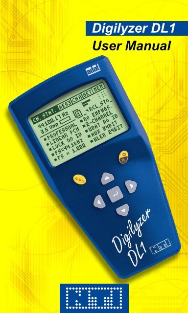
<strong>Digilyzer</strong> <strong>DL1</strong><br />
<strong>User</strong> <strong>Manual</strong>
NTi Audio Contact<br />
Headquarter: NTi Audio AG<br />
Im alten Riet 102<br />
9494 Schaan<br />
Liechtenstein, Europe<br />
Tel +423 - 239 6060<br />
Fax +423 - 239 6089<br />
E-mail info@nti-audio.com<br />
Home www.nti-audio.com<br />
NTi Audio is an ISO 9001:2008<br />
certified company.<br />
© NTi Audio AG<br />
All rights reserved.<br />
Subject to change without notice.<br />
Release 2.20 / May 2011 / Software D2.20<br />
<strong>Digilyzer</strong>, Minirator, Minilyzer, MiniSPL,<br />
MiniLINK and Minstruments are registered<br />
trademarks of NTi Audio.<br />
2<br />
Made in<br />
Switzerland
INdex:<br />
1. In t r o d u c t Io n 4<br />
CE Declaration of Conformity 4<br />
Registration 5<br />
International Warranty and Repair 6<br />
Warnings 7<br />
Test & Calibration Certificate 7<br />
Scope of Delivery 7<br />
2. ov e r v I e w 8<br />
Functions 9<br />
Monitoring 10<br />
Connectors 13<br />
Battery Replacement 14<br />
3. FIr s t st e p s 15<br />
4. Ba s Ic op e r a t Io n 18<br />
5. Me a s u r e M e n t Fu n c t Io n s 27<br />
Channel Status 27<br />
Bit Statistic 33<br />
Logger 35<br />
VU+PPM 39<br />
Level Measurement 41<br />
Level Peak 42<br />
Level RMS 43<br />
Level Sweep 45<br />
THD+N 47<br />
Scope 49<br />
6. tr o u B l e s h o o t In g 50<br />
7. ac c e s s o r I e s 51<br />
MiniLINK 51<br />
Mains Power Adapter 51<br />
Minstruments System Case 52<br />
Pouch 52<br />
8. ap p e n d I x 53<br />
1C2f Format 53<br />
Logger Event Coding 55<br />
Professional Format Coding 58<br />
Consumer Format Coding 61<br />
9. te c h n Ic a l sp e c I F Ic a t Io n 63<br />
3
1. INTroduCTIoN<br />
Congratulations and thank you for buying NTi Audio’s <strong>Digilyzer</strong><br />
<strong>DL1</strong>, a product specially suited for professional audio applications.<br />
The <strong>Digilyzer</strong> offers advanced analysis functions, expected only in<br />
much larger and more expensive systems. We are convinced you<br />
will enjoy using it!<br />
NTi Audio products are manufactured in compliance with the highest<br />
quality standards and marked with the CE sign.<br />
Ce declaration of Conformity<br />
We, the manufacturer<br />
NTi Audio AG<br />
Im alten Riet 102<br />
9494 Schaan<br />
Liechtenstein, Europe<br />
hereby declare that the product <strong>Digilyzer</strong> <strong>DL1</strong>, released in 2001,<br />
conforms to the following standards or other normative documents.<br />
EMC-Directives: 89/336, 92/31, 93/68<br />
Harmonized Standards: EN 61326-1<br />
This declaration becomes void in case of any changes on the product<br />
without written authorization by NTi Audio.<br />
Date: 01.11.2001<br />
Signature:<br />
Introduction<br />
Position of signatory: Technical Director<br />
4
egistration<br />
Introduction<br />
Register as a customer with NTi Audio and benefit from the following<br />
possibilities:<br />
• Keep your products up-to-date<br />
Access free firmware and software updates.<br />
• Activate options<br />
Enable additional functions for your products.<br />
• Access premium content<br />
Access downloads, information and specific support for your<br />
products.<br />
• Receive application and product news<br />
Sign in for the NTi Audio Newsletter.<br />
• Get fast worldwide support<br />
Register your products for fast support.<br />
• Confirm your ownership<br />
Allows us to contact you with important product notifications<br />
and provides a product record in case of loss or theft.<br />
How to register<br />
• Open the web page “http://my.nti-audio.com”.<br />
• You are prompted to login or create the My NTi Audio<br />
Account.<br />
• The web page “My NTi Audio Products” opens.<br />
• Select the product type and enter the serial number.<br />
• Confirm with “Register”.<br />
• Now the product is listed in the table “My NTi Audio<br />
Products“.<br />
5
International Warranty and repair<br />
International Warranty<br />
NTi Audio guarantees the <strong>Digilyzer</strong> <strong>DL1</strong> and its components against<br />
defects in material or workmanship for a period of one year from<br />
the date of original purchase, and agrees to repair or to replace at<br />
its discretion any defective unit at no cost for either parts or labor<br />
during this period.<br />
restrictions<br />
This warranty does not cover damages caused through accidents,<br />
misuse, lack of care, the attachment or installation of any components<br />
that were not provided with the product, loss of parts, connecting the<br />
instrument to a power supply, input signal voltage or connector type<br />
other than specified, or wrongly polarized batteries. In particular,<br />
no responsibility is granted for special, incidental or consequential<br />
damages.<br />
This warranty becomes void if servicing or repairs of the product are<br />
performed by any party other than an authorized NTi Audio service<br />
center or if the instrument has been opened in a manner other than<br />
specified in this manual.<br />
No other warranty, written or verbal, is authorized by NTi Audio.<br />
Except as otherwise stated in this warranty, NTi Audio makes no<br />
representation or warranty of any kind, expressed or implied in law<br />
or in fact, including, without limitation, merchandising or fitting for any<br />
particular purpose and assumes no liability, either in tort, strict liability,<br />
contract or warranty for products.<br />
repair of your digilyzer dL1<br />
Introduction<br />
In case of malfunction, take - or ship prepaid - your NTi Audio <strong>Digilyzer</strong><br />
packed in the original box, to the authorized NTi Audio representative<br />
in your country. For contact details see the NTi Audio web page.<br />
Be sure to include a copy of your sales invoice as prove of purchase<br />
date. Transit damages are not covered by this warranty.<br />
6
Warnings<br />
In order to avoid any problems during the operation of the instrument,<br />
follow the rules listed below:<br />
• Use the instrument for the intended purpose only.<br />
• Never connect the instrument to a high voltage output such<br />
as a power amplifier, mains power, etc.<br />
• Do not disassemble the instrument.<br />
• Never use the instrument in a damp environment.<br />
• Remove the batteries as soon as they are flat or if the<br />
instrument is not intended to be used for a longer period<br />
of time.<br />
Test & Calibration Certificate<br />
This is to certify the <strong>Digilyzer</strong> <strong>DL1</strong> is fully tested to the manufacturer’s<br />
specifications.<br />
NTi Audio recommends to calibrate this test instrument one (1) year<br />
after purchase. Thereafter the calibration- and adjustment interval is<br />
subsequently one (1) year.<br />
Scope of Delivery<br />
Introduction<br />
The following items are included with the packing:<br />
• <strong>Digilyzer</strong> <strong>DL1</strong><br />
• Rubber Cushion<br />
• Chinch-BNC Adapter<br />
• <strong>User</strong> <strong>Manual</strong><br />
7
2. overvIeW<br />
The <strong>Digilyzer</strong> is a sophisticated tool used to analyze digital audio<br />
signals. It is designed for easy and quick maintenance and debugging<br />
of digital audio equipment and installations. Therefore, the <strong>Digilyzer</strong><br />
observes the signals from many points of view simultaneously. An<br />
accurate overview of the actual signal condition is displayed on a large<br />
LCD and hidden errors are visualized (e.g. consistency check).<br />
Carrier<br />
information<br />
Quick status<br />
information<br />
Overview<br />
Menu bar<br />
Fig 2-01, Overview display<br />
8<br />
PPM meter<br />
By using the <strong>Digilyzer</strong> understanding and handling digital signals is<br />
simple. However, some basic knowledge about digital audio signals<br />
is essential. Please refer to our homepage for some easy literature<br />
about digital audio basics.<br />
Interface types<br />
The <strong>Digilyzer</strong> supports all common used interface types such as AES3,<br />
S/PDIF, TOS-LINK and ADAT. This range could be further extended<br />
by using external adapters or cheap equipment e.g. a TDIF to ADAT<br />
converter.
Functions<br />
Overview<br />
The <strong>Digilyzer</strong> features many useful measurement functions which are<br />
accessible through a menu bar.<br />
Fig 2-02, Measurement functions<br />
easy operation<br />
The <strong>Digilyzer</strong> has an easy to use menu driven user interface. Changing<br />
of the settings takes place at the displayed values – there is no<br />
complex setup screen. The base element for operational functions<br />
is the cursor (inverted area) which can be navigated through the<br />
various screens by using the cursor keys. All selectable settings may<br />
be adjusted individually by pressing the enter key and selecting the<br />
requested value with the cursor keys. Confirm the setting by pressing<br />
the enter key again.<br />
Fig 2-03, <strong>DL1</strong> menu<br />
9
Monitoring<br />
Overview<br />
Fig 2-04, Changing settings<br />
10<br />
Unit selected<br />
with cursor to<br />
change setting<br />
When it comes to digital audio, one of the major problems is, that<br />
humans do not have digital ears and thus can not listen to the<br />
incoming embedded audio signal. The <strong>Digilyzer</strong> offers a wide range<br />
of functionality to make digital audio audible.<br />
What you hear is what you measure<br />
• Functions with measurement of both channels (e.g. A+B), the<br />
output of the speaker is a mix of the two channel signals. Over<br />
the headphone output you may hear the signal in stereo (channel<br />
A on the left and channel B on the right side).<br />
Both channels A+B selected<br />
Fig 2-05, Channels A+B selected
• Some functions, e.g. SCOPE, are one channel functions only. You<br />
only hear the channel which is displayed on the screen.<br />
Digital versus analog<br />
Overview<br />
Channel B selected<br />
Fig 2-06, Channel B selected<br />
Installations with digital and analog audio lines often cause headache<br />
and struggles. In reality some analog line maybe connected and the<br />
<strong>Digilyzer</strong> can not lock to the (non digital) signal. Therefore, the <strong>Digilyzer</strong><br />
has the ability of analog monitoring. The <strong>Digilyzer</strong> may not lock to the<br />
input signal digitally, but it routes the signal directly to the speaker<br />
and headphone output, so you may hear the analog input signal<br />
acoustically. For visual clarification ANALOG MONITORING ON is<br />
flashing on the display.<br />
Fig 2-07, Analog monitoring<br />
11<br />
Flashing
Debugging or listening?<br />
The built-in speaker on the rear side gives the acoustical response of<br />
the measured signal – everywhere and any time – without the need<br />
of a headphone. For the users convenience a good headphone may<br />
be connected for listening in superior quality (up to 24 bit / 96 kHz).<br />
The headphone output may be used as D/A converter, e.g. some<br />
recording with a minidisc-player is requested but no analog output<br />
is available.<br />
oops – no signal!<br />
Often no signal is found during troubleshooting at digital audio lines.<br />
Can this be? The <strong>Digilyzer</strong> offers a digital realized “AGC” (automatic<br />
gain control) to “zoom up” the digital signal. So even a change of the<br />
LSB (least significant bit) is fully audible. The tremendous dynamic<br />
range of 140 dB allows to listen to the smallest disturbances. For<br />
example someone just has closed the fader or muted the signal, so<br />
just activate the AGC and listen; even dither noise will be audible.<br />
Hotkey-symbol<br />
All the above monitoring functionalities can be controlled by using<br />
hotkeys, displayed in the FAST ACCESS SETUP menu.<br />
dual domain measurements<br />
Overview<br />
Fig 2-08, Automatic gain control<br />
Level RMS and distortion (THD+N) measurements are fundamental to<br />
check A/D converters. The complete test system even checks mixed<br />
mode applications such as A/D converters or digital mixers is available<br />
in combination with the analog signal generator Minirator MR1.<br />
12<br />
Description<br />
hotkey AGC<br />
ON/OFF
Connectors<br />
The <strong>Digilyzer</strong> includes the following connectors:<br />
AES3, 110 Ohm<br />
terminated<br />
Overview<br />
S/PDIF, 75 Ohm<br />
terminated<br />
Fig 2-09, Inputs and outputs of <strong>DL1</strong><br />
NOTES • For AES3, 75 Ohm, signals (BNC connector) use the<br />
attached Chinch-BNC adapter.<br />
• Insert a jack into the headphone output to switch<br />
of the analog monitoring with the internal speaker<br />
(e.g. during a live act).<br />
Rubber Cushions<br />
The original packaging of the <strong>Digilyzer</strong> includes a pair of rubber<br />
cushions. These may be adhered on the rear side of the device, so the<br />
output signal is made audible in good quality also whilst the <strong>Digilyzer</strong><br />
lays, e.g. on a table, with the speaker on the bottom side.<br />
Chinch-BNC Adapter<br />
The Chinch-BNC Adapter enables the measurement of the AES3id,<br />
75 Ohm standard with the <strong>Digilyzer</strong>. AES3id is especially required<br />
for the transmission of digital signals over longer cables with a cable<br />
length >100 m.<br />
13<br />
Headphone<br />
output<br />
TOS-Link /<br />
ADAT
Battery replacement<br />
Insert three pieces of 1.5 V alkaline batteries, type AA, LR6, AM3 into<br />
the <strong>Digilyzer</strong> battery compartment, as shown below.<br />
1. Press 1. Press<br />
2. Pull<br />
Overview<br />
Rubber<br />
cushion<br />
Speaker<br />
Fig 2-10, Open battery compartment Fig 2-11, Inserted batteries<br />
NOTE • The use of rechargeable NiCd- or NiMH-batteries<br />
causes shorter battery lifetime than specified.<br />
• Do not insert batteries of different types.<br />
• Note the correct polarities of the inserted batteries.<br />
• Remove the batteries as soon as they are flat.<br />
14
3. FIrsT sTeps<br />
This chapter is a quick guide explaining how to make the first<br />
measurements with the <strong>Digilyzer</strong>. The example assumes an S/PDIF<br />
signal as input (e.g. a CD player with S/PDIF output playing a music<br />
CD).<br />
1. Insert batteries<br />
2. Connect the S/PDIF signal to<br />
the RCA input.<br />
3. Reset the <strong>Digilyzer</strong> to default<br />
state by holding down the<br />
ESC key and simultaneously<br />
pressing the ON button for<br />
about two seconds.<br />
4. Select S/PDIF as input<br />
format<br />
- Move the cursor (inverted box)<br />
one step right to the format<br />
menu by using the cursor<br />
keys.<br />
- Press the enter key to open<br />
the format menu.<br />
- Select S/PD and press the<br />
enter key.<br />
-> The channel status information<br />
is displayed and music is<br />
audible trough the built-in<br />
speaker.<br />
First Steps<br />
15<br />
3<br />
2<br />
Fig 3-01, <strong>Digilyzer</strong><br />
Fig 3-02, Format selection<br />
4
5. Decrease the volume<br />
Press and hold the ESC- and<br />
left cursor key simultaneously.<br />
This causes the FAST<br />
ACCESS SETUP screen to<br />
be displayed and the volume<br />
to decrease.<br />
6. Measure the accuracy of the<br />
sampling rate<br />
The accuracy is measured<br />
in ppm, so the unit of the<br />
sampling frequency has to be<br />
changed as follows:<br />
- Move the cursor to the unit<br />
“Hz”.<br />
- Press the enter key to select.<br />
- Press any cursor key to<br />
change from “Hz” to “ppm”.<br />
-> The measured accuracy is<br />
immediately displayed.<br />
- Press the enter key to confirm<br />
the new setting.<br />
7. A c t i v a t e t h e V U + P P M<br />
function<br />
- Press the ESC key twice<br />
(cursor moves to the left<br />
top!).<br />
- Press the enter key to open<br />
the measurement menu.<br />
- Move the cursor down to<br />
VU+PPM.<br />
- Press the enter key to confirm<br />
the new setting.<br />
First Steps<br />
16<br />
Decrease/increase<br />
volume hot-keys<br />
5. Volume<br />
indication<br />
Fig 3-03, Volume setting<br />
6<br />
Fig 3-04, PPM setting<br />
Fig 3-05, VU+PPM mode<br />
7
8. Change auto power off time<br />
- Move the cursor to SET on the<br />
menu line and press the enter<br />
key.<br />
- Select AUTO POWER OFF<br />
with the cursor keys and press<br />
the enter key.<br />
- Set the time to 60 MIN with the<br />
cursor keys.<br />
- Confirm the setting with the<br />
enter key.<br />
- Press ESC to leave the<br />
SETUP screen.<br />
9. Backlight / power off<br />
- Press the On/Off key shortly<br />
to energize the backlight.<br />
- The backlight remains active<br />
according to the setting in the<br />
SETUP menu.<br />
- Press the On/Off key for<br />
two seconds to switch the<br />
instrument off.<br />
First Steps<br />
Congratulations, the first steps have been done with the <strong>Digilyzer</strong> to<br />
support the basic knowledge of the menu and device handling.<br />
NOTE • Pressing the enter key changes a value directly or<br />
enters the selection mode (blinking cursor). The<br />
available settings may be selected with the cursor<br />
keys.<br />
• In the selection mode you may press<br />
- ENTER to confirm the setting<br />
- ESC key to undo the setting.<br />
17<br />
Fig 3-06, Auto power off setting<br />
8
4. BAsIC operATIoN<br />
The operation of the <strong>Digilyzer</strong> is almost self-explanatory, despite the<br />
wide range of available measurement functions.<br />
Speaker at<br />
the rear-side<br />
Escape<br />
button<br />
Enter /<br />
Cursor keys<br />
Basic Operation<br />
Fig 4-01, Control elements<br />
The LCD is divided into the menu bar on top and the results displayed<br />
below, showing various information about the current status.<br />
To quickly get the required information press the enter / cursor keys<br />
and the escape button to allow straightforward navigation through the<br />
available features. The cursor position is represented by an inverted<br />
display (white on black) of the field holding the cursor.<br />
When the <strong>Digilyzer</strong> is on, it will utilize the same measurement function<br />
settings as switched off the last time.<br />
18<br />
Power On/Off-<br />
Backlight
Menu Bar<br />
The menu bar allows the user to select the<br />
Measurement<br />
function<br />
Basic Operation<br />
Input<br />
source<br />
Fig 4-03, Measurement function menu<br />
Fig 4-04, Input source menu<br />
19<br />
Input<br />
format<br />
Fig 4-02, Menu bar<br />
Setup<br />
screen<br />
Battery status,<br />
(indication only)
Basic Operation<br />
Any of the following formats may be selected<br />
• AES3<br />
• S/PD - abbreviation for S/PDIF<br />
• TOSL - abbreviation for TOS-LINK<br />
• ADAT - ADAT format via the TOS-Link input<br />
• 1C2f - abbreviation of the single channel double sampling<br />
frequency mode, see details to this mode in the appendix.<br />
Fig 4-05, Format menu<br />
Selection of Input Channel<br />
Corresponding to the selected input source the available input<br />
channels may be selected. The individual measurement result of<br />
each channel is displayed. For a better understanding of the input<br />
channels:<br />
• Channel A the left side of a headphone<br />
• Channel B the right side of a headphone.<br />
Indicator for operation / Low Battery<br />
A moving sine symbol indicates that the<br />
unit is running properly.<br />
Alternatively, this field shows a low<br />
battery indicator.<br />
20<br />
Fig 4-06, Low battery indicator
setup screen<br />
Basic Operation<br />
The setup screen allows to customize basic settings of the<br />
<strong>Digilyzer</strong>.<br />
Fig 4-07, Setup screen<br />
AuTo poWer oFF defines the time of the automatically switch off<br />
after the last key-press.<br />
AuTo LIGHT oFF defines how long the backlight stays on after<br />
being activated.<br />
ppM over THresH defines the number of full scale values, causing<br />
a clipping indication at the ppm meter.<br />
MuLTIpLe seTup allows four users to store their individual settings.<br />
To enable the multiple setup mode, set the corresponding entry to<br />
ENABLE. The next time the <strong>Digilyzer</strong> is switched on, the user will<br />
have to select the individual setup-ID (1, 2, 3 or 4) in the startup<br />
screen. All parameter settings in all measurement modes are now<br />
stored under this ID at the switch off and are recalled if this ID is<br />
selected at the next start up.<br />
Fig 4-08, Multiple user startup screen<br />
21
Fast Access setup<br />
Basic Operation<br />
Some key combinations allow fast access to the most frequently used<br />
settings. Pressing a hot key combination shows the FAST ACCESS<br />
SETUP screen and changes the value. If you don’t remember the key<br />
combinations just press ESC for two seconds and the FAST ACCESS<br />
SETUP is displayed.<br />
ESC + up,<br />
higher LCD<br />
contrast<br />
ESC + down,<br />
lower LCD<br />
contrast<br />
ESC + enter,<br />
AGC on/off<br />
ESC + left,<br />
volume down<br />
Fig 4-09, Fast access setup screen<br />
The symbolized keypad on the left part of the screen indicates the<br />
hot keys function of the individual buttons. The actual adjustment is<br />
shown on the right side of the display.<br />
VOLUME, setting of speaker volume. The volume control and the<br />
mute/unmute settings do not influence the analog monitoring.<br />
Analog audio signals are made audible with the speaker, but no<br />
measurement result is displayed. In this way analog audio signals<br />
are immediately indicated to the user. To analyze an analog signal<br />
the Minilyzer ML1 is recommended to be used.<br />
AUT. GAIN CONTROL (AGC), all incoming signals are leveled to<br />
the same loudness, even if the signals are -60 dBF. The AGC<br />
amplifies a signal up to 140 dB, so even dithering noise on a silent<br />
line is audible!<br />
CONTRAST, setting of the display contrast. For the detailed readout<br />
of fast changing display indications, e.g. SCOPE or VU+PPM, an<br />
increased LCD contrast is recommended to be set.<br />
22<br />
ESC + on/off,<br />
mute/unmute<br />
speaker<br />
ESC + right,<br />
volume up<br />
Speaker<br />
muted
display Basics<br />
Debugging and analyzing digital audio signals need a few explanation<br />
to be best visualized at the same time. For example, a recorder does<br />
not recognize the incoming signal, so it is important to find out:<br />
• Is there a digital or an analog signal on the line?<br />
• Is there any audible information on the digital line?<br />
• What is the format of the data (consumer / professional)?<br />
• Does the signalized channel status correspond to the data?<br />
• What’s the level and the frequency of the carrier?<br />
• … and much more<br />
In many measurement functions the <strong>Digilyzer</strong> answers all these<br />
questions at the same time. For easy readout several screen elements<br />
are available on most functions.<br />
Carrier<br />
information<br />
Quick status<br />
information<br />
Basic Operation<br />
Fig 4-10, Screen elements<br />
23<br />
PPM meter<br />
Emphasis
Carrier Information<br />
Carrier<br />
level<br />
Carrier frequency displays the measured frequency in<br />
• Hz<br />
• ppm, deviation to the next standard frequency<br />
Carrier level indicates the measured carrier level in Vpp. Levels higher<br />
than 5.0 Vpp are indicated as >5 Vpp.<br />
Application hint:<br />
Basic Operation<br />
Fig 4-11, Carrier information<br />
Error indicator box: The <strong>Digilyzer</strong> checks the digital signal, its<br />
protocol and recognizes a number of errors. These errors can cause<br />
many audible effects, which should ideally never occur. An error is<br />
immediately indicated by the <strong>Digilyzer</strong> by filling the error indicator<br />
box black. Afterwards the box empties within ten seconds.<br />
24<br />
Carrier frequency<br />
Error indicator box<br />
The carrier level is a robust first approximation of signal quality.<br />
With decent short interconnection cables the carrier level<br />
• of an AES3 signal is in the range of 2 to 7 Vpp<br />
• of a S/PDIF signal is in the range of 200 to 700 mVpp<br />
With impedance problems involved or with long cables the<br />
AES3 signal level may drop to levels below these values, so<br />
the reliability gets worse.
Following errors are analyzed/visualized in the error indicator box:<br />
• Lock / unlock<br />
• Validity bit<br />
• Confidence bit (the received data eye pattern opening is less than<br />
half of a bit period, indicating a poor link not meeting specs)<br />
• Bi-phase mark coding error<br />
• Parity error<br />
• Carrier level below specification (for AES3 and S/PDIF input)<br />
NOTE The lock/unlock state is the only available error in the<br />
AdAT format.<br />
ppM Meter<br />
Many measurement functions include a PPM meter, displaying the<br />
measured level peak in bargraph form. The scaling details are:<br />
Channel A<br />
Channel B<br />
-60 dBF<br />
Basic Operation<br />
-10 dBF -3 dBF 0 dBF<br />
Fig 4-12, Bargraph markings<br />
NOTE • For signal levels lower than -60 dBF the vertical line<br />
marked above with -60 dBF remains displayed and<br />
changes for muted signals to three dots.<br />
• The number of full scale values causing clipping<br />
indication can be set in the SETUP menu (PPM<br />
OVER THRESH). By default it is set to three<br />
samples.<br />
25<br />
Signal<br />
clipping<br />
indication
Emphasis<br />
The <strong>Digilyzer</strong> does not de-emphase any pre-emphased signals. In<br />
case the incoming signal is marked as pre-emphased in the channel<br />
status, the <strong>Digilyzer</strong> indicates this with PRE-EMPH displayed below<br />
the PPM meter (at all measurement functions with display space<br />
available).<br />
Indication<br />
Quick Status Information<br />
In the measurement functions BIT STAT., VU+PPM, LEVEL and<br />
THD+N the essentials of the channel status information are displayed<br />
continuously:<br />
Format Sampling<br />
frequency<br />
Basic Operation<br />
Fig 4-13, Emphasis<br />
The consistency check is constantly running as a background task.<br />
It highlights any parameter showing inconsistency within the physical<br />
parameter. For example, as shown in the above figure, the resolution<br />
claims to be a 24 bit, but in reality it is lower.<br />
26<br />
Resolution,<br />
word length<br />
Fig 4-14, Quick status information<br />
Channel<br />
information
5. MeAsureMeNT FuNCTIoNs<br />
Channel Status<br />
Measurement Functions<br />
Digital audio signals (formats AES3 and S/PDIF) have additional<br />
information called channel status, encoded in the signal bit stream.<br />
The <strong>Digilyzer</strong> directly translates the contents of the status bits and<br />
displays the results on the channel status screen, thus enabling the<br />
user to directly read the meanings.<br />
The proper interpretation of the status bits is carried out automatically<br />
by the <strong>Digilyzer</strong>. The first bit of the channel status indicates whether<br />
the status bits are configured in professional or consumer format.<br />
The professional format has various additional information encoded<br />
in the channel status, whereby in the consumer format, the copy<br />
protection is the major concern. ADAT signals do not carry any<br />
status information, so the display will indicate CHANNEL STATUS<br />
NOT AVAILABLE ON ADAT.<br />
To display the complete status information three different pages are<br />
available:<br />
• page 1, main status information<br />
• page 2, additional status information<br />
• page 3, status information in hex code<br />
The page number is displayed at the top center of the measurement<br />
screen. Select the page number with the cursor and press enter to<br />
select the next page.<br />
27
professional Format<br />
Format<br />
Data coding<br />
Fs locked<br />
Sampling frequ.<br />
Fs scaling<br />
Level alignment<br />
Reference signal<br />
Time of day<br />
Sample code<br />
Data origin/<br />
destination<br />
Measurement Functions<br />
Page number<br />
Fig 5-01 Channel status professional, page 1<br />
Page number<br />
Fig 5-02 Channel status professional, page 2<br />
Further details to the individual status indications are listed in the<br />
appendix.<br />
28<br />
Status<br />
memory<br />
Status<br />
memory<br />
Signal emphasis<br />
Channel mode<br />
<strong>User</strong> bit format<br />
Auxiliary bit use<br />
Word length<br />
Data reliability<br />
Cyclic<br />
redundancy<br />
check
Row number<br />
Measurement Functions<br />
Page number<br />
Fig 5-03, Channel status professional, page 3<br />
On the third page the complete status information is displayed as hex<br />
code. The content of each status byte is shown as two digits in hex<br />
code. The status information contains 24 bytes. These are displayed<br />
within three rows and eight columns. The individual row- and column<br />
numbers shall be added together to read the information containing<br />
in the corresponding byte number.<br />
e.g. row number + column number = byte number<br />
0 + 4 = 4<br />
8 + 6 = 14<br />
10 (hex) + 2 = 18<br />
Application hint:<br />
29<br />
Column<br />
number<br />
There are many undefined and reserved bit combinations in the<br />
channels status. The HEX view offers the possibility to further<br />
examine the reserved states - if necessary.
Consumer Format<br />
Format<br />
Data coding<br />
Sampling frequ.<br />
Clock accuracy<br />
Category code<br />
Copy protection<br />
Original fs<br />
Measurement Functions<br />
Page number<br />
Fig 5-04, Channel status consumer, page 1<br />
Page number<br />
On page two are the fairly complex category tables, providing simple<br />
device statements, such as e.g. LASER OPTICAL PROD or MINI<br />
DISC SYSTEM, interpreted into words and letters for easy read out.<br />
The original sampling frequency field is used to indicate the fs of the<br />
signal prior sampling frequency conversion in a consumer playback<br />
format.<br />
Page three displays the complete status information as hex code.<br />
30<br />
Status<br />
memory<br />
Fig 5-05, Channel status consumer, page 2<br />
Channel mode<br />
signal emphasis<br />
Source number<br />
Channel number<br />
Word length
Consistency Check<br />
The consistency check is constantly running as a background task. It<br />
compares the carrier information with the status information. E.g. the<br />
sampling frequency claims to be 44.1 kHz but in reality is 48.0 kHz.<br />
Such errors are immediately displayed via a flashing square around<br />
the individual status information.<br />
Measured<br />
sampling<br />
frequency<br />
Wrong sample<br />
frequ. status<br />
information<br />
Measurement Functions<br />
Fig 5-06, Channel status consistency check<br />
The consistency check is carried out with the following parameters:<br />
• Sample frequency<br />
• Word length<br />
• Clock accuracy<br />
• 1C2f usage<br />
Application hints:<br />
• Wrong signalization of the sample frequency of digital audio<br />
devices may cause real trouble.<br />
• Some units expected to be e.g. 24 bit devices, signalize 24<br />
bit in the channel status but only send 22 relevant bits. The<br />
consistency check helps to see this problems quick and<br />
easy.<br />
Channel Status Details<br />
Detailed information about the interpretation of each individual bit and<br />
bytes may be found in the normative documents IEC 60958-3 and<br />
AES3. A summary is given in the appendix.<br />
31
Measurement Functions<br />
Channel Status Comparison<br />
Both channels of an AES3 or S/PDIF signal have their individual<br />
channel status information. In 99% of all applications the content is<br />
identical. In case of any difference the small square indicators in front<br />
of each label would turn into triangles and constantly toggle.<br />
Fig 5-07, Channel status comparison<br />
Channel Status Memory<br />
The current channel status information may be stored and recalled.<br />
Recall<br />
memory<br />
Select STO with the cursor and press enter to store the actual status<br />
information. If any bit in the status is now altered compared to the<br />
currently stored status, the square flag on the left side of RCL will turn<br />
into the toggling triangle, indicating discrepancies. By selecting and<br />
holding RCL the memorized status information may be recalled for a<br />
quick check of the status difference. The status memory remains also<br />
valid after switching off the device.<br />
32<br />
Channel A<br />
selected<br />
Fig 5-08, Channel status memory field<br />
Different status<br />
information of<br />
channel A and B<br />
Store actual<br />
status
Bit statistic<br />
The bit statistic function visualizes the state of all bits in the digital<br />
audio signal.<br />
Actual word<br />
length<br />
Auxiliary bits<br />
Measurement Functions<br />
VUCP data<br />
Fig 5-10, Bit statistic panel<br />
The display allows you to see quickly which bits of the audio data are<br />
permanently low (0), high (1) or changing (indicated via the up/down<br />
arrow symbol).<br />
Actual word length: The actually measured resolution is<br />
displayed.<br />
vuCp data: The following bit information is displayed:<br />
• V, validity bit indicating whether the digital audio bits may<br />
be converted to an analog audio signal; if the validity bit is<br />
permanently 0, the incoming data is valid.<br />
• U, user bit containing any user bit information.<br />
• C, status bit containing the channel status information, this bit<br />
is normally changing.<br />
• P, parity bit, plausibility check of actual subframe, this bit is<br />
normally changing.<br />
Auxiliary bits: These bits may be used for<br />
• Audio data<br />
• 2 nd channel, e.g. talk back<br />
33<br />
Audio data,<br />
channel A,<br />
channel B
Audio data: The two lines represent the 20 bit audio word for both<br />
channels.<br />
• LSB on the left side, least significant bit<br />
• MSB on the right side, most significant bit<br />
The right bits always have to be active. In case some of the left bits<br />
are constantly 0, the resolution of the audio signal is obviously less<br />
than the maximum of 24 bits (including the aux. bits). The number<br />
of arrows from right to left may be counted to find the actual word<br />
length or binary resolution.<br />
Application hints:<br />
Measurement Functions<br />
• Any digital input signal causes that some of the MSB’s are<br />
active. The <strong>Digilyzer</strong> counts the number of active bits and<br />
displays the result as actual word length.<br />
• Sometimes bits of the input signal are stucked on “0“ or “1“.<br />
In such a case a device in the signal chain is defective, e.g.<br />
a receiver or a transmitter.<br />
34
Logger<br />
The event logger records any irregularity of the digital signals. Besides<br />
the common expectations events such as change of sampling<br />
frequency, word length, consistency check results and many more<br />
are covered.<br />
What is an event?<br />
Events are changes or irregularities of the input signal. They are<br />
acquired for the two channels separately (wherever reasonable) and<br />
are split into the following categories:<br />
• Carrier based events<br />
• Frame based events<br />
• Audio signal based events<br />
• Channel status based events<br />
• Consistency check based events<br />
Basics of logging<br />
Measurement Functions<br />
Whilst a log is running, the <strong>Digilyzer</strong> acquires all events (details are<br />
listed in the Appendix). The <strong>Digilyzer</strong> bundles all events which are<br />
occurred within the recording interval. It generates a new “record”<br />
when a recording interval has finished. The recording interval can be<br />
adjusted at the start of a new log.<br />
Basic setting of logger data<br />
Fig 5-20, Recording setup window<br />
35<br />
Record<br />
field<br />
Recording<br />
interval<br />
Calculated<br />
maximum<br />
recording<br />
length
• Select the REC field, press enter and the RECORD window is<br />
displayed.<br />
• Select the recording interval of the recording. The max.<br />
recording length is defined by this resolution. The <strong>Digilyzer</strong> has<br />
the capability to store data of 500 recording intervals. A higher<br />
recording interval is causing a shorter maximum recording<br />
length.<br />
• Select and confirm GO! to start the logger function. The<br />
recording setup window disappears and the REC field is<br />
flashing.<br />
• The logging may be stopped by pressing the enter key at the<br />
REC field.<br />
Mask frame<br />
Sum of event<br />
occurances<br />
Event list<br />
Measurement Functions<br />
Sum of all<br />
events in<br />
event list<br />
Fig 5-21, Overview records<br />
Display interval: The events occurred during the user defined<br />
display interval are summarized and shown on the <strong>Digilyzer</strong>. The<br />
bundling of logger data helps to make the events more clear and<br />
easy to overview.<br />
After the logging is completed the display interval may be<br />
changed.<br />
• Zoom out the intervals, e.g. the error log has a recording interval<br />
of ten seconds and you want to know how many events have<br />
been found in the last hour, just zoom out to a display interval<br />
of one hour.<br />
• Zoom in to get a more detailed information about the time of<br />
individual events occurred.<br />
• Set to ALL (maximum zoom out) to get an overview of all<br />
records.<br />
36<br />
Display interval<br />
Event name
Displaying events<br />
The display of the event logger is split into three areas:<br />
Basic<br />
setting<br />
Event list<br />
Logger<br />
info line<br />
Measurement Functions<br />
Fig 5-22, Detailed info of records<br />
Event list: After the cursor is navigated to the event list, it can<br />
be scrolled with the up/down key. In this mode the data can be<br />
zoomed by using the left and right arrow keys. Press ESC to quit<br />
the event list.<br />
Logger info line: While the cursor is in the event list, the individual<br />
detailed information to the selected event is displayed. Many errors<br />
may occur on channel A or B separately (e.g. AU OVERLOAD)<br />
and be indicated.<br />
37
Masking events<br />
Measurement Functions<br />
For a better overview some events can be hidden from the logging<br />
display (e.g. the audio signal clips very often or the channel status<br />
changes permanently because of time code). Therefore, the <strong>Digilyzer</strong><br />
offers you the possibility to select which events you want to see or<br />
hide. Select the field MASK to enter to the LOGGER DISPLAY MASK<br />
screen.<br />
Event<br />
categories<br />
All masking<br />
on/off<br />
The first column displays all event categories. The complete event<br />
category or single events of each category can be masked. The filled<br />
square indicates that the event is displayed at the event list.<br />
NOTE Masking does not effect the recording.<br />
All events are logged at anytime.<br />
Overview of used event coding<br />
See Appendix.<br />
Application hint:<br />
Fig 5-23, Logger display mask<br />
To read out one specific event only<br />
38<br />
Event visible at<br />
event list<br />
Event masked<br />
(not visible at<br />
event list)<br />
- select in the LOGGER DISPLAY MASK the ALL ON/OFF field<br />
and press enter -> all squares will be empty<br />
- select the specific event you are looking for, press enter and the<br />
specific square is filled up
vu+ppM<br />
The <strong>Digilyzer</strong> offers a combined VU and PPM meter for two channels<br />
(stereo). This combination enables a quick and accurate overview on<br />
the momentary peak level and RMS value (power of the signal, which<br />
tends to be an indication for the volume).<br />
Channel A<br />
Channel B<br />
Measurement Functions<br />
VU meter<br />
(thick bar)<br />
Fig 5-30, VU+PPM panel<br />
Numerical peak hold indicates the all-time max. input peak level<br />
of each channel since the VU+PPM mode has been entered. It<br />
may be reset by placing the cursor on this value and pressing<br />
the return key.<br />
Over indicator: Clipping indication; the number of full scale values<br />
causing this clipping indication may be adjusted in the SET menu<br />
(PPM OVER THRESH).<br />
vu+ppM Indication: <strong>Digilyzer</strong> features<br />
• VU, volume units indicated as the thick bar; displays the average<br />
volume level of the audio signal.<br />
• PPM, peak program meter indicated as the center bar; displays<br />
the peak level of the audio signal.<br />
39<br />
PPM meter<br />
(thin bar)<br />
Numerical<br />
peak hold<br />
Over<br />
indicator<br />
Peak hold<br />
for PPM
Application hint:<br />
Measurement Functions<br />
Broadcast levels are limited to a maximum output peak level. This<br />
is in order to not to overload the transmission lines and to avoid<br />
unpleasant and audible distortions. During tuning through the radio<br />
stations it is clearly noticeable, that some channels are much louder<br />
than others; purposely to increase awareness!<br />
This is accomplished by using compressors and other dynamic<br />
signal processing devices. The intention is to make the material as<br />
loud as possible without exceeding the maximum peak level. Simply<br />
feed the digital audio signal into the <strong>Digilyzer</strong> and it displays for both<br />
channels the peak- and VU-levels. The closer the VU level is to the<br />
PPM level, the higher is the compression of the audio material.<br />
40
Level Measurement<br />
The Level menu features three different measurement selections to<br />
choose from:<br />
• Level peak<br />
• Level RMS<br />
• Level sweep<br />
Level peak measurements indicate – thought digitally – the maximum<br />
number (value) of the input signal.<br />
Level RMS measures the power of the signal. The RMS functions of<br />
the <strong>Digilyzer</strong> such as Level RMS, sweep and THD+N are available<br />
as single channel functions only.<br />
Level sweep, based on RMS measurement.<br />
Application hint:<br />
Measurement Functions<br />
Fig 5-40, Level selection menu<br />
In digital audio the level peak measurement is basically mostly used,<br />
while in the analog area RMS values are important. Whenever you<br />
want to make measurements in the area of “frequency response”,<br />
RMS is usually the correct choice.<br />
41
Level Peak<br />
The Level peak function displays the actual peak value of the<br />
incoming digital audio signal. The digital peak level measurement<br />
provides information about the peak-to-peak signal level, compared to<br />
the full scale of the converter. The result is displayed simultaneously<br />
for both channels in numerical letters and in analog form, indicated<br />
in a bargraph.<br />
Result<br />
and unit<br />
Fig 5-41, Level peak screen<br />
result and unit: The peak level can be displayed in three different<br />
units<br />
• dBF (decibel full scale)<br />
• % (percent of full scale)<br />
• x1 (number, e.g. 0.1 of full scale)<br />
The peak level units refer to the maximum possible level of the<br />
digital signal (100% or 0 dBF).<br />
Application hint:<br />
Measurement Functions<br />
42<br />
Channel<br />
indication<br />
To measure the peak level during a period of time, use the VU+PPM<br />
function and monitor the numerical peak hold values.
Level RMS<br />
The analog Level RMS function measures the RMS level of the digital<br />
input signal. Since the <strong>Digilyzer</strong> has no information about the reference<br />
voltage, such as the<br />
• value to digitize the analog signal<br />
• value to convert the digital signal into the analog domain<br />
The RMS values are displayed as relative numbers compared to a<br />
sine wave signal with 0 dBF (peak value).<br />
Result<br />
and unit<br />
Filter<br />
Measurement Functions<br />
Audio frequency<br />
Fig 5-42, Level RMS<br />
result and unit: The RMS level of the individual selected channel<br />
can be displayed in three different units:<br />
• dBr (decibel relative)<br />
• % (percent of full scale)<br />
• x1 (number)<br />
In case the measured RMS value is smaller than -100 dBr, the<br />
<strong>Digilyzer</strong> displays “
Measurement Functions<br />
display mode: Giving a better readability the display mode<br />
determines the rapidity of following up the input signal changes.<br />
The available modes are:<br />
• SLOW 3 seconds averaging<br />
• NRM 1 seconds averaging<br />
• FAST no averaging<br />
If averaging is active, measurements are smoothed in an exponential<br />
way (exponential time constant) before being displayed.<br />
44
Level Sweep<br />
The <strong>Digilyzer</strong> supports a RMS based frequency sweep. This function<br />
can be applied to measure the frequency response of devices.<br />
During a frequency sweep, the <strong>Digilyzer</strong> records the Level RMS of<br />
every input signal, that has a stable frequency and level, provided that<br />
the frequency is higher than the one of the previous sample (otherwise<br />
the sample will be neglected).<br />
Arrow mode<br />
Zoom<br />
Y-Scale<br />
Measurement Functions<br />
Fig 5-43, Frequency sweep graph<br />
Within a graph every recorded sample is connected by a straight<br />
line approximately to the previous / next sample, thus building the<br />
displayed curve.<br />
In practice the following steps are required / available for the execution<br />
of a frequency sweep.<br />
• Arm the sweep recording process by moving the cursor to the<br />
REC field and pressing the enter key.<br />
• The <strong>DL1</strong> detects the start tone (315 Hz or 1 kHz) of an external<br />
sweep and the recording is automatically started. This status<br />
is indicated by the flashing REC field.<br />
Alternatively, the sweep recording may be started manually<br />
by pressing the enter key with the cursor on the ARM field.<br />
Consequently, the <strong>DL1</strong> records every incoming signal with a<br />
higher frequency than the previous sample.<br />
45<br />
Arrow readout
Measurement Functions<br />
• The sweep recording will be stopped when as soon as an input<br />
signal with a lower frequency occurs or manually by the enter<br />
key pressed again (cursor on the flashing REC field).<br />
• In order to analyze the sampled curve more detailed activate the<br />
arrow mode by placing the cursor to the corresponding symbol.<br />
Press the enter key and move the arrow to the sample(s) of<br />
interest by using the left / right keys.<br />
• To zoom in/out the Y-axis move the cursor to the zoom mode<br />
field, press enter and use the left / right keys.<br />
• To scroll through the Y-axis move the cursor to the zoom mode<br />
field, press enter and use the up / down keys.<br />
The last recorded sweep curve will be stored internally, even after<br />
leaving the sweep mode or switching off the <strong>Digilyzer</strong>. As soon as<br />
the frequency sweep mode is re-entered, the curve will re-appear on<br />
the graph until a new frequency sweep is started.<br />
NOTE The auto power off is disabled during a frequency<br />
sweep recording.<br />
Test signal:<br />
The sweep measurement can be carried out by using the sweep signal<br />
produced by the Minirator MR1, the "NTi Audio Wavefile Generator"<br />
software or other external sweeps with the following pre-conditions:<br />
• Signal type: Stepped sweep<br />
• Step time: min. 1 second / step<br />
• Frequency step: min. 1% increase<br />
• Max. number of steps: 160<br />
• Start frequency: 20 Hz<br />
46
THd+N<br />
The THD+N function (Total Harmonic Distortion+Noise) calculates<br />
the deviation of the input signal from an ideal sine wave. This<br />
measurement is most important to check and qualify analog/digital<br />
converters.<br />
Full scale<br />
indication<br />
Filter<br />
Measurement Functions<br />
Fundamental<br />
frequency<br />
Fig 5-50, THD + N screen<br />
The <strong>Digilyzer</strong> is able to calculate THD+N values down to –100dB<br />
(0.001%). For better THD+N values “< -100 dB“ (< 0.001%) are<br />
displayed.<br />
THd+N results of the selected channel may be displayed in dB or %.<br />
Full scale indication appears whenever one sample reaches full<br />
scale. This indication is independent of the clipping of the PPM<br />
meter.<br />
Filter: The audio signal decoded from the digital audio stream can<br />
be filtered with the following filters prior to the RMS or THD+N<br />
calculations:<br />
• HP400, highpass 400 has a good rejection in the area of main<br />
frequencies – so hum problems may easily be examined and<br />
localized. The HP400 is also used to measure quantization<br />
noise.<br />
• 22-22k, bandpass 22-22k is used to define the commonly used<br />
measurement bandwidth from 22Hz to 22kHz.<br />
47<br />
Level RMS<br />
THD+N<br />
result<br />
Display mode
Measurement Functions<br />
display mode: Giving a better readability the display mode<br />
determines the rapidity of following up the input signal changes.<br />
The available modes are:<br />
• SLOW 3 sec. averaging<br />
• NRM 1 sec. averaging<br />
• FAST no averaging<br />
If averaging is active measurements are smoothed in an exponential<br />
way (exponential time constant) before being displayed.<br />
Application hints:<br />
• Whenever one sample reaches full scale, slight clipping of the<br />
signal is possible so the THD+N value may degrade. Therefore,<br />
try to level the signal so the full scale indication does not<br />
appear.<br />
• An analog to digital (A/D) converter may show the following<br />
errors at the signal conversion:<br />
• The imperfect linearity of the converter adds (hopefully little)<br />
new harmonics to the signal.<br />
• Every analog part generates noise which is added to the<br />
signal during conversion.<br />
• An A/D converter has only a finite resolution (e.g. 16 bit), so<br />
the converter must round each sample value, which results<br />
in an error called quantization noise.<br />
A perfect test signal fed into an ideal A/D converter causes a<br />
THD+N of the digitized signal of theoretically<br />
-N * 6.02 dB - 1.76 dB (N ... bit resolution of the converter)<br />
E.g. a 16 bit converter has a theoretical THD+N of -98.08 dB.<br />
In practice good converters (even 24 bit) do not achieve better<br />
values than -110 dB. With such measurements the input signal<br />
is often the limiting point. To measure THD+N down to -100 dB<br />
a generated sine wave with a THD+N better than -100 dB is<br />
required. Such a sine wave is often generated only by expensive,<br />
special audio analyzing equipment.<br />
48
scope<br />
The scope shows the waveform of the input signal. It measures the<br />
• dominating fundamental frequency<br />
• momentary peak level<br />
and adjusts the X and Y-axis scaling automatically.<br />
Y-Axis<br />
scale<br />
Measurement Functions<br />
X-Axis scale<br />
Fig 5-60, Scope screen<br />
Y-Axis scale: Automatic scaling from 25%/div to 0.1ppm/div (allowing<br />
to see the LSB of a 24 bit signal).<br />
Actual level peak: Since it is sometimes difficult to get a feeling for<br />
values of e.g. 0.6 ppm, the actual peak level of the data shown on<br />
the screen is displayed in dBF.<br />
X-Axis scale: Automatic scaling from 1 to 500 samples per<br />
division.<br />
pause: The scope display may be paused by selecting this field with<br />
the cursor and pressing the enter key.<br />
Fundamental frequency: The input signals that fundamental or most<br />
dominant frequency are displayed.<br />
NOTE The scaling of the SCOPE display cannot be changed<br />
manually.<br />
49<br />
Fundamental<br />
frequency<br />
Pause<br />
Actual<br />
level peak
6. TrouBLesHooTING<br />
In case the <strong>Digilyzer</strong> is malfunctioning the software may be reset to<br />
factory set up as described below.<br />
System Break Down<br />
• Switch off the device.<br />
• Reset the <strong>Digilyzer</strong> to the default status by pressing the ESC<br />
button and switching on the <strong>Digilyzer</strong> simultaneously.<br />
• Release the ESC button.<br />
• The below screenshot will appear on the display stating on the<br />
bottom line LOADING DEFAULT SETUP.<br />
• Verify the correct operation.<br />
Serial number<br />
In case you find system breakdowns happening several times or your<br />
device is malfunctioning, please note serial number and software<br />
release number and contact the local NTi Audio representative in<br />
your country.<br />
For contact details see the NTi Audio web page: www.nti-audio.<br />
com<br />
Monitoring<br />
Troubleshooting<br />
Fig 6-01, Start up screen loading default setup<br />
In two channel measurement functions (e.g. Level peak) the monitoring<br />
signal of channel A and B are mixed together (stereo). In case one<br />
of the channels is muted the stereo monitoring signal has a reduced<br />
level.<br />
50<br />
Software<br />
release<br />
number
7. ACCessorIes<br />
MiniLINK<br />
MiniLINK allows documentation and<br />
data acquisition of all <strong>DL1</strong> functions in<br />
conjunction with the easy to use MiniLINK<br />
PC software.<br />
MiniLINK is an upgradeable kit for all<br />
existing and new Minilyzers. It consists of<br />
a small plug-in USB interface board that<br />
can be easily installed without any tools.<br />
MiniLINK allows<br />
• Storing measurement results and<br />
screenshots into the <strong>DL1</strong> flash memory<br />
• Logging on-line measurement results<br />
onto the PC<br />
Mains power Adapter<br />
Accessories<br />
The <strong>Digilyzer</strong> can be powered by batteries<br />
or by an external power. This power<br />
adapter is ideally suited for external power<br />
supply. Applicable for european connector<br />
types only.<br />
Cable length = 2 meter.<br />
Fig 7-02, Mains power adapter<br />
51<br />
Fig 7-01, MiniLINK
Pouch<br />
Accessories<br />
The soft pouch protects the<br />
<strong>Digilyzer</strong> against shocks, dust and<br />
water. With its convenient belt-clip<br />
you can keep it close to you even<br />
when you need both hands for<br />
other tasks.<br />
Minstruments system Case<br />
Store your valuable Minstruments<br />
test system consisting of the<br />
Minirator MR1, the MiniSPL and<br />
the Minilyzer ML1 or <strong>Digilyzer</strong><br />
adequately in the compact system<br />
case which gives you extra space<br />
for cables, connectors and other<br />
accessories you wish to bring<br />
along when you are ‘out in the field’<br />
checking audio systems.<br />
52<br />
Fig 7-03, Pouch<br />
Fig 7-04, System case
8. AppeNdIx<br />
1C2f Format<br />
The AES3 standard includes the following two options for 96 kHz<br />
sample rate operation:<br />
• To double the frame rate from the previous 48 kHz to 96 kHz<br />
(not possible for older equipment). This is the normal operation<br />
of the <strong>Digilyzer</strong>.<br />
• Using the two sub-frames (two channels) of a 48 kHz frame<br />
rate AES3 signal to carry consecutive samples of a mono signal<br />
resulting in a 96 kHz sample rate stream. The samples of one<br />
96 kHz signal are packed “interleaved” into two 48 kHz signals.<br />
This allows older equipment, which transmitters and receivers<br />
are not rated for 96 kHz frame rate operation, to handle 96 kHz<br />
sample rate information.<br />
This mode is called “single channel double frequency mode” or<br />
“double wire mode” (two AES3 cables are needed for stereo).<br />
The <strong>Digilyzer</strong> also enables measurements in this mode. Just<br />
select the input format 1C2f and the input channel menu will<br />
indicate “A i B” (or eg. “1 i 2” for ADAT). This indicates that<br />
channel A and B are used in an interleaved manner (1C2f<br />
mode).<br />
Appendix<br />
Fig 8-01, 1C2f selection<br />
The <strong>Digilyzer</strong> is specified for samples rates up to 96 kHz, so for<br />
a 1C2f signal the resulting sample frequency shall not exceed<br />
this value.<br />
53<br />
A and B are<br />
interleaved
Appendix<br />
NOTE • The second channel (e.g. B) is invalid in the<br />
1C2f mode. This is indicated in the measurement<br />
functions like LEVEL PEAK as “—“ or with a very<br />
small value.<br />
• The 1C2f format is displayed as part of the channel<br />
status menu in the professional format. At many<br />
applications this information is not configured in the<br />
channel status details of the digital audio signal.<br />
• The 1C2f mode is part of the consistency check. In<br />
case the channel status indicates 1C2f mode and<br />
1C2f mode is not selected in the format menu or vice<br />
versa, the consistency error window is displayed.<br />
• 1C2f mode is defined for AES3 professional mode<br />
only. The <strong>Digilyzer</strong> supports the 1C2f mode also in<br />
the consumer and ADAT format. No monitoring is<br />
available for ADAT signals.<br />
Fig 8-02, 1C2f with ADAT format<br />
• The <strong>DL1</strong> allows you to switch to 1C2f mode even<br />
if the input sample rate is higher than 48 kHz. This<br />
may cause the <strong>DL1</strong> to unlock to the input signal – or<br />
could exceed the processing power of the <strong>Digilyzer</strong>.<br />
This is indicated as “CARRIER FREQUENCY TO<br />
HIGH” in the quick status information on the bottom<br />
of the display.<br />
54
Logger Event Coding<br />
The following chart lists all details to the <strong>Digilyzer</strong> Logger event coding.<br />
The remark column states:<br />
• Any format not applicable (n.a.) for the individual events<br />
• Maximum amount of events indicated per second (rec./s) or<br />
“sample“ (= each sample is counted)<br />
<strong>DL1</strong> event<br />
Cr uNLoCK<br />
Cr LoCK<br />
Cr Fs To HIGH<br />
Cr<br />
CoNFIdeNCe<br />
CR BI-PHASE<br />
Cr LeveL<br />
Cr<br />
FreQueNCY<br />
Fr vALIdITY<br />
Appendix<br />
description<br />
Carrier based events<br />
<strong>Digilyzer</strong> is not able to lock to the<br />
input.<br />
Sample frequency in 1C2f mode is<br />
to high.<br />
The received data eye pattern<br />
opening is less than half of a bit period<br />
(problems on the transmission line).<br />
Violation of the biphase-mark format<br />
of the carrier signal.<br />
A change of the carrier level greater<br />
than 100mV generates this event.<br />
Details about the carrier level (average,<br />
min. and max. carrier level) are<br />
also acquired.<br />
A change of the carrier frequency<br />
greater than 1 Hz generates this<br />
event. Details about the carrier frequency<br />
(min. and max. carrier frequency)<br />
are also acquired.<br />
Frame based events<br />
Validity bit set. This happens e.g.<br />
at a CD player with active error<br />
correction.<br />
55<br />
remark<br />
10 rec./s<br />
10 rec./s<br />
10 rec./s<br />
n.a. ADAT,<br />
10 rec./s<br />
n.a. ADAT<br />
&TOSlink,<br />
1 rec./s<br />
1 rec./s<br />
n.a. ADAT,<br />
sample
<strong>DL1</strong> event<br />
Fr pArITY<br />
Fr<br />
BLoCKCrCC<br />
Au<br />
overLoAd<br />
Au MuTe<br />
Au WordLeN<br />
Cs CoN/pro<br />
Cs eMpHAsIs<br />
Cs<br />
FreQueNCY<br />
Appendix<br />
description<br />
Parity error. The parity of the received<br />
signals is not correct (problems on the<br />
transmission line).<br />
CRCC Error. The CRCC of the<br />
channel status information is incorrect<br />
(problems on the transmission line).<br />
Audio signal based events<br />
A clipping in the audio signal is<br />
detected. The clipping detector is<br />
configured in the <strong>Digilyzer</strong> setup<br />
screen. The setting for “PPM OVER<br />
THRESH” is stored within the log.<br />
No audio signal but only zeros have<br />
been found.<br />
The measured word length or the<br />
audio signal has changed (do<br />
not confuse with the word length<br />
signalized in the channels status).<br />
Channel status based events<br />
The professional / consumer<br />
indication bit in the channel status<br />
has changed.<br />
The emphasis bit of the channel<br />
status has changed.<br />
The signalized sample frequency in<br />
the channel status has changed.<br />
56<br />
remark<br />
n.a. ADAT<br />
10 rec./s<br />
n.a. ADAT<br />
10 rec./s<br />
sample<br />
10 rec./s<br />
10 rec./s<br />
n.a. ADAT,<br />
10 rec./s<br />
n.a. ADAT,<br />
10 rec./s<br />
n.a. ADAT,<br />
10 rec./s
<strong>DL1</strong> event<br />
Cs WordLeN<br />
Cs CHACHB<br />
Cs oTHer<br />
IC<br />
FreQueNCY<br />
IC WordLeN<br />
IC FreQppM<br />
IC Mode1C2f<br />
Appendix<br />
description<br />
The signalized word length in the<br />
channel status has changed.<br />
The status of channel A is not equal to<br />
the channel status of channel B.<br />
Other bits than those mentioned in<br />
this table changed in the channel<br />
status.<br />
Consistency check based events<br />
The sampling frequency indicated in<br />
the channel status is not equal to the<br />
measured sampling frequency.<br />
The world length indicated in the<br />
channel status is not equal to the<br />
measured word length.<br />
The measured accuracy of the<br />
sampling frequency is worse than<br />
the accuracy indicated in the channel<br />
status (consumer mode only).<br />
In the professional format the 1C2f<br />
mode should be signalized when<br />
used. This event occurs if the pro<br />
channel status signalizes a 1C2f<br />
mode but the <strong>Digilyzer</strong> is not set to<br />
1C2f mode or vice versa.<br />
57<br />
remark<br />
n.a.<br />
ADAT, 10<br />
rec./s<br />
n.a.<br />
ADAT,<br />
10 rec./s<br />
n.a.<br />
ADAT,<br />
10 rec./s<br />
n.a.<br />
ADAT,<br />
1 rec./s<br />
n.a.<br />
ADAT,<br />
1 rec./s<br />
n.a.<br />
ADAT,<br />
1 rec./s<br />
n.a.<br />
ADAT,<br />
1 rec./s
Appendix<br />
professional Format Coding<br />
Overview of codings and abbrevations used for the professional<br />
channel status display (MSB left).<br />
Byte Bit Bit-info <strong>Digilyzer</strong> Explanation<br />
Channel status Quick view<br />
0 0 Use of channel status<br />
0 CONSUMER CON Consumer format<br />
1 PROFESSNAL PRO Professional format<br />
1 Data coding<br />
0 LINEAR PCM Linear PCM samples<br />
1 NO LIN PCM No lin. PCM samples<br />
2-4 Audio signal emphasis<br />
000 EMPH NO ID Emphasis no ID<br />
001 RES.EMPHAS Reserved<br />
010 RES.EMPHAS Reserved<br />
011 RES.EMPHAS Reserved<br />
100 NO EMPHAS. No emphasis<br />
101 RES.EMPHAS Reserved<br />
110 50/15uS EM 50/15 ms emphasis<br />
111 CCITT EMPH CCITT emphasis<br />
5 Locking of source sample frequency<br />
0 LOCK NO ID Locked (condition<br />
1 UNLOCKED not indicated)<br />
6-7 Sampling frequency<br />
00 see byte 4, bit 3-6<br />
01 FS=48.0kHz 48.0kHz<br />
10 FS=44.1kHz 44.1kHz<br />
11 FS=32.0kHz 32.0kHz<br />
1 0-3 Channel mode<br />
0000 CHNL NO ID ----- Mode not indicated<br />
0001 TWO CHANNL 2-CHN Two channel mode<br />
0010 SINGLE CHN 1-CHN Single channel mode<br />
0011 PRM/SEC CH PR/SE Primary/sec. mode<br />
0100 STEREO CHN STREO Stereophonic mode<br />
0101 CH MOD RES ----- Reserved<br />
0110 CH.MOD RES ----- Reserved<br />
0111 1CH FS*2 M FS*2 1C2f mode<br />
1000 1CH FS*2 L FS*2L 1C2f, stereo left<br />
1001 1CH FS*2 R FS*2R 1C2f, stereo right<br />
1010 CH.MOD RES ----- Reserved<br />
58
Byte Bit Bit-info <strong>Digilyzer</strong> Explanation<br />
Channel status Quick view<br />
1 0-3<br />
Appendix<br />
1011 CH MOD RES ----- Reserved<br />
1100 CH MOD RES ----- Reserved<br />
1101 CH MOD RES ----- Reserved<br />
1110 CH MOD RES ----- Reserved<br />
1111 see byte 3<br />
4-7 <strong>User</strong>bits management<br />
0000 UDAT NO ID No user information<br />
0001 UDAT 192 B 192 bit block structure<br />
0010 UDAT AES18 AES18 standard<br />
0011 UDAT USRDF <strong>User</strong> defined<br />
0100 UDAT 60958 Conforms to IEC<br />
others UDAT RSRVD Reserved<br />
2 0-2 Use of auxiliary sample bits<br />
000 AUX NO DEF Use not defined<br />
001 AUX 24BIT Use for main audio<br />
010 AUX TLKBCK Use for talkback<br />
011 AUX USRDEF <strong>User</strong> defined<br />
others AUX RESRVD Reserved<br />
3-5 Audio sample word length<br />
000 WLEN NO ID ----- applicable if byte 2,<br />
001 WLEN 23BIT 23BIT bit 0-2 is “100“<br />
010 WLEN 22BIT 22BIT<br />
011 WLEN 21BIT 21BIT<br />
100 WLEN 20BIT 20BIT<br />
101 WLEN 24BIT 24BIT<br />
110 WLEN RSRVD ----- Reserved<br />
111 WLEN RSRVD ----- Reserved<br />
000 WLEN NO ID ----- applicable in all<br />
001 WLEN 19BIT 19BIT other cases<br />
010 WLEN 18BIT 18BIT<br />
011 WLEN 17BIT 17BIT<br />
100 WLEN 16BIT 16BIT<br />
101 WLEN 20BIT 20BIT<br />
110 WLEN RSRVD ----- Reserved<br />
111 WLEN RSRVD ----- Reserved<br />
6-7 Indication of alignment level<br />
00 ALGN NO ID Not indicated<br />
01 ALGN SMPTE Acc. to SMPTE RP155<br />
10 ALGN EBU According to EBU R68<br />
11 ALGN RSRVD Reserved<br />
59
Appendix<br />
Byte Bit Bit-info <strong>Digilyzer</strong> Explanation<br />
Channel status Quick view<br />
3 0-2 Channel identification<br />
000 MCMD0 CH MCMD0 Mode 0<br />
001 MCMD? CH ----- Reserved<br />
010 MCMD2 CH MCMD2 Mode 2<br />
011 MCMD? CH ----- Reserved<br />
100 MCMD1 CH MCMD1 Mode 1<br />
101 MCMD? CH ----- Reserved<br />
110 MCMD3 CH MCMD3 Mode 3<br />
111 MCUSR CH MCUSR <strong>User</strong> defined<br />
4 0-1 Digital audio reference signal<br />
00 NO REF SIG No reference signal<br />
01 GRAD 1 REF Grade 1 ref. signal<br />
10 GRAD 2 REF Grade 2 ref. signal<br />
11 REFS RSRVD Reserved<br />
3-6 Extended sampling frequency<br />
0000 FS NO ID FS_NOID Not indicated<br />
0001 FS RESERVD FS_RSVD Reserved<br />
0010 FS RESERVD FS_RSVD Reserved<br />
0011 FS RESERVD FS_RSVD Reserved<br />
0100 fs=96kHz 96.0kHz<br />
0101 fs=88.2kHz 88.2kHz<br />
0110 FS RESERVD FS_RSVD Reserved<br />
0111 FS RESERVD FS_RSVD Reserved<br />
1000 fs=24kHz 24.0kHz<br />
1001 fs=22050Hz 22050Hz<br />
1010 FS RESERVD FS_RSVD Reserved<br />
1011 FS RESERVD FS_RSVD Reserved<br />
1100 fs=192kHz 192kHz<br />
1001 fs=176400 176kHz<br />
1110 FS RESERVD FS_RSVD Reserved<br />
1111 FS USERDEF FS_USER <strong>User</strong> defined<br />
7 Sampling frequency scaling flag<br />
0 FS * 1.000 No scaling<br />
1 FS / 1.001 Scaling 1/1.001<br />
60
Appendix<br />
Consumer Format Coding<br />
Overview of codings and abbrevations used for the consumer<br />
channel status display (MSB left).<br />
Byte Bit Bit-info <strong>Digilyzer</strong> Explanation<br />
Channel status Quick view<br />
0 0 Use of channel status<br />
0 CONSUMER CON Consumer format<br />
1 PROFESSNAL PRO Professional format<br />
1 Data coding<br />
0 LINEAR PCM Linear PCM samples<br />
1 NO LIN PCM No lin. PCM samples<br />
2 Copyright<br />
0 COPYRIGHT ASSERTED<br />
1 NO COPYRIGHT ASSERTED<br />
3-5 Emphasis<br />
000 2-CHANNEL Emphasis not<br />
NO EMPHAS. indicated<br />
100 2-CHANNEL 50/15 ms emphasis<br />
50/15uS EM<br />
others RES FMTINF<br />
----------<br />
1 0-7 Category code<br />
Includes information about the equipment type,<br />
e.g. MINI DISK SYSTEM,<br />
MD PLAYER / RECORDER, ...<br />
2 0-3 Source number<br />
0000 SOURCE : ?<br />
others SOURCE : (number 1..15)<br />
4-7 Channel number<br />
0000 CHANNEL: ?<br />
others CHANNEL: (letter A..O)<br />
3 0-3 Sampling frequency<br />
0010 FS=22050Hz 22050Hz<br />
0000 FS=44.1kHz 44.1kHz<br />
0001 FS=88.2kHz 88.2kHz<br />
0011 FS=176400 176400<br />
61
Appendix<br />
Byte Bit Bit-info <strong>Digilyzer</strong> Explanation<br />
Channel status Quick view<br />
3 0-3 0110 FS=24.0kHz 24.0kHz<br />
0100 FS=48.0kHz 48.0kHz<br />
0101 FS=96.0kHz 96.0kHz<br />
0111 FS=192kHz 192.0kHz<br />
1100 FS=32.0kHz 32.0kHz<br />
1000 FS NO ID FS_NOID<br />
others FS RSRVD FS_RESERVD<br />
3 4-5 Clock accuracy<br />
00 ACC:LVL2<br />
+-1000PPM<br />
01 ACC:LVL3<br />
VARIPITCH<br />
10 ACC:LVL1<br />
+/- 50PPM<br />
11 ACC:RSRVD<br />
---------<br />
4 1-3 Word length<br />
000 WLEN NO ID ----- applicable if byte 4,<br />
001 WLEN 23BIT 23BIT bit 0 is “1“<br />
010 WLEN 22BIT 22BIT<br />
011 WLEN 21BIT 21BIT<br />
100 WLEN 20BIT 20BIT<br />
101 WLEN 24BIT 24BIT<br />
110 WLEN RSRVD -----<br />
111 WLEN RSRVD -----<br />
000 WLEN NO ID ----- applicable if byte 4,<br />
001 WLEN 19BIT 19BIT bit 0 is “0“<br />
010 WLEN 18BIT 18BIT<br />
011 WLEN 17BIT 17BIT<br />
100 WLEN 16BIT 16BIT<br />
101 WLEN 20BIT 20BIT<br />
110 WLEN RSRVD -----<br />
111 WLEN RSRVD -----<br />
4 4-7 Original sampling frequency<br />
1111 ORIGNAL FS=44.1kHz<br />
1110 ORIGNAL FS=88.2kHz<br />
1101 ORIGNAL FS=22050Hz<br />
1100 ORIGNAL FS=176400<br />
1011 ORIGNAL FS=48.0kHz<br />
1010 ORIGNAL FS=96.0kHz<br />
1001 ORIGNAL FS=24.0kHz<br />
1000 ORIGNAL FS=192kHz<br />
62
Appendix<br />
Byte Bit Bit-info <strong>Digilyzer</strong> Explanation<br />
Channel status Quick view<br />
4 4-7 Original sampling frequency<br />
0111 ORIGNAL FS RESVD_7<br />
0110 ORIGNAL FS=8.0kHz<br />
0101 ORIGNAL FS=11025Hz<br />
0100 ORIGNAL FS=12.0kHz<br />
0011 ORIGNAL FS=32.0kHz<br />
0010 ORIGNAL FS RESVD_2<br />
0001 ORIGNAL FS=16.0kHz<br />
0000 ORIGNAL FS: NO ID<br />
63
Technical Specification<br />
9. TeCHNICAL speCIFICATIoN<br />
Frame Consumer / Professional, up to 24 bit,<br />
Sampling frequency f s = 32 – 96 kHz,<br />
Measurements<br />
Also supports: Interleaved 96 kHz mode<br />
on all inputs (single channel double<br />
sampling frequency modes)<br />
Signal Level-FS, level-RMS, signal frequency,<br />
THD+N, event logger, frequency sweep,<br />
PPM, scope, overload detection,<br />
Full-Scale detection<br />
Carrier Sampling frequency (accuracy ±2.5 ppm),<br />
carrier level<br />
Frame Channel status according to AES 3<br />
(ed. 2003) and IEC 60958-3 (ed. 2003),<br />
bit statistics<br />
Event logger<br />
Recording resolution selectable 1”, 10”, 1’, 10’, 1h<br />
Recording duration selectable 8’, 83’, 8h, 83h, 20days<br />
Display Δt 1”, 10”, 1’, 10’, 1h, 10h, 24h, all<br />
Recording intervals max. 500<br />
Single errors in one<br />
recording interval 10 - 36 000<br />
Input connectors AES 3 (110 Ohm) XLR, S/PDIF (RCA),<br />
TOS-Link, ADAT,<br />
AES 3id (75 Ohm) using Chinch-BNC<br />
adapter, phantom power resistant<br />
Monitor Built-in speaker, headphone connector<br />
Display Backlit graphic LCD<br />
Power supply - 3x AA size dry batteries (alkaline),<br />
typical lifetime 8 hours<br />
- External DC power, 7.5 VDC, 500 mA,<br />
stabilized, use NTi Audio recommended<br />
parts only<br />
64
Dimensions (L x W x H) 163 x 86 x 42 mm (6.4“ x 3.38“ x 1.63“)<br />
Weight 300 g (10.5 oz) incl. batteries<br />
Temperature 0° to +45° C (32° to 113° F)<br />
Humidity < 90 % R.H., non condensing
Escape<br />
Enter /<br />
Cursor keys<br />
Measurement Function Menu:<br />
CHANNEL STATUS<br />
BIT STATISTIC<br />
LOGGER<br />
VU + PPM<br />
LEVEL<br />
THD + N<br />
SCOPE<br />
Quick Guide<br />
digilyzer<br />
�On / Off (2 sec)<br />
PAGE 1<br />
PAGE 2<br />
PAGE 3<br />
PEAK<br />
REL<br />
SWEEP<br />
MI 5/06 E 500 TH 04.08