PKP MKP - Eurotherm Ltda
PKP MKP - Eurotherm Ltda
PKP MKP - Eurotherm Ltda

Create successful ePaper yourself
Turn your PDF publications into a flip-book with our unique Google optimized e-Paper software.
170.IU0.XKP.0D1 5/06 USER MANUAL<strong>PKP</strong><strong>MKP</strong>XKP-0-D1.pmd 125/05/2006, 11.27
XKP-0-D1.pmd 225/05/2006, 11.27
INDEXMOUNTING REQUIREMENTS .................................................... 1OUTLINE AND CUT OUT DIMENSIONS ..................................... 2CONNECTION DIAGRAMS ........................................................ 4PRELIMINARY HARDWARE SETTINGS ................................... 19SECURITY CODE SETTING MODE .......................................... 23RUN TIME AND CONFIGURATION MODES ............................. 26GENERAL NOTE ABOUT GRAPHIC SYMBOLSUSED FOR MNEMONIC CODE VISUALIZATION. ....... 26KEYBOARD DESCRIPTION ......................................... 27CONFIGURATION MODE .................................................... 28MONITOR MODE .......................................................... 29MODIFY MODE ............................................................. 30RUN TIME MODE ................................................................. 68PRELIMINARY .............................................................. 68CONTROL PARAMETERS ............................................ 69CONTROL PARAMETERS PROTECTION.................... 69CONTROL PARAMETERS MODIFICATION. ...................... 69PROGRAMMER MODE .......................................................... 101BARGRAPH DESCRIPTION ............................................ 104INDICATORS .................................................................. 105DISPLAY FUNCTION DURINGPROGRAMMER MODE .............................................. 106OUTPUT POWER OFF FUNCTION ............................ 109CLOCK CALENDAR .................................................... 110OUT FAILURE DETECTION FUNCTION (OFD) ......... 111SERIAL LINK ............................................................... 111LAMP TEST ................................................................. 112MANUAL MODE .......................................................... 112DIRECT ACCESS TO THE SET POINT ...................... 113GENERAL NOTES ABOUT PROGRAM EDITING ...... 114EDIT MODE ................................................................. 114SIMPLE PROGRAM MANAGEMENT ......................... 122LINKED PROGRAM MANAGEMENT.......................... 125HOW TO CHECK A PROGRAM .................................. 126HOW TO RUN A PROGRAM (SIMPLE OR LINKED) .. 127ACTIONS AVAILABLE DURING RUNNING MODE .... 128CONTOLLER MODE .......................................................... 131DISPLAY FUNCTION DURINGCONTROLLER MODE ................................................ 132INDICATORS FUNCTION DURINGCONTROLLER MODE ................................................ 134DIRECT ACCESS TO THE SET POINT ...................... 134SMART FUNCTION ..................................................... 135OUTPUT POWER OFF FUNCTION ............................ 136ERROR MESSAGES .......................................................... 137GENERAL INFORMATIONS ............................................... 142MAINTENANCE .................................................................. 151DEFAULT PARAMETERS .................................................... A.1CODING............................................................................. A.15XKP-0-D1.pmd 325/05/2006, 11.27
XKP-0-D1.pmd 425/05/2006, 11.27
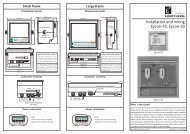
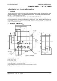
MOUNTING REQUIREMENTS5) with a screwdriver, turn the screws with a torque betweenThis instrument is intended for permanent installation,0.3 and 0.4 Nm.Screwfor indoor use only, in an electrical panel whichbracketencloses the rear housing, exposed terminals andwiring on the back.Select a location, for instrument mounting, whereminimum vibrations are present and the ambienttemperature is within 0 and 50 °C (32 and 122 °F).The instrument can be mounted on a panel up to 15mm thick with a cutout of 92 x 45 mm (<strong>PKP</strong>) or 92 x92 mm (<strong>MKP</strong>).For outline and cutout dimensions refer to Fig. 2.Gasket Panel GasketThe surface texture of the panel must be better bracketsthan 6,3 µm.ScrewsThe instrument is shipped with rubber panelgasket.To assure the IP65 and NEMA 4 protection, insertthe panel gasket between the instrument and thepanel as shown in fig. 1.While holding the instrument against the panelproceed as follows:1) insert the gasket in the instrument case;2) insert the instrument in the panel cutout;3) pushing the instrument against the panel; Screw4) insert the mounting brackets as shown in fig.1;Fig. 1bracket Panel1XKP-1-D1.pmd 125/05/2006, 11.28
OUTLINE AND CUT OUTDIMENSIONSFig. 2.AOUTLINE AND CUT-OUT DIMENSIONS FOR <strong>PKP</strong> MODEL2XKP-1-D1.pmd 225/05/2006, 11.28
Fig. 2.BOUTLINE AND CUT-OUT DIMENSIONS FOR <strong>MKP</strong> MODEL3XKP-1-D1.pmd 325/05/2006, 11.28
CONNECTION DIAGRAMSConnections are to be made with the instrumenthousing installed in its proper location.A) MEASURING INPUTSNOTE: Any external component (like zenerbarriers etc.) connected between sensor and inputterminals may cause errors in measurement due toexcessive and/or not balanced line resistance orpossible leakage currents.Fig. 3REAR TERMINAL BLOCK4XKP-1-D1.pmd 425/05/2006, 11.28
A.1) TC INPUTA.2) RTD INPUT+1RTDRTD_3Shield+1_3Shield43 1431Fig. 4 THERMOCOUPLE INPUT WIRINGNOTES:1) Don’t run input wires together with power cables.2) For TC wiring use proper compensating cable preferableshielded.3) When a shielded cable is used, it should be connected atone point only.Fig. 5 RTD INPUT WIRINGNOTES:1) Don’t run input wires together with power cables.2) Pay attention to the line resistance; a high line resistancemay cause measurement errors.3) When shielded cable is used, it should be grounded at oneside only to avoid ground loop currents.4) The resistance of the 3 wires must be the same.5XKP-1-D1.pmd 525/05/2006, 11.28
A.3) LINEAR INPUT1313+ mA,mVor_ VShield+_GmAmVorV3) When shielded cable is used, it should be grounded at oneside only to avoid ground loop currents.4) The input impedance is equal to:< 5 Ω for 20 mA input> 1 MΩ for 60 mV input> 200 kΩ for 5 V input> 400 kΩ for 10 V inputA.4) 2, 3 AND 4-WIRE TRANSMITTER INPUT13_+TXFig. 6 mA, mV AND V INPUTS WIRINGNOTES:1) Don’t run input wires together with power cables.2) Pay attention to the line resistance; a high line resistancemay cause measurement errors.7Shield11Fig. 7.A INPUTS WIRING FOR 2-WIRE TRANSMITTER6XKP-1-D1.pmd 625/05/2006, 11.28
1Out+13OutPWR+TX3711Out_PWR+PWR_TX7GNDShield11ShieldFig. 7.B INPUTS WIRING FOR 3-WIRE TRANSMITTERFig. 7.C INPUTS WIRING FOR 4-WIRE TRANSMITTERNOTES:1) Don’t run input wires together with power cables.2) Pay attention to the line resistance; a high line resistancemay cause measurement errors.3) When shielded cable is used, it should be grounded at oneside only to avoid ground loop currents.4) The input impedance is lower than 5 Ω (20 mA input)7XKP-1-D1.pmd 725/05/2006, 11.28
B) AUXILIARY INPUT56+ mAor_ V4) When shielded cable is used, it should be grounded at oneside only to avoid ground loop currents.5) The input impedance is equal to:< 5 Ω for 20 mA input> 200 kΩ for 5 V input> 400 kΩ for 10 V input56Fig. 8 AUXILIARY INPUT WIRINGShield+_GmAorVC) LOGIC INPUTS8910DIG. 1DIG. 2DIG. 3NOTES:1) This input is not isolated from measuring input. A double orreinforced insulation between instrument output and powersupply must be assured by the external instrument.2) Don’t run input wires together with power cables.3) Pay attention to the line resistance; a high line resistancemay cause measurement errors.811Fig. 9.A - LOGIC INPUTS DIG 1, 2, 3 WIRINGXKP-1-D1.pmd 825/05/2006, 11.28
56IN 156IN 5575859IN 2IN 3IN 4575859IN 6IN 7IN 86060Fig. 9.B - LOGIC INPUTS IN 1, 2, 3 and 4 WIRINGFig. 9.C - LOGIC INPUTS IN 5, 6, 7 and 8 WIRINGNOTES:1) Do not run logic input wiring together with power cables.2) Use an external dry contact capable of switching 0.5 mA,5 V DC.3) The instrument needs 110 ms to recognize a contact statusvariation.4) The logic inputs are NOT isolated by the measuring input.A double or reinforced insulation between instrument inputand power line must be assured by the external element.9XKP-1-D1.pmd 925/05/2006, 11.28
D) CURRENT TRANSFORMER INPUT1415Currenttransformer3) The minimum active period to perform this measurement isequal to 120 ms.4) The input impedance is equal to 20 Ω.LoadFig. 10 CURRENT TRANSFORMER INPUT WIRINGThis input allows you to measure and display the currentrunning in the load, driven by a time proportional control output,during the ON and OFF periods of the output cycle time. By thisfeature it is also available the "Output failure detection" function(see page 110).NOTES:1) This input is not isolated from measuring input.2) Do not run current transformer input wiring together with ACpower cables.10XKP-1-D1.pmd 1025/05/2006, 11.28
E.1) RELAY OUTPUTSOUT 12324NCCThe outputs from OUT 1 to OUT 4 are equipped with relayshaving contact rating equal to 3A/250V AC on resistive load.WARNING: When OUT 3 and 4 are used as independent relayoutputs the addition of the two currents must not exceed 3 A.25NO26OUT 2 272829OUT 330OUT 431NCCNONO - OUT 3C - OUT 3/4NO - OUT 4OUT 10OUT 11OUT 12OUT 13OUT 14COMMON616263646566NO OUT 10NO OUT 11NO OUT 12NO OUT 13NO OUT 14COMMONFig. 11.A RELAY OUTPUTS 1,2,3 and 4 WIRING11Fig. 11.B RELAY OUTPUTS 10 to 14 WIRINGXKP-1-D1.pmd 1125/05/2006, 11.28
OUT 15OUT 16OUT 17OUT 18OUT 19COMMON505152535455NO OUT 15NO OUT 16NO OUT 17NO OUT 18NO OUT 19COMMONGENERAL NOTES ABOUT RELAY OUTPUT WIRING1) To avoid electrical shock, connect power line at the end ofthe wiring procedure.2) For power connections use No 16 AWG or larger wires rated forat last 75 °C.3) Use copper conductors only.4) Don’t run input wires together with power cables.For all relay outputs, the number of operations is 1 x 10 5 atspecified rating.All relay contacts are protected by varistor against inductive loadwith inductive component up to 0.5 A.The following recommendations avoid serious problems whichmay occur, when using relay output for driving inductive loads.Fig. 11.C RELAY OUTPUTS 15 to 19 WIRINGThe outputs from OUT 10 to 19 are equipped with relays havingcontact rating equal to 0.5A/250V AC on resistive load.INDUCTIVE LOADSHigh voltage transients may occur switching inductive loads.Through the internal contacts these transients may introducedisturbances which can affect the performance of theinstrument.For all the outputs, the internal protection (varistor) assures acorrect protection up to 0.5 A of inductive component.12XKP-1-D1.pmd 1225/05/2006, 11.28
The same problem may occur when a switch is used in serieswith the internal contacts as shown in Fig. 12.Fig. 12 EXTERNAL SWITCH IN SERIES WITH THEINTERNAL CONTACTIn this case it is recommended to install an additional RCnetwork across the external contact as shown in Fig. 12The value of capacitor (C) and resistor (R) are shown in thefollowing table.LOAD(mA)
NOTE: This output is not isolated.A double or reinforced insulation between instrument outputand power supply must be assured by the external solid staterelay.E.3) TRIAC OUTPUTSOUT 12423LineLoadSwitching mode: isolated zero crossing type.Rated current: from 50 mA to 1 A.Rated voltage: from 24 V RMSto 240 V RMS-10 % +15 % (50/60Hz)Load type: resistive load onlyNOTES 1) To avoid electrical shock, connect power line atthe end of the wiring procedure.2) For power connections use No 16 AWG or largerwires rated for at last 75 °C.3) Use copper conductors only.4) Don’t run input wires together with power cables.5) This output is not fuse protected. Please, provide itexternally using a fuse with a I 2 t equal to128.27LineOUT 226LoadFig. 14 TRIAC OUTPUT WIRING14XKP-1-D1.pmd 1425/05/2006, 11.28
E.4) SERVOMOTOR OUTPUT293031121314 (Open the valve)Powerline (Close the valve)Servomotor (Open)Feedbackpotentiometer (Close)ShieldThe two relay output must be interlocked (see chapter"Preliminary hardware setting" paragraph "Out 3 and 4selection").NOTES:1) Before connecting the instrument to the power line, make surethat line voltage and the load current are in accordance with thecontact rating (3A/250V AC on resistive load).2) To avoid electric shock, connect power line at the end of thewiring procedure.3) For servomotor connections use No 16 AWG or larger wiresrated for at last 75 °C.4) Use copper conductors only.5) Don’t run input wires together with power cables.6) For feedback potentiometer, use shielded cable with the shieldconnected to the earth at one point only.7) The relay outputs are protected by varistors againstinductive load with inductive component up to 0.5 A.Fig. 15 SERVOMOTOR OUTPUT WIRING15XKP-1-D1.pmd 1525/05/2006, 11.28
E.5) ANALOG OUTPUTS+16OUT 5 _17+_20 mA18OUT 619+_+_20 mAShieldShield18++16OUT 517+_+_20 mAOUT 619__G20 mAGFig. 16.B OUTPUT 6 WIRINGFig. 16.A OUTPUT 5 WIRINGNOTE:1) Do not run analog output wirings together with AC powercables.2) Out 5 and 6 are isolated outputs.3) The maximum load is equal to 600 Ω.16XKP-1-D1.pmd 1625/05/2006, 11.28
F) SERIAL INTERFACEINSTRUMENT222120A/A'B/B'COMMONA'/AB'/BMASTER3) The EIA standard establishes that by RS-485 interface it ispossible to connect up to 30 devices with one remote masterunit.The serial interface of these instruments is based on “Highinput impedance” transceivers; this solution allows you toconnect up to 127 devices (based on the same transceivertype) with one remote master unit.Fig. 17 - RS-485 WIRINGThe cable length must not exceed 1.5 km at 9600 BAUD.NOTES:1) This is an isolated RS-485 serial interface.2) The following report describes the signal sense of thevoltage appearing across the interconnection cable asdefined by EIA for RS-485.a) The ” A ” terminal of the generator shall be negative withrespect to the ” B ” terminal for a binary 1 (MARK or OFF) state.b) The ” A ” terminal of the generator shall be positive withrespect to the ” B ” terminal for a binary 0 (SPACE or ON).17XKP-1-D1.pmd 1725/05/2006, 11.28
PRELIMINARY HARDWARE SETTINGSHow to remove the instrument from its case1) Switch off the instrument.2) Push gently the lock A on the right.3) While the lock A is maintained out, slide out the right side ofthe instrument (see fig. 19.a)4) Push gently the lock C on the left.5) While the lock C is maintained out, slide out the instrument(see fig. 19.b)DBCADFig. 19.a BFig. 19.b19XKP-1-D1.pmd 1925/05/2006, 11.28
OUTPUT 3 AND 4 SELECTIONOutput 3 and 4 can be set as:- 2 independent relay outputs- 1 servomotor output with interlocked contact.Set J204 (see fig. 21) and J205 (see fig. 20) according to thedesired output type as shown in the following table.Output J 204 J 205Relay close openServo open closeNOTE: when the servomotor close loop or the servomotor openloop with valve position indication outputs is required, it will benecessary to set also V301 (see "IN CT/Feedback selection"paragraph)J204IN CT / FEEDBACK SELECTIONThis instrument can use the "IN CT" input or the "Feedback"input; the two inputs are not contemporarily.The current transformer input allows you to measure anddisplay the current running in a load driven by a time proportionalcontrol output during the ON and OFF periods of theoutput cycle time. By this feature it is also available the "Outfailure detection" function (see page 111).The feedback input is used when the servomotor close loop orthe servomotor open loop with valve position indication outputsis required.Fig.2121XKP-1-D1.pmd 2125/05/2006, 11.28
To select the desired input type, set V301 (see fig. 20) asdetailed in the following table:Input V301.1 V301.2 V301.3 V301.4IN CT ON OFF ON ONFeedback OFF ON OFF ONKY101KY103ON DIP1 2 3 4V101OPTION CHECKThis instrument can be supplied with several options.Two integrated circuits (KY101 and KY103), located as shownin fig. 22 and inserted in a socket, give you the possibility toverify if your instrument is equipped with the desired option.When KY101 is present the auxiliary input and the digital inputsare present.When KY103 is present the auxiliary power supply option ispresent.Fig. 2222XKP-1-D1.pmd 2225/05/2006, 11.28
Operative mode and Hardware lockBy V101 (see fig 22) it is possible to select one of the followingoperative modes:a) run time mode without configuration modeb) run time and configuration modesc) security code setting modeSet V101 according to the following table:Modes V101.1 V101.2 V101.3 V101.4a OFF ON ON ONb OFF ON OFF ONc OFF ON OFF OFFAll the others switch combinations are reserved.SECURITY CODE SETTING MODEGeneral notesThe instrument parameters are divided in two families and eachfamily is divided in groups.- The first family encompasses all the run time parameters.- The second family comprises all the configuration parameters.A specific security code enables the parameter modification ofeach family.For run time parameters, it is possible to select which groups ofthem will be protected by the security code and in this case, itis necessary to set the run time security code before to modifyone or more parameters of a protected group.The configuration security code protects all configurationparameters and it will be necessary to set the configurationsecurity code before to start the configuration parametersmodification.For configuration parameters an hardware lock is alsoavailable.23XKP-1-D1.pmd 2325/05/2006, 11.28
Security code setting:1) Remove the instrument from its case.2) Set the internal dip switch V101 as follows:- V101.1 = OFF - V101.2 = ON- V101.3 = OFF - V101.4 = OFF3) Re-insert the instrument.4) Switch on the instrument. The display will show:The upper display shows that the security code setting modeis selected while the lower display shows the firmwareversion.5) Push the FUNC pushbutton.Run time security codeThe display will show:Note: the middle display shows the current status of the runtime security code ("0", "1" or "On").By and push-button, set "S.run" parameter as follows:0 No protection (it is ever possible to modify all runtime parameters);1 ever protected (it is never possible to modify a runtime parameter);from 2 to 250 security code for run time parameterprotection.NOTES:1) The selected value of a security code cannot be displayedanymore and, coming back to the "S.run" parameter, thedisplay will show :- "On" when "S.run" is different from 0 or 1- "0" when "S.run" is equal to 0- "1" when "S.run" is equal to 1.When the security code is forgotten, a new value can be set.2) When "S.run" is different from 0 or 1, the "run time default "24XKP-1-D1.pmd 2425/05/2006, 11.28
and the "run time hidden" groups are ever protected bysecurity code.Configuration security codeThe display will show:Run time groups protected by security codeThe display will show:By this parameter it is possible to set if the run time group 2 willbe protected or not by the run time security code.By and push-button, set "Gr2" parameter as follows:nO No protection (it is always possible to modify run timegroup 2 parameters)Yes the run time group 1 parameter modification will beprotected by security code.Push the FUNC push-button; the instrument memorizes thenew setting and goes to the next parameter.NOTES:1)This selection may be carried out only if a run timesecurity code has been set (from 2 to 250).2) The above described selection may be repeated forall groups of the run time mode.Note: the middle display shows the current status of theconfiguration security code ("0", "1" or "On").By and push-button, set "S.CnF" parameter as follows:0 No protection (it is ever possible to modify allconfiguration parameters);1 ever protected (it is never possible to modify aconfiguration parameter);from 2 to 250 security code for configuration parameterprotection.NOTE:the selected value of a security code cannot bedisplayed anymore and, coming back on the "S.CnF"parameter, the display will show "On" when "S.CnF" isdifferent from 0 or 1, "0" when "S.CnF" is equal to 0,"1" when "S.CnF" is equal to 1.When the security code is forgotten, a new value canbe set.25XKP-1-D1.pmd 2525/05/2006, 11.28
NOTE:at the end of the security code setting procedure, setV101 according to the desired operative mode (see"Operative mode and hardware lock" paragraph).RUN TIME AND CONFIGURATION MODESThe hardware selection described in "Operative mode andhardware lock" paragraph allows you to start one of thefollowing operative modes:- configuration mode.- run time modeThe run time mode can be divided as follows:- Run time mode as controller- Run time mode as programmerAt power up, the instrument starts in the same mode (configurationor run time) it was prior to the power OFF.General note about graphic symbols used for mnemoniccode visualization.The instrument displays some characters with special symbols.The following table shows the correspondence between thesymbols and the characterssymbol character symbol character" " k " " W" " m " " Z" " V " " J26XKP-1-D1.pmd 2625/05/2006, 11.28
Keyboard descriptionMENU = is used to select a parameter groupFUNC = when the instrument is in "normal display mode" itchanges the indication on the lower display (see"display function"). During parameter modification, it allows you tomemorize the new value of the selected parameterand go to the next parameter (increasing order).MAN = when the instrument is in "normal display mode",pushing MAN push-button for more than 1 s, it ispossible to enable or disable the manual function. During parameter modification, it allows you toscroll back the parameters and groups withoutmemorizing the new setting. = During parameter modification, it allows you toincrease the value of the selected parameter During MANUAL mode, it allows you to increasethe output value. During program execution with the instrument inHOLD status, it allows you to shift forward theprogram with a speed 60 time faster than normal. = During parameter modification, it allows you todecrease the value of the selected parameter During MANUAL mode, it allows to decrease theoutput value. During program execution with the instrument inHOLD status, it allows you to shift backward theprogram with a speed 60 time faster than normal.RUN = allows:- to rapidly select the program to execute.- to start program execution,- to toggle from RUN to HOLD mode or viceversa(pushing for more than 3 s and less than 10 s) or- to ABORT program execution (pushing for morethan 10 s).RUN + = during program editing are used to add a programsegment (see paragraph "How to edit a program")RUN + = during program editing are used to delete aprogram segment (see paragraph "How to edit aprogram")RUN + MENU = during program editing are used to jump tothe first parameter of the next segment (seeparagraph "How to edit a program")RUN + MAN = during program editing are used to check theselected program (see paragraph "How to check aprogram")27XKP-1-D1.pmd 2725/05/2006, 11.28
+MENU= are used to start the lamp test function (seeparagraph "Lamp test")+FUNC or +FUNCDuring parameter modification they allow you toincrease/decrease the value under modificationwith higher rate.+MAN or +MAN During parameter modification they allow you tojump to the max or min programmable value. When the instrument operates as programmer inHOLD mode, they allow to jump to the beginning ofthe next segment or to the end of the previous one.NOTES:1) All the actions explained above which require the pressure oftwo or more push-buttons must follow exactly the pushbuttonsequence shown.2) A 10 or 30 seconds time out (see "t.out" [C.I10]) can beselected for parameter modification during run time mode.If, during parameter modification, no push-button isdepressed for more than 10 (30) seconds, the instrumentgoes automatically to the “normal display mode” and theeventual modification of the last parameter will be lost.CONFIGURATION MODESwitch on the instrument.The instrument will start in the same way it was prior to thepower down (configuration mode or run time mode)If the instrument starts in configuration mode, push the MENUpushbutton and go to the "Configuration group 1" (see page31).If the instrument starts in run time mode, by keeping depressedthe MENU push-button for more than 5 seconds the instrumentwill show:NOTES:1) The upper display shows the selected parameter family.2) The middle display shows the selected action.3) The lower display shows the firmware version.4) If no push-button is depressed for more than 10 s (or 30 saccording to "CnF.6" "t.out" [time out selection" C.I10]parameter setting), the instrument returns automatically tothe normal display mode.28XKP-1-D1.pmd 2825/05/2006, 11.28
By or push-button it is possible to select between:= (monitor) this selection allows you to monitor butnot to modify the value assigned to theconfiguration parameters= (modify) this selection allows you to monitor andto modify the value assigned to the configurationparameters.NOTES:1) During monitor mode, the instrument continues to operate asin run time mode.2) When modify mode is started, the instrument stops thecontrol and:- sets to OFF the control outputs;- turns to OFF the bargraph displays (<strong>MKP</strong> only);- sets analog retransmissions to the retransmitted initialscale value;- sets alarms in no alarm condition;- sets to OFF the events;- disables the serial link;- the time out will be removed.3) When the modify mode is disabled by V101 (V101.3), the or push-button pressure has no effect.MONITOR MODEDuring the run time mode, it is possible to monitor but notmodify all configuration parameters.When it is desired to verify the instrument configuration,proceed as follows:1) Push the MENU push-button for more than 5 seconds: thedisplay will show:.2) Push the MENU push-button the display will show:it shows that configuration group 1 is selected and itencompasses all the input parameters.The configuration parameter "Monitor mode" follows the"Modify mode" sequence.NOTES:1) During monitor mode, the instrument continues to operate asin run time mode.29XKP-1-D1.pmd 2925/05/2006, 11.28
CnF. 12) During monitor mode, if no push-button is depressed formore than 10 s (or 30 s according to "t.out" [C.I10]parameter setting), the instrument returns automatically tothe normal display mode.MODIFY MODE1) By or push-button select the modify mode.2) Push the MENU push-button.If a security code is applied to the configuration parameter,the instrument will show:The modify mode is started.This display allows you to load the default configurationparameter.For more details see chapter "Default parameter" (seeAppendix A).4) By or push-button select the OFF indication and pushthe MENU push-button.The display will show:3) By and push-button set a value equal to the securitycode assigned to the configuration mode (see "Configurationsecurity code " at page 25).If the code is different from the security code, the instrumentautomatically returns to the first configuration displayotherwise the display will show:This is the starting display of the first group of configurationparameters.NOTES:1) In the following pages we will describe all the parameters.The instrument, however, will show only the parametersrelated to the specific hardware and in accordance with the30XKP-1-D1.pmd 3025/05/2006, 11.28
specific instrument configuration (i.e. setting OUT 3 differentfrom servo, all the parameters related to servomotor outputwill be skipped).2) During configuration parameters modify mode, the upperdisplay shows the selected parameter group, the lowerdisplay shows the mnemonic code of the selected parameterwhile the central display shows the value or status assignedto the selected parameter.3) For an easy consultation of this manual, a sheet named"Reference parameter guide" with all the parametervisualizations is enclosed.The group (column) of configuration parameters areidentified by the "C" letter followed by A, b, etc.The "code" formed by the column and row (example [C.d03])is reported, in the user manual, before each parameterdescription and allows you to quickly find out the respectiveparameter.When it is desired to exit from configuration modify modeproceed as follows:a) Push "MENU" push-button until the "Configuration groupEND is displayed.b) Pushing ”” or “” push-button select the "YES" indication.c) Push “MENU” push-button. The instrument terminates theconfiguration modify mode, it preforms an automatic resetand restarts in the run time mode.31CONFIGURATION GROUP 1 [C.dxx]MAIN AND AUXILIARY INPUT CONFIGURATIONPush the FUNC push-buttonRange:50 Hz60 Hz- Line frequency - [C.d01]- Main input type and range - [C.d02]Ranges:* 1 = TC L From -100 to 900 °C* 2 = TC J From -100 to 1000 °C* 3 = TC K From -100 to 1370 °C* 4 = TC T From -200 to 400 °C* 5 = TC U From -200 to 600 °C* 6 = TC E From -100 to 800 °C7 = TC N From -100 to 1400 °CCnF. 1XKP-1-D1.pmd 3125/05/2006, 11.28
CnF. 18 = TC S From - 50 to 1760 °C9 = TC R From - 50 to 1760 °C10 = TC B From 0 to 1820 °C11 = TC G (or W) From 0 to 2300 °C12 = TC D (or W3) From 0 to 2300 °C13 = TC C (or W5) From 0 to 2300 °C14 = TC Ni-Ni18%Mo From 0 to 1100 °C* 15 = RTD Pt100 From -200 to 850 °C16 = TC L From -150 to 1650 °F17 = TC J From -150 to 1830 °F18 = TC K From -150 to 2500 °F19 = TC T From -330 to 750 °F20 = TC U From -330 to 1110 °F21 = TC E From -150 to 1470 °F22 = TC N From -150 to 2550 °F23 = TC S From - 60 to 3200 °F24 = TC R From - 60 to 3200 °F25 = TC B From 32 to 3300 °F26 = TC G ( or W) From 0 to 4170 °F27 = TC D (or W3) From 0 to 4170 °F28 = TC C (or W5) From 0 to 4170 °F29 = TC Ni-Ni18%Mo From 0 to 2000 °F* 30 = RTD Pt100 From -330 to 1560 °F31 = Linear From 0 to 20 mA32 = Linear From 4 to 20 mA33 = Linear From 0 to 5 V34 = Linear From 1 to 5 V35 = Linear From 0 to 10 V36 = Linear From 2 to 10 V37 = Linear From 0 to 60 mV38 = Linear From 12 to 60 mV* For these ranges it is possible to select a read-out with onedecimal figure but the instrument could not display ameasure lower than -199.9 or higher than 999.9 and theinput range will be limited by it.NOTES:1) When a linear input is selected, the instrument automaticallysets the "readout initial scale value" [C.d05] equal to 0 andthe "readout full scale value" [C.d06] equal to 40002) When input type has been changed, the instrumentautomatically forces:- the "ñ.In.L" [C.d05], "SS.th" [C.I09] and "brG.L" [C.I03]parameters to the new initial scale value,- the "ñ.In.H" [C.d06] and "brG.H" [C.I04] parameter to thenew full scale value and- the "ñ.In.d" [C.d03] parameter to "no decimal figure".32XKP-1-D1.pmd 3225/05/2006, 11.28
- Decimal point position - [C.d03]Ranges: ----. = no decimal figure---.- = one decimal figure--.-- = two decimal figures-.--- = three decimal figuresNOTES:1) For main input type 1 to 6, 15 and 30 only the "no decimalfigure" and "one decimal figure" are selectable, the inputrange is limited within -199.9 and 999.9 and it acts as aninput type changement.2) For main input type 7 to 14 and 16 to 29 this parameter isnot available.3) For linear input types (from 31 to 38) all positions areavailable.- Square root extraction for main input -[C.d04]Ranges: dIS = square root extraction disabledEnb = square root extraction enabledNOTES:1) This parameter is available only for main input type 31 to 38.2) When the square root extraction is enabled the values of thefollowing parameters:- "ñ.In.L" (read-out - initial scale value [C.d05]),- "ñ.In.H" (read-out - full scale value [C.d06]),- "brG.L" (bargraph - initial scale value [C.I03]),- "brG.H" (bargraph - full scale value [C.I04])- "SS.th" (threshold to enable the soft start [C.I09])must be positive or equal to zero.Enabling the square root extraction the instrument verifiesthe current value of the "ñ.In.L", "ñ.In.H", "brG.L", "brG.H"and "SS.th" parameters and force to zero the eventualnegative values.- Read-out- initial scale value - [C.d05]Ranges: - from -1999 to 9999 for linear input (Input range 31 to38),- from 0 to 9999 for linear input with square rootextraction,- from initial range value to "ñ.In.H" (read-out- fullscale value C.d06]) for TC/RTD inputNOTES:1) The Read-out initial scale value can be higher than theRead-out - full scale value.CnF. 133XKP-1-D1.pmd 3325/05/2006, 11.28
CnF. 12) Changing the value of this parameter, the "brG.L" (bargraph- initial scale value [C.I03]) and "rL" (set point low limit[r.E12]) parameters will be realigned to it.If a linear input is selected, also the “SS.th” (threshold forsoft start [C.I09]) will be realigned to it.- Read-out- full scale value - [C.d06]- Offset on the main input - [C.d07]Ranges: from -500 to 500.NOTE: the decimal point will be automatically positioned asselected for the main input.Read-out Real curveRanges: - from -1999 to 9999 for linear input (Input range 31 to38),- from 0 to 9999 for linear input with square rootextraction,- from "ñ.In.L" (read-out- initial scale value [C.d05]) tofull range value for TC/RTD input.NOTES:1) Changing the value of this parameter, the "brG.H" (bargraph- full scale value [C.I04]) and "rH" (set point high limit [r.E13])parameters will be realigned to it.2) The programmed input span, in absolute value, must begreater than:300 °C or 550 °F for TC inputs100°C or 200 °F for RTD inputs100 digits for linear inputs.OFStAdjustedcurveInput- Filter on the displayed value - [C.d08]Ranges: from 0 (no filter) to 8 seconds.NOTE: this is a first order digital filter applied to the read-out ofthe main input.34XKP-1-D1.pmd 3425/05/2006, 11.28
- Auxiliary input function - [C.d09]Range: nonE = Input not usedbIAS = Input used as bias for local set pointNOTES:1) When auxiliary input option is not mounted the middledisplay will show “no.Pr” (not present).2) When "bIAS" is selected, the instrument adds to the local setpoint the value measured by the auxiliary input and scaledby "A.In.L" [C.d11] and "A.In.H" [C.d12] parameters.- Initial scale read-out of the auxiliary input- [C.d11]This parameter is available only when auxiliary input isconfiguredRange: from -1999 to 9999NOTE: the decimal point will be automatically positioned asselected for the main input.CnF. 1- Auxiliary input type - [C.d10]This parameter will be skipped when the auxiliary input optionis not mounted or "A.In.F" (auxiliary input function [C.d09]) isequal to "nonE".Range: 0-20 = 0−20 mA4-20 = 4−20 mA0- 5 = 0− 5 V1- 5 = 1− 5 V0-10 = 0−10 V2-10 = 2−10 V- Full scale read-out of the auxiliary input- [C.d12]This parameter is available only when auxiliary input isconfigured.Range: from -1999 to 9999NOTE: the decimal point will be automatically positioned asselected for the main input.35XKP-1-D1.pmd 3525/05/2006, 11.28
CnF. 2- Filter on auxiliary input - [C.d13]This parameter is available only when auxiliary input isconfiguredRanges: from 0 (no filter) to 8 seconds.NOTE: this is a first order digital filter applied to the measuredvalue made by the auxiliary input.CONFIGURATION GROUP 2 [C.Exx]OUTPUTS CONFIGURATIONGeneral note about configuration group 1Exiting from the configuration group 1 the instrument automaticallyverifies the programmed span for the linear input.If it is wrong, the device will show:Push the FUNC pushbutton more times until the "ñ.In.L"[C.d05] or "ñ.In.H" [C.d06] are displayed and modify their valuein order to respect the minimum read-out span (see NOTE 2 ofthe "ñ.In.H" [C.d06] parameter).- OUT 1 function - [C.E01]Range: nonE = Output not usedñAin = Time proportional main control outputSECn = Time proportional secondary control outputALr.1 = Alarm 1 outputEun.1 = Event 1 outputNOTE: for Event description see "Event 1function" [C.H.09] parameter.36XKP-1-D1.pmd 3625/05/2006, 11.28
- OUT 2 function - [C.E02]Range: nonE = Output not usedñAin = Time proportional main control outputSECn = Time proportional secondary control outputALr.2 = Alarm 2 outputEun.2 = Event 2 output- OUT 3 function - [C.E03]When the option is not mounted the middle display will show“no.Pr” (not present).Range: nonE = Output not usedñAin = Time proportional main control outputSECn = Time proportional secondary control outputALr.3 = Alarm 3 outputEun.3 = Event 3 outputñC.Sñ = Servomotor control drive as main controloutputSC.Sñ= Servomotor control drive as secondary controloutput- OUT 4 function - [C.E04]Range: nonE = Output not usedñAin = Time proportional main control outputSECn = Time proportional secondary control outputALr.4 = Alarm 4 outputEun.4 = Event 4 outputNOTES:1) When option is not mounted the middle display will show“no.Pr” (not present).2) When servomotor control drive is hardware selected (see"Output 3 and 4 selection" at pag. 21), the OUT 4 can beused only as servomotor drive and this parameter will not beshown.- Servomotor type - [C.E05]This parameter will be available only when servomotor controldrive is configured (“CnF.2 - O3.Fn” [C.E03]= “ñC.Sñ” or“SC.Sñ”).Range: CLSd = Close loop typeNOTE: this selection is available only iffeedback circuitry is mounted and selected.OPEn = Open loop type.CnF. 237XKP-1-D1.pmd 3725/05/2006, 11.28
CnF. 2- Valve position indication - [C.E06]This parameter will be displayed only when open loopservomotor control drive output is configured.Range: Fb = The valve position is measured and displayedno.Fb = The valve position is not measuredNOTE: If the feedback option is not mounted, this parameterwill be forced to “no.Fb” (no feedback).- OUT 5 function - [C.E07]Range: nonE = Output not usedñAin = Main control output (linear)SECn = Secondary control output (linear)PV.rt = Process variable retransmissionSP.rt = Operative set point retransmissionNOTE: When the option circuitry is not mounted the middledisplay will show “no.Pr” (not present).- OUT 5 range - [C.E08]This parameter will be available only when Out 5 is configured("O5.Fn" [C.E07] different from "nonE")Range: 0-20 = 0÷20 mA4-20 = 4÷20 mA- OUT 5 retransmission initial scale value- [C.E09]This parameter will be available only when Out 5 function[C.E07] is configured as “PV.rt” or “SP.rt”Range: From -1999 to 9999NOTES:1) Decimal point is positioned as previously selected at “CnF.1- ñ.In.d” [C.d03])2) The OUT 5 retransmission initial scale value can be higherthan OUT 5 retransmission full scale value [C.E.10].38XKP-1-D1.pmd 3825/05/2006, 11.28
- OUT 5 retransmission full scale value- [C.E10]This parameter will be available only when Out 5 function[C.E07] is configured as “PV.rt” or “SP.rt”Range: From -1999 to 9999NOTE: Decimal point is positioned as previously selected at“CnF.1 - ñ.In.d” [C.d03])- OUT 5 filter on the retransmitted value- [C.E11]This parameter will be available only when OUT 5 is configuredas process variable retransmission ("O5.Fn" [C.E07] is equal to“PV.rt”).Range: From 0 (no filter) to 8 secondsNOTE: this is a first order digital filter applied to theretransmitted output value.- OUT 6 function - [C.E12]Range: nonE = Output not usedñAin = Main control output (linear)SECn = Secondary control output (linear)PV.rt = Process variable retransmissionSP.rt = Operative set point retransmissionNOTE: When the option circuitry is not mounted the middledisplay will show “no.Pr” (not present).- OUT 6 range - [C.E13]This parameter will be available only when Out 6 is configured("O6.Fn" [C.E12] different from "nonE")Range: 0-20 = 0÷20 mA4-20 = 4÷20 mA- OUT 6 retransmission initial scale value- [C.E14]This parameter will be available only when Out 6 function[C.E12] is configured as “PV.rt” or “SP.rt”Range: From -1999 to 9999NOTES:1) Decimal point is positioned as previously selected at “CnF.1- ñ.In.d” [C.d03])2) The OUT 6 retransmission initial scale value can be higherthan OUT 6 retransmission full scale value [C.E.15].CnF. 239XKP-1-D1.pmd 3925/05/2006, 11.28
CnF. 2- OUT 6 retransmission full scale value- [C.E15]This parameter will be available only when Out 6 function[C.E12] is configured as “PV.rt” or “SP.rt”Range: From -1999 to 9999NOTE: Decimal point is positioned as previously selected at“CnF.1 - ñ.In.d” [C.d03])General note about configuration group 2I) Exiting from the configuration group 2 the instrumentautomatically verifies the congruence of all parameters.If a wrong setting is detected, the device will show:- OUT 6 filter on the retransmitted value- [C.E16]This parameter will be available only when OUT 6 is configuredas process variable retransmission ("O6.Fn" [C.E12] is equal to“PV.rt”).Range: From 0 (no filter) to 8 secondsNOTE: this is a first order digital filter applied to theretransmitted output value.Pushing the FUNC pushbutton, verify (and modify ifnecessary) all group 2 parameter settings in order to assurethat the following conditions are respected:a ) Only one of the 6 outputs is configured as main output(“ñAin”)b) Only one of the 6 outputs is configured as secondaryoutput (“SECn”)c) If only one control output is configured, it should be themain control output (“ñAin”)d) The servomotor must be “close loop” type if it is one oftwo control outputs.NOTE: The instrument may be used as an indicator, so that thistest is satisfied even if no output is configured as control output40XKP-1-D1.pmd 4025/05/2006, 11.28
II) Exiting from the configuration group 2 also the followingactions are automatically performed:A) The "Añ.UL” parameter ("Output value for auto to manualtransfer" [C.G04]) will be forced to "bumpless" (“buñ”) if:1) its value is < 0 and only one control output is configured;2) servomotor open loop is configured.B) The “SF.Cn” parameter ("Condition for output safety value"[C.G09]) will be forced to "standard" (“Std.”) if it is notcomplied with configured control output type.C) The “SF.UL” parameter ("Output safety value" [C.G10]) willbe forced to 0 if only one control output is configured and itsvalue is < 0.D ) The “Fd.Fn” parameter ("Out failure detection currentmeasurement" [C.I11]) will be forced to “nonE” if it isassigned to a control output different from a timeproportional output.E ) The “Fd.Ou” parameter ("Out failure detection outputassignment" [C.I13]) will be forced to “nonE” if it isassigned to an output configured as control output.F ) The “IP” parameter ("Integral pre-load" [r.d05]) will be forcedto 50.0 if only one control output is configured and its valueis < 0.CONFIGURATION GROUP 3 [C.Fxx]CONTROL OUTPUT CONFIGURATION- Split range - [C.F01]This parameter will be available only when two control outputsare configured.Range: dIS = Split range feature is not requiredEnb = Split range feature is requiredNOTE about the split range.This function allows you to drive by the same control action,two physical outputs (two actuators) with different bias andgain.CnF. 2 341XKP-1-D1.pmd 4125/05/2006, 11.28
CnF. 3The relation between the Calculated Power Output and theresulting real outputs are shown below:Real PWROutput100 %0 %ACwhere:- for the first split output (MAIN)Bias 1 = -AGain 1 = 100 / (B - A)- For the second split output (SECONDARY)Bias 2 = -CGain 2 = 100 / (D - C)BFirst splitoutput (MAIN)Standard curveSecond splitoutput(Secondary)Calculated100 % PWR OutputDFOR EXAMPLE:Let's suppose that the first split output operates from 0 % to33.3 % of the calculated output while the second one operatesfrom 33.3 % to the 100 % of the calculated output.Real PWROutput100 %Calculated0 %PWR OutputA B e C D33.3 % 100 %Where: A = 0 %B = C = 33.3 %D = 100 %First splitoutput (MAIN)Standard curveSecond splitoutput(Secondary)42XKP-1-D1.pmd 4225/05/2006, 11.28
We will set:Bias 1 = 0Gain 1 = 100 / (33.3 - 0) = 3Bias 2 = - 33.3Gain 2 = 100 / (100 - 33.3) = 1,5- Main control output bias - [C.F03]This parameter will be available only when the split range isenabled ("SPLt." [C.F01] = "Enb").Range: from -100.0 to 100.0 % of the output span.CnF. 3The bias and gain of the two split outputs are the following:“ñC.bS” [C.F03] is the Bias 1 applied to the main output“ñC.Gn” [C.F02] is the Gain 1 applied to the main output“SC.bS” [C.F05] is the Bias 2 applied to the secondary output“SC.Gn” [C.F04] is the Gain 2 applied to the secondary output- Secondary control output gain - [C.F04]This parameter will be available only when the split range isenabled ("SPLt." [C.F01] = "Enb").Range: from 0.50 to 5.00- Main control output gain - [C.F02]This parameter will be available only when the split range isenabled ("SPLt." [C.F01] = "Enb").Range: from 0.50 to 5.00.- Secondary control output bias - [C.F05]This parameter will be available only when the split range isenabled ("SPLt." [C.F01] = "Enb").Range: from -100.0 to 100.0 % of the output span.43XKP-1-D1.pmd 4325/05/2006, 11.28
CnF. 3- Main control output conditioning - [C.F06]This parameter will be available only when main control outputis configured.Range: norñ = The control output is calculated by the PID.CñPL = The control output is complemented (100-PIDcalculated value).Ouic = The control output is conditioned to match a“QUICK OPENING” flow characteristic.Eou = The control output is conditioned to match an“EQUAL PERCENTAGE” flow characteristic.NOTE about output conditioningSometimes non linear valves are used where a linear valve issuitable.In these cases, it is advisable to linearize the ratio between flowrate and valve travel in order to obtain a better control of theprocess.This instrument allows you to select an output linearization inaccordance with the two most common valve flow characteristics:- Quick opening- Equal percentage.44XKP-1-D1.pmd 4425/05/2006, 11.28
- Main control output in engineering unit- [C.F07]This parameter will be available only when main control outputis configured.Range: nO = Scalable is not requiredYES = Scalable is requiredNOTE: This scaling allows you to display the output value inengineering units instead of in percent.- Main output initial scale readout - [C.F09]This parameter will be available only when "ñ.SCL" ("Maincontrol output in engineering units" [C.F07]) is set to "YES".Range: from -199 to 999NOTE: The Main output initial scale value can be higher thanthe Main output full scale value.CnF. 3- Main output decimal point position - [C.F08]This parameter will be available only when "ñ.SCL" ("Maincontrol output in engineering units" [C.F07]) is set to "YES".Range: ----. = No decimal figure---.- = One decimal figure.--.-- = Two decimal figures.- Main output full scale readout - [C.F10]This parameter will be available only when "ñ.SCL" ("Maincontrol output in engineering units" [C.F07]) is set to "YES".Range: from -199 to 99945XKP-1-D1.pmd 4525/05/2006, 11.28
CnF. 3- Main output auxiliary conditioning - [C.F11]This parameter will be available only when main control outputis configured and “ñC.Cn” ("Main control output conditioning"[C.F06]) is different from “norñ”.Range: bEFr = The functions listed at Note (*) are calculatedbefore to apply the action selected by “ñC.Cn”("Main control output conditioning" [C.F06])parameter.AFtr = The functions listed at Note (*) are calculatedafter to apply the action selected by “ñC.Cn”(“Main control output conditioning” [C.F06])parameter.Note (*)- "Main control output limiters" - for more details see [r.E04]and [r.E05] parameters.- "Main control output max rate of rise" (see [r.E06]).- "Control output display value" - for more details see "Displayfunction during programmer mode" paragraph at pag. 106and [C.F07], [C.F08], [C.F09] and [C.F10] parameters.- "Threshold for alarm on control output value" - for moredetails see [r.F01], [r.F05] [r.F09] and [r.F13] parameters.- The control output value displayed by bargraph.- Secondary control output conditioning- [C.F12]This parameter will be available only when secondary controloutput is configured.Range: norñ = The control output is calculated by the PIDCñPL = The control output is complemented (100-PIDcalculated value)Ouic = The control output is conditioned to match a“QUICK OPENING” flow characteristicEou = The control output is conditioned to match an“EQUAL PERCENTAGE” flow characteristicFor more details see also NOTE about output conditioning atpage 44.46XKP-1-D1.pmd 4625/05/2006, 11.28
- Secondary control output in engineering unit- [C.F13]This parameter will be available only when secondary controloutput is configured.Range: nO = Scalable is not requiredYES = Scalable is requiredNOTE: This scaling allows to display the output value inengineering units instead of in percent.- Secondary control output initial scale value- [C.F15]This parameter will be available only when "S.SCL" ("Secondarycontrol output in engineering units" [C.F13]) is set to "YES".Range: from -199 to 999NOTE: The secondary control output initial scale value can behigher than the secondary control output full scale value.CnF. 3- Secondary control output decimal pointposition - [C.F14]This parameter will be available only when "S.SCL" ("Secondarycontrol output in engineering units" [C.F13]) is set to "YES".Range: ----. = No decimal figure---.- = One decimal figure.--.-- = Two decimal figures.- Secondary control output full scale value- [C.F16]This parameter will be available only when "S.SCL" ("Secondarycontrol output in engineering units" [C.F13]) is set to "YES".Range: From -199 to 99947XKP-1-D1.pmd 4725/05/2006, 11.28
CnF. 43- Secondary output auxiliary conditioning- [C.F17]This parameter will be available only when secondary controloutput is configured and “SC.Cn” ("Secondary control outputconditioning" [C.F12]) is different from “norñ”.Range: bEFr = The functions listed at Note (**) are calculatedbefore to apply the action selected by “SC.Cn”("Secondary control output conditioning"[C.F12]) parameter.AFtr = The functions listed at Note (**) are calculatedafter to apply the action selected by “SC.Cn”(“Secondary control output conditioning”[C.F12]) parameter.General note about configuration group 3Exiting from the configuration group 3 the instrument automaticallytests the "SPLt" parameter (Split range [C.F01]). When"SPLt." parameter is enabled (= "Enb"), the instrumentperforms the following actions:1) If “Añ.UL” parameter ("Output value for AUTO to MANtransfer [C.G04]) is lower than 0, it will be forced to “buñ“.2) If the “SF.UL” parameter ("Output safety value" [C.G10])is lower than zero, it will be forced to zero.3) If the “IP” parameter ("Integral pre-load" [r.d05] is lower thanzero, it will be forced to 50.0.Note (**)- "Secondary control output limiters" - for more details see[r.E08] and [r.E09] parameters.- "Secondary control output max rate of rise" (see [r.E10]).- "Secondary control output display value" - for more detailssee "Display function during programmer mode" paragraphat pag. 106 and [C.F13], [C.F14], [C.F15] and [C.F16]parameters.- "Threshold for alarm on control output value" - for moredetails see [r.F01], [r.F05] [r.F09] and [r.F13] parameters.- The secondary control output value displayed by bargraph.48XKP-1-D1.pmd 4825/05/2006, 11.28
CONFIGURATION GROUP 4 [C.Gxx]AUXILIARY CONTROL CONFIGURATION- Manual function - [C.G03]This parameter will be available only when at least one controloutput is configured.Range: dIS = Manual function disabled.Enb = Manual function may be enabled.CnF. 4- Smart function - [C.G01]This parameter will be available only when at least one controloutput is configured.Range: dIS = Smart function disabled.Enb = Smart function may be enabled.- Control action type - [C.G02]This parameter will be available only when at least one controloutput is configured.Upper display: CnF.4Lower display: Cn.tPRange: Pid = The process is controlled by PID actions.Pi = The process is controlled by PI actions.- Output value for AUTO to MAN transfer- [C.G04]This parameter will be available only when at least one controloutput is configured and manual function is enabled (“ñAn.F”[C.G03] = “Enb”).Range: - from 0.0 % to 100.0 % of the output span if device isconfigured with one control output only;- from -100.0 % to 100.0 % of the output span if deviceis configured with two control outputs (split rangeexcluded).Above the value 100.0 the display shows “buñ.” meaning thatthe transfer from AUTO to MANUAL is bumpless (theinstrument sets for MANUAL mode the same power outputused in AUTO mode).49XKP-1-D1.pmd 4925/05/2006, 11.28
CnF. 4NOTES:1) When open loop servomotor control drive without valveposition indication is configured, this parameter is forced to“buñ.” and it cannot be modified.2) When open loop servomotor control drive with valve positionindication is configured and the transfer from AUTO to MANis required, the instrument is able to reach the valueprogrammed by this parameter using temporarily the valveposition value as a feedback.- MANUAL to AUTO transfer type - [C.G05]This parameter will be available only when at least one controloutput is configured and manual function is enabled (“ñAn.F”[C.G03] = “Enb”)Range: buñ. = Bumpless balance transfer.buñ.b = Bumpless balanceless transfer (the operativeset point is aligned to the measure value).NOTES:1) The “alignment” is not performed if measure is in errorcondition or Remote Set point is selected.2) The selected local set point will be changed even if it issoftware protected.General note about the instrument restartingThe two following parameters are used to set the instrumentrestarting after a power down:- the St.Pr [C.G07] parameter setting is used to the instrumentrestart when a program was running.- the St.Fn [C.G06] parameter setting is used to all the othercases.- Device status at start up when it works ascontroller - [C.G06]This parameter will be available only when at least one controloutput is configured and manual function is enabled (“ñAn.F”[C.G03] = “Enb”).Range: Auto = It starts always in auto modeñan = It starts always in manual mode with poweroutput set to 0.Cnd.A = It starts in the same way it was left prior topower shut down (if in manual mode the poweroutput is set to 0).Cnd.b = It starts in the same way it was left prior topower shut down (if in manual mode the poweroutput will be equal to the last value prior topower shut down).50XKP-1-D1.pmd 5025/05/2006, 11.28
- Program restarting after a power failure- [C.G07]Range: Edit = the program execution will be stopped and theinstrument starts in STAND-BY mode with thevalues programmed by [r.A13] to [r.A17] for thespecific program.SAñE = the program starts from the point in executionleft prior to power shut down.Src = at power up, the instrument operates asfollowsA ) if the measured value is inner to theprogram restart tracking band ("St.tk"[C.G08]) and the instrument was performinga soak, the intrument verifies the trackingband selected for the specific segment and:A.1) if the measured value is inner to thespecific tracking band, the programstarts from the point in execution leftprior to power shut down.A.2) if the measured value is outer to thespecific tracking band, the program willoperate as described at point B).B) if the measured value is inner to the programrestart tracking band ("St.tk" [C.G08]), andthe instrument was performing a ramp, it willstart to search, in the part of the programalready executed, the first set point equal tothe current measured value andB.1)if this point has been found, theprogram execution restart from it.B.2)if this point has not been found, theprogram execution will be stopped andthe instrument starts in STAND-BY modewith the values programmed by the parametersfrom "At the end of program xreset the break event" [r.A13] to "PIDgroup at the end of program x" [r.A17] forthe specific program.C) if the current measured value is outer to theprogram restart tracking band ("St.tk" [C.G08]),the program execution will be stopped and theinstrument starts in STAND-BY mode with thevalues programmed by the parameters from"At the end of program x reset the breakevent" [r.A13] to "PID group at the end ofprogram x" [r.A17] for the specific program.NOTE: When during a program execution, a power failureoccurs, at power up the instrument displays this situationshowing on the upper display "E.600" indication.Push one pusbutton to delete the "E.600" indication.CnF. 451XKP-1-D1.pmd 5125/05/2006, 11.28
CnF. 5 4- Program restart tracking band - [C.G08]This parameter will be available only when "St.Pr" (programrestart after power supply failure [C.G07]) is equal to “Src”.Range: from 0 to 500 digits.- Condition for output safety value - [C.G09]This parameter will be available only when at least one controloutput is configured.Ranges:- When no output is configured as open loop servomotorcontrol, "SF.Cn" can be set as follows:Std. = No safety value (“standard setting” see chapterERROR MESSAGES).Ov.Un = Safety value applied when the instrumentdetects an overrange or underrange conditionof the main input.OvEr = Safety value applied when the instrument detectsan overrange condition of the main input.Undr = Safety value applied when the instrumentdetects an underrange condition of the maininput.- When the open loop servomotor control is configured,"SF.Cn" can be set as follows:Std. = No safety value (“standard setting” see chapterERROR MESSAGES).Cnd.A = When the instrument detects an overrange orunderrange condition of the main input, theservomotor is driven to its high limit position.Cnd.b = When the instrument detects an overrange orunderrange condition of the main input, theservomotor is driven to its low limit position.Cnd.C = When the instrument detects an overrange orunderrange condition of the main input, theaction on servomotor is the complement of“standard” setting.- Output safety value - [C.G10]This parameter will be available only when "SF.Cn" [C.G09] isequal to “Ov.Un”, “OvEr” or “Undr”.Range:- from 0.0 % to 100.0 % if device is configured with onecontrol output;- from -100.0 % to 100.0 % if device is configured with twocontrol outputs (split range excluded).52XKP-1-D1.pmd 5225/05/2006, 11.28
CONFIGURATION GROUP 5 [C.Hxx]DIGITAL INPUT/OUTPUT CONFIGURATION- Logic input "DIG 1" function - [C.H01]This parameter will be available only when input contact optionis fitted.Range: nonE = Input contact not usedru.SL = Input contact used for RUN /HOLD selection.The status is related to the input level (RUNwhen the logic level is "1").NOTE: when an input is programmed as RUN/HOLD selector related with the status, theRUN/HOLD selection by keyboard has noeffect.ru.St = Input contact used for RUN /HOLD selection.The instrument toggles from one status to theother one when the transition selected by"d1.St" [C.H02] is detected.NOTE: for more details about the RUN/HOLDselection, see the related note at pag.54.Pr.Ab = Input contact used for program abort (Abortwhen the logic level is equal to "1").NOTE: for ABORT function only, the inputstatus must be maintained for more than 3seconds.Pr.SL = Input contact used for program selection (formore details see note 2).Au.ñA = Input contact used for Auto/Manual selection(Manual when logic level is “1”)O.LIñ = Input contact used for output limiter activation(Output limited when logic level is “1”)ñ.rSt = Input contact used to reset (acknowledge)alarm (Reset when logic level is “1”)rE.dr = Input contact used for Reverse/Direct controlaction selection (Direct when logic level is “1”)NOTE: When logic input circuits are not mounted the middledisplay will show “no.Pr” (not present).CnF. 553XKP-1-D1.pmd 5325/05/2006, 11.28
CnF. 5Notes about logic inputs used for program selection1) When some logic inputs are programmed as programselectors ("Pr.SL") the instrument will use these logic inputsas a binary code.In the sequence from DIG 1 to 3 and IN 1 to IN 8 theinstrument will considers the first logic input, programmed asprogram selector, as the less significant bit while it willconsider the other inputs with increasing order.For example:DIG 2, DIG 3, IN 3, IN 7 and IN 8 are programmed asprogram selectors. The DIG 2 is the less significant bit whileIN 8 in the most significant bit.The weight of these 5 inputs is the following:IN 8 IN 7 IN 3 DIG 3 DIG 22 4 2 3 2 2 2 1 2 016 8 4 2 12) If the program number 0 or a program number higher than99 (90 simple programs + 9 linked programs) is selected, theinstrument will ignore the program selection made by logicinputs and it allows to make the program selection bykeyboard or by serial link.3) If a not existing program (a program from 1 to 99) is selected bylogic inputs, the instrument will use the selection made by logicinput and it will inhibit the selection made by keyboard or seriallink but the RUN request will not produce any effect.4) A changement on the program selectors status has effectonly at the next RUN request.Notes about logic inputs used for RUN/HOLD selectionAt power up the instrument can start (see also "St.Fn" [C.G06]and "St.Pr" [C.G07] parameters):1) in manual modeIn this mode the RUN/HOLD logic input has no effect.2) in stand-by mode2.a) If "ru.SL" is selected, the RUN/HOLD logic input statushas no effect and the program will start when theinstrument detects the transition from the logic level 0 to1 (from HOLD to RUN)2.b) If "ru.St" is selected, the program will start when theinstrument detects the transition programmed by"d1.St" [C.H02] parameter.3) in RUN mode3.a) If "ru.SL" is selected, the RUN/HOLD logic input statusdefines the instrument status (logic level 0 for HOLDand logic level 1 for RUN)3.b) If "ru.St" is selected, the program starts in the sameway it was left prior to power shut down (HOLD orRUN).NOTE: When the transfert from controller to programmer modeis performed, the instrument starts in stand by status.54XKP-1-D1.pmd 5425/05/2006, 11.28
- Logic input DIG1 - contact status - [C.H02]This parameter will be available only when "d1.Fn" [C.H01] isdifferent from “nonE”.Range: CLSd = The input is at logic level “1” when contact isclosed.When "d1.Fn" [C.H01] is equal to “ru.St”, theinstrument toggles from one status to the otherone when the transition from contact open tocontact close is detected.OPEn = The input is at logic level “1” when contact isopen.When "d1.Fn" [C.H01] is equal to “ru.St”, theinstrument toggles from one status to the otherone when the transition from contact close tocontact open is detected.- Logic input DIG 2 function - [C.H03]This parameter will be available only when input contact optionis fitted.Range: nonE = Input contact not usedru.SL = Input contact used for RUN /HOLD selection.The status is related to the input level (RUNwhen the logic level is "1").NOTE: when an input is programmed as RUN/HOLD selector related with the status, the RUN/HOLD selection by keyboard has no effect.ru.St = Input contact used for RUN /HOLD selection.The instrument toggles from one status to theother one when the transition selected by"d2.St" [C.H04] is detected.NOTE: for more details about the RUN/HOLDselection, see the related note at pag.54.Pr.Ab = Input contact used for program abort (Abortwhen the logic level is equal to "1").NOTE: for ABORT function only, the inputstatus must be maintained for more than 3seconds.Pr.SL = Input contact used for program selection (formore details see NOTE 2) of the "d1.Fn"("Logic input 1 function" [C.H01]) parameter).Au.ñA = Input contact used for Auto/Manual selection(Manual when logic level is “1”)O.LIñ = Input contact used for output limiter activation(Output limited when logic level is “1”)ñ.rSt = Input contact used to reset (acknowledge)alarm (Reset when logic level is “1”)rE.dr = Input contact used for Reverse/Direct controlaction selection (Direct when logic level is “1”)CnF. 555XKP-1-D1.pmd 5525/05/2006, 11.28
CnF. 5NOTE: See also all NOTES of the "d1.Fn" ("Logic input 1function" [C.H01]) parameter.- Logic input DIG 2 - contact status - [C.H04]This parameter will be available only when "d2.Fn" [C.H03] isdifferent from “nonE”.Range: CLSd = The input is at logic level “1” when contact isclosed.When "d2.Fn" [C.H03] is equal to “ru.St”, theinstrument toggles from one status to the otherone when the transition from contact open tocontact close is detected.OPEn = The input is at logic level “1” when contact isopen.When "d2.Fn" [C.H03] is equal to “ru.St”, theinstrument toggles from one status to the otherone when the transition from contact close tocontact open is detected.- Logic input DIG 3 function - [C.H05]This parameter will be available only when input contact optionis fitted.Range: nonE = Input contact not usedru.SL = Input contact used for RUN /HOLD selection.The status is related to the input level (RUNwhen the logic level is "1").NOTE: when an input is programmed as RUN/HOLD selector related with the status, the RUN/HOLD selection by keyboard has no effect.ru.St = Input contact used for RUN /HOLD selection.The instrument toggles from one status to theother one when the transition selected by"d3.St" [C.H06] is detected.NOTE: for more details about the RUN/HOLDselection, see the related note at pag.54.Pr.Ab = Input contact used for program abort (Abortwhen the logic level is equal to "1").NOTE: for ABORT function only, the inputstatus must be maintained for more than 3seconds.Pr.SL = Input contact used for program selection (formore details see NOTE 2) of the "d1.Fn"("Logic input 1 function" [C.H01]) parameter).56XKP-1-D1.pmd 5625/05/2006, 11.28
Au.ñA = Input contact used for Auto/Manual selection(Manual when logic level is “1”)O.LIñ = Input contact used for output limiter activation(Output limited when logic level is “1”)ñ.rSt = Input contact used to reset (acknowledge)alarm (Reset when logic level is “1”)rE.dr = Input contact used for Reverse/Direct controlaction selection (Direct when logic level is “1”)NOTE: See also all NOTES of the "d1.Fn" ("Logic input 1function" [C.H01]) parameter.- Logic input DIG 3 - contact status - [C.H06]This parameter will be available only when "d3.Fn" [C.H05] isdifferent from “nonE”.Range: CLSd = The input is at logic level “1” when contact isclosed.When "d3.Fn" [C.H05] is equal to “ru.St”, theinstrument toggles from one status to the otherone when the transition from contact open tocontact close is detected.OPEn = The input is at logic level “1” when contact isopen.When "d3.Fn" [C.H05] is equal to “ru.St”, theinstrument toggles from one status to the otherone when the transition from contact close tocontact open is detected.- Logic input IN 1 function - [C.H07]This parameter will be available only when additional inputcontact option is fitted.Range: nonE = Input contact not usedru.SL = Input contact used for RUN /HOLD selection.The status is related to the input level (RUNwhen the logic level is "1").NOTE: when an input is programmed as RUN/HOLD selector related with the status, the RUN/HOLD selection by keyboard has no effect.ru.St = Input contact used for RUN /HOLD selection.The instrument toggles from one status to theother one when the transition selected by"I1.St" [C.H08] is detected.NOTE: for more details about the RUN/HOLDselection, see the related note at pag.54.Pr.Ab = Input contact used for program abort (Abortwhen the logic level is equal to "1").CnF. 557XKP-1-D1.pmd 5725/05/2006, 11.28
CnF. 5NOTE: for ABORT function only, the inputstatus must be maintained for more than 3seconds.Pr.SL = Input contact used for program selection (formore details see NOTE 2) of the "d1.Fn"("Logic input 1 function" [C.H01]) parameter).NOTE: See also all NOTES of the "d1.Fn" ("Logic input 1function" [C.H01]) parameter.one when the transition from contact close tocontact open is detected.The steps C.H07 and C.H08 can be repeated for all thefitted logic input (from IN 2 to IN 8).- Event 1 function - [C.H09]- Logic input IN 1 - contact status - [C.H08]This parameter will be available only when "I1.Fn" [C.H07] isdifferent from “nonE”.Range: CLSd = The input is at logic level “1” when contact isclosed.When "I1.Fn" [C.H07] is equal to “ru.St”, theinstrument toggles from one status to the otherone when the transition from contact open tocontact close is detected.OPEn = The input is at logic level “1” when contact isopen.When "I1.Fn" [C.H07] is equal to “ru.St”, theinstrument toggles from one status to the otherThis parameter will be available only when OUT 1 is configuredas event annunciator ("O1.Fn" [C.E01] is equal to “Eun.1”).Range: nonE = Event not used (for Events from 10 to 19 only)brk.E = Break eventTIñ.E = Timer eventAt the power ON, after a power supply failure,the timer event continues from the same pointit was prior to the power failure.End.c = End of cycle annunciator.At the end of every cycle, the instrument forcesthe output programmed as "end of cycleannunciator" in ON status for a time equal tothe value assigned to "tE.cY" [C.H11]parameter.End.P = End of profile annunciator.At the end of the profile, the instrument forces58XKP-1-D1.pmd 5825/05/2006, 11.28
the output programmed as "end of profileannunciator" in ON status for a time equal tothe value assigned to "tE.Pr" [C.H12]parameter.run = Program in run mode annunciator (Logic level“1” during the run mode).wait = Program in wait state annunciator (Logic level“1” when the program is in wait state)HOld = Program in hold state annunciator (Logic level“1” when the program is in hold state)O.P.O.= Device in Output Power OFF state (Logic level"1" when the instrument is in "Output PowerOFF" state)ñ.In.E = Error condition (Over-Under-Open-Shrt) onmain input (Logic level “1” when error occurs)Cj.Er = Error condition on CJ measurement (Logiclevel “1” when error occurs)A.In.E= Error condition (Over-Under-Open) on auxiliaryinput (Logic level “1” when error occurs)ñEA.E= Error condition on main, secondary or CJinputs (Logic level “1” when error occurs)Au.ñA = Auto/manual mode annunciator (Logic level “1”when device is in manual mode)- Event 1 contact status - [C.H10]This parameter will be available only when OUT 1 is configuredas event annunciator ("O1.Fn" [C.E01] is equal to “Eun.1”) orthe Event 1 is programmed as Timer event or break event.Range: CLSd = The output is at logic level “1” when contact isclosedOPEn = The output is at logic level “1” when contact isopenThe steps C.H09 and C.H10 can be repeated for all theselected event (from "Event 2" to "Event 4") and for theauxiliary outputs (from "Event 10" to "Event 19").NOTE: when the auxiliary output hardware is fitted theparameters related with "Event 10" to "Event 19" are everavailable.CnF. 559XKP-1-D1.pmd 5925/05/2006, 11.28
CnF. 56- Time for the "End of cycle" annunciator- [C.H11]Available only when one of the Events is programmed as "Endof cycle" annunciator.Range: from 0 to 240 s.General notes about configuration group 51) Digital input function selection should be “consistent” with otherconfiguration parameters otherwise this digital input will remainunused.2) Changing menu the device will check that the same function isnot assigned to more than one digital input (exception made fordigital inputs used for program selection), otherwise the displaywill show:- Time for the "End of profile" annunciator- [C.H12]Available only when one of the Events is programmed as "Endof profile" annunciator.Range: from 0 to 240 s. Above this limit, the display will show"InF" and, at the end of the last programmedcycle, the Event output is forced in ONcondition until a new RUN command isdetected.Pushing the FUNC pushbutton, verify (and modify whennecessary) all the group 5 configuration parameters in orderto satisfy the previously described condition.60XKP-1-D1.pmd 6025/05/2006, 11.28
CONFIGURATION GROUP 6 [C.Ixx]OTHER CONFIGURATION PARAMETERS- Bargraph initial scale value - [C.I03]This parameter will be available only for <strong>MKP</strong> models when“G.brG” [C.I01] is equal to “Pr.Ur” and/or “O.brG” [C.I02] isequal to “OP.SP”.Range: From “ñ.In.L” ("Read-out initial scale value" [C.d05]) to“ñ.In.H” ("Read-out full scale value [C.d06])CnF. 6- Green bargraph function - [C.I01]This parameter will be available for <strong>MKP</strong> models only.Range: Pr.Ur = the green bargraph will show the processvariable value.DEV. = the green bargraph will show the deviation(measured value minus set point).- Bargraph full scale value - [C.I04]This parameter will be available only for <strong>MKP</strong> models when“G.brG” [C.I01] is equal to “Pr.Ur” and/or “O.brG” [C.I02] isequal to “OP.SP”.Range: From “ñ.In.L” ("Read-out initial scale value" [C.d05]) to“ñ.In.H” ("Read-out full scale value [C.d06])- Orange bargraph function - [C.I02]This parameter will be available for <strong>MKP</strong> models only.Range: OP.SP= On bargraph is shown the operative set pointvalue.P.Out. = On bargraph is shown the process outputvalue.61XKP-1-D1.pmd 6125/05/2006, 11.28
CnF. 6- Resolution of the deviation bargraph - [C.I05]This parameter will be available only for <strong>MKP</strong> models when“G.brG” [C.I01] is equal to “DEV.”.Range: 1-2-5-10-20 or 50 = Digits per segment- Operative set point alignment at start up- [C.I06]Range: ALG = At start up the operative set point is aligned tomeasured value and then it will reach theselected set point with the programmed ramp(“Grd1” [r.E14] and “Grd2” [r.E15]).n.ALG = At start up the operative set point is equal tothe selected set pointNOTES:1) The “ALG” selection has no effect when the measure is inerror condition.2) If instrument shutdown has been made during programexecution, the SP.AL parameter has no effect and theinstrument behaviour is related only to the selection of St.Pr(program restart after power failure [C.G07]) parameter.- Set point display type - [C.I07]This selection has effect only when the instrument operates ascontroller.Range: Fn.SP = When device is in normal display mode and itis performing a set point ramp, the middledisplay will show the final set point value.OP.SP= When device is in normal display mode and itis performing a set point ramp, the middledisplay will show the operative set point value.62XKP-1-D1.pmd 6225/05/2006, 11.28
- Servomotor behaviour when the outputpower is limited - [C.I08]This parameter will be available only when the close loopservomotor control drive is configuredRange: bAL = When the PID output reaches the specificoutput limits ("Main control output low limit"[r.E04] or "Main control output high limit"[r.E05] or "Secondary control output low limit"[r.E08] or "Secondary control output high limit"[r.E09]) the instrument will reach the respectivelimit and than it will maintain the output relay inopen condition.n.bAL = When PID value is higher than "Main controloutput high limit" [r.E05] or "Secondary controloutput high limit" [r.E09] the OUT 3 () relaycontact is ever closed.When PID value is lower than "Main controloutput low limit" [r.E04] or "Secondary controloutput low limit" [r.E08] the OUT 4 () relaycontact is ever closed.- Input threshold to enable the soft start- [C.I09]Range: for TC/RTD ranges - within the input range;for linear input - within “ñ.In.L” ("Read-out initial scalevalue" [C.d05]) and ”ñ.In.H” ("Read-out fullscale value" [C.d06]).NOTE: At start up if the measured value is lower than thresholdvalue, the device maintains the output power limiting (”ñ.OLL”[r.E04], ”ñ.OLH” [r.E05], ”S.OLL” [r.E08] and ”S.OLH” [r.E09])for a programmed time (“tOL” [rE.16]).This function is called “soft start”This threshold value has no effect if “tOL” [rE.16] = InF or whenone logic input is configured for output limiter activation.- Time out selection - [C.I10]Range: tñ.10 = 10s time outtñ.30 = 30s time outNOTE: for more details see "NOTE 2" at page 28.CnF. 663XKP-1-D1.pmd 6325/05/2006, 11.28
CnF. 6- Out failure detection (OFD) - [C.I11]This parameter will be available only when the option is fittedand the main and/or the secondary output is configured as timeproportional control outputRange: nonE = Function not usedñC.On= Set “Fd.Fn” to “ñC.On” when the load undertest is energized during the ON status of themain output (relay energized or SSR outputstatus 1).ñC.OF= Set “Fd.Fn” to “ñC.OF” when the load undertest is energized during the OFF status of themain output (relay de-energized or SSR outputstatus 0).SC.On= Set “Fd.Fn” to “SC.On” when the load under testis energized during the ON status of the secondaryoutput (relay energized or SSR output status1).SC.OF= Set “Fd.Fn” to “SC.OF” when the load under testis energized during the OFF status of the secondaryoutput (relay de-energized or SSR outputstatus 0).NOTE: When the option is not fitted the middle display willshow “no.Pr”- Primary current of the current transformer- [C.I12]This parameter will be available only when “Fd.Fn” [C.I11] isdifferent from “nonE”Range: From 10 A to 100 A- Out failure detection - output assignment- C.I13This parameter will be available only when “Fd.Fn” [C.I11] isdifferent from “nonE”Range: nonE = The "Out failure detection" alarm is signalledonly on displayOUt.1 = The "Out failure detection" alarm is signalledon OUT 1OUt.2 = The "Out failure detection" alarm is signalledon OUT 2OUt.3 = The "Out failure detection" alarm is signalledon OUT 3OUt.4 = The "Out failure detection" alarm is signalledon OUT 4NOTE: "Out failure detection "alarm annunciator cannot beassigned to an output already configured as control output.64XKP-1-D1.pmd 6425/05/2006, 11.28
- Automatic start enabling - [C.I14]This parameter will be available only when the clock calendarhardware is mounted.Range: nonE = The "Automatic start" function is disabledCnd.A = the program will start at the programmed timeonly if the following conditions are satisfied:- no other program is running- no power down is present when the currenttime coincides with the programmed starttime;- when a logic input is programmed for RUN/HOLD function related input level, the inputlevel must be "1";- the instrument isn’t in manual mode.Cnd.b = at the programmed start time the instrumentverify the above described conditions and, ifone or more conditions are not satisfied, theinstrument will continue to verify it for theprogrammed hysteresis time.If the wrong condition disappeares during thehysteresis time, the instrument will start theselected program otherwise it does not startany program.- Hysteresis of the Automatic starting - [C.I15]This parameter will be available only when the clock calendarhardware is mounted and the "En.Ck" [C.I.14] parameter is setto "Cnd.b".Range: from 0.01 (hh.mm) to 6.00 (hh.mm).- Current time - [C.I16]This parameter will be available only when the clock calendarhardware is mounted and the "En.Ck" [C.I.14] parameter isdifferent from "nonE".Range: from 0.00 (hh.mm) to 23.59 (hh.mm).CnF. 665XKP-1-D1.pmd 6525/05/2006, 11.28
CnF. VErF6- Current day - [C.I17]This parameter will be available only when the clock calendarhardware is mounted and the "En.Ck" [C.I.14] parameter isdifferent from "nonE".Range: ñon = MondaytUe = TuesdayyEd = WednesdaytHU = ThursdayFri = FridaySAt = SaturdaySun = SundayCONFIGURATION GROUP VERF [C.Lxx]CLOCK AND INPUT/OUTPUT TESTThis group is displayed only when configuration modify mode isenabled.This group allows to verify the correct working of:- the clock calendar,- the relay outputs (OUT 1 up to OUT4),- digital inputs (diG.1 up to diG.3),- the auxiliary inputs from In1 up to In8 and the relays of theauxiliary outputs from OUT10 up to OUT19, if the optional I/Ocard is fitted.When an output is in "On" status, the related LED will light up66XKP-1-D1.pmd 6625/05/2006, 11.28
- Clock calendar test - [C.L01]- Digital input dIG.1 status - [C.L04]This parameter is available only if the clock calendar option isfitted.Middle display: minutes and secondsNOTE: The clock calendar working is identified by the runningof the seconds.- OUT 1 status - [C.L02]Range: On = Output enabled (relay energized)OFF = Output disabled (relay deenergized)NOTE: By pushing the or key it is possible to changethe output state. It is possible to verify the remaining outputs(OUT 2 up to OUT 4) as described for OUT 1.- Auxiliary OUT 10 status - [C.L03]This parameter is available only if the optional card is fitted.Range: On = Output enabled (relay energized)OFF = Output disabled (relay deenergized)NOTE: By pushing the or key it is possible to changethe auxiliary output state. It is possible to verify the remainingauxiliary outputs (OUT 11 up to OUT 19) as described forOUT 10.Range: Open = Input openCLSd = Input closedNOTES:1) This is a reading parameter only, it shows the input status.2) In case of problem, connect the input and the relatedcommon terminals with a copper conductor, if the displayshows "CLSd", the problem is located after the instrument.3) It is possible to verify the remaining digital inputs (diG2 anddiG3) as described for diG 1.- Auxiliary input In.1 status - [C.L05]This parameter is available only if the optional card is fitted.Range: Open = Input openCLSd = Input closedNOTES:1) This is a reading parameter only, it shows the input status.2) In case of problem, connect the input and the relatedcommon terminals with a copper conductor, if the displayshows "CLSd", the problem is located after the instrument.3) It is possible to verify the remaining digital inputs (In 2 up toIn 8) as described for In 1.VErF67XKP-1-D1.pmd 6725/05/2006, 11.28
General note for configuration group "VErF"Returning in the "run time mode", the instrument restarts tocontrol the process, the settings performed into this group donot affect the working settings.CONFIGURATION GROUP END [C.Mxx]END CONFIGURATIONThis group will be displayed only when configuration modifymode is enabled.Range: nO = with this selection the instrument comes backto the first display of the configuration modifymodeYES = this selection ends the configuration modifymode; the instrument preforms an automaticreset and restarts the run time mode.Pushing ”” or “” push-button to select the desired action andthen push “MENU” push-button.RUN TIME MODEPreliminaryIf V101 is correctly set (see "Operative mode and hardwarelock" at page 23), and the configuration mode has beenterminated, the instrument will be in run time mode.During run time mode the instrument performs the loop controland manages all the instrument functions (SMART, ALARMS,etc.).The run time mode is divided in two sub-modes:- programmer mode (the instrument operates as programmerand common setter)- controller mode (the instrument operates as a simplecontroller)At power up the instrument will start in the same Sub-mode itwas prior to the power down (controller mode or programmermode). The current operative mode is shown by the status ofthe PRG LED indicator (ON when the programmer sub-mode isselected).68XKP-1-D1.pmd 6825/05/2006, 11.28
CONTROL PARAMETERSThe run time parameters are common for programmer and forcontroller mode (exception made for group P and group 9available only when the instrument operates in programmermode).CONTROL PARAMETERS PROTECTIONMoving from one run time parameter group to another, theinstrument will show, at first, the group number (on the upperdisplay), the mnemonic code (on the lower display) and thesecurity status (on the middle display) of the group.The possible security status are:Enb = the parameters of this group are not protected and theymay be modified;inh = the parameters of this group are ever protected andthey cannot be modifiedKEY = the parameters of this group are software protected.In this case, using ““ and “” push-button set a valueequal to the security code programmed during the "Runtime security code " (see page 24) and then push“FUNC”.If the programmed value matches the security code,the parameters of this group can be modified otherwisethey remain protected.ATTENTION: One software key protects one or more run timeparameter groups so that when the software key is set, it ispossible to modify the run time parameters of all groups.The software protection will be automatically restored when theinstrument comes back to the "normal display mode" (by"MENU" push-button pressure or by the time out).The parameter monitoring and modification are subjected to atime out (see “t.out” [C.I10] parameter) after that, the displayreturns in “Normal display mode” and the eventual modificationof the last displayed parameter will be lost.CONTROL PARAMETERS MODIFICATIONBy “MENU” push-button it is possible to start the run timeparameter modification by selecting desired run time parametergroup.During the run time parameter modification, the upper displayshows the selected parameter group, the lower display showsthe mnemonic code of the selected parameter while the centraldisplay shows the value or status assigned to the selectedparameter.69XKP-1-D1.pmd 6925/05/2006, 11.28
Gr. 2NOTES:1) In the following pages we will describe all the parameter ofthe instrument. The instrument, however, will show only theparameters related with the specific hardware and inaccordance with the specific instrument configuration.2) If all the parameters of a group are not available, theinstrument will not display this group.3) For an easy consultation of this manual, a sheet named"Reference parameter guide" with all the parametervisualizations is enclosed.The groups of run time parameters are identified by the "R"letter followed by A, B etc.The "code" formed by the group and the row (i.e. R.A01where "R.A" is run time group1 and "01" is the row 1) isreported, in the user manual, before each parameterdescription and allows you to quickly find out the respectiveparameter.Run time group P [r.Axx]Program editingThis group is available when the instrument operates asprogrammer only.ALL the information about program parameters arereported at paragraph "EDIT mode" at page 114.70XKP-1-D1.pmd 7025/05/2006, 11.28
Run time group 2 [r.bxx]COMMAND- Programmer/controller mode selection- [r.b01]This parameter can be modified only when no program isrunning.Range: YES= the device will be operative as programmernO = the device will be operative as controller- Main set point - [r.b02]This parameter is available when the instrument is in controllermode only.Range: from rL (set point low limit [rE.12]) to rH set point highlimit [rE.13]).- SMART function - [r.b03]This parameter is available when the instrument operates incontroller mode, at least one control output is configured andSMART function is enabled (“Sñ.Fn” [C.G01]= “Enb”)Range: OFF = SMART algorithm is deactivatedON = SMART algorithm is activatedNote: if the transfert from controller to programmer mode isrequired when the SMART function is active, the instrumentautomatically disables the SMART function.- Output Power OFF mode - [r.b04]This parameter is available only when no program is running.Range: YES = Output Power OFF mode is activeNo = Output Power OFF mode is deactivated- Program selection for clock start - [r.b05]This parameter is available when the clock option is fitted andenabled ("En.Ck" [CI.14] parameter is different from "nonE").Range: nonE = Clock start disabledGr. 271XKP-1-D1.pmd 7125/05/2006, 11.28
Gr. 3 2from 1 to 90 = it is the simple program selected for theclock start.from L1 to L9= It is the linked program selected for theclock start.NOTES:1) If no program has been created, this parameter will beforced to "nonE".2) It is possible to select the already existing programs only.3) It is not possible to delete a program selected for the clockstart.- Day of the clock start - [r.b06]This parameter is available when the clock option is fitted,enabled and activated ("En.Ck" [CI.14] parameter is differentfrom "nonE" and "Pr.St" [rb.05] parameter is different from"nonE").Range: ñon = MondaytUE = TuesdayyEd = WednesdaytHU = ThursdayFri = FridaySat = SaturdaySUn = SundayñO.Fr = all the days from monday to fridayñO.SA = all the days from monday to saturdayALL = all days- Time of clock start - [r.b07]This parameter is available when the clock option is fitted,enabled and activated ("En.Ck" [CI.14] parameter is differentfrom "nonE" and "Pr.St" [rb.05] parameter is different from"nonE").Range: from 0.00 to 23.59 (hh.mm).- Current time and day - [r.b08]This parameter is available when the clock option is fitted,enabled and activated ("En.Ck" [CI.14] parameter is differentfrom "nonE" and "Pr.St" [rb.05] parameter is different from"nonE").Middle display: current timefrom 0.00 (hh.mm) to 23.59 (hh.mm)Lower display :current dayñon = MondaytUE = TuesdayyEd = Wednesday72XKP-1-D1.pmd 7225/05/2006, 11.28
tHU = ThursdayFri = FridaySat = SaturdaySUn = SundayNOTE: this is a readable parameter only and it cannot bemodified.Run time group 3 [r.Cxx]ALARM THRESHOLD AND HYSTERESIS VALUERange:- Group 2 default data loading - [r.b09]OFF = No loading dataON = loading data- Manual reset of the alarms - [r.C01]Range: ON/OFFChange to ON and then depress “FUNC” key to reset/acknowledge the alarm condition.NOTES:1) The reset/acknowledge function is always enabled.2) When one of the logic input is configured as alarm reset,both actions (from keyboard and from logic input) are active.Gr. 3- Alarm 1 threshold - [r.C02]This parameter is available when alarm 1 is configured asprocess, deviation, main control output or secondary controloutput alarm (“A1.tP” [rF.01] = “Proc” or “dEV” or “ñAin” or“SECn”)73XKP-1-D1.pmd 7325/05/2006, 11.28
Gr. 3Range: - in engineering units within the span limits for processalarm;- from -1000 to 1000 digits for deviation alarm;- from 0.0% to 100.0 % for control output alarm.NOTE: The span limits are configured by “ñ.In.L” [C.d05] and“ñ.In.H” [C.d06].- Low threshold used when the alarm 1 is aband alarm - [r.C03]This parameter is available only when the alarm 1 is configuredas band alarm (“A1.tP” [rF.01] = “bAnd”)Range: from 0 to -1000 digits.- high threshold used when the alarm 1 is aband alarm - [r.C04]This parameter is available only when the alarm 1 is configuredas band alarm (“A1.tP” [rF.01] = “bAnd”)Range: from 0 to 1000 digits.NOTE: The "bA1.L" and "bA1.h" values are algebraicallyadded to the operative set point in order to obtain the bandlimits.- Alarm 2 threshold - [r.C05]This parameter is available when alarm 2 is configured asprocess, deviation, main control output or secondary controloutput alarm (“A2.tP” [rF.05] = “Proc” or “dEV” or “ñAin” or“SECn”)Range: - in engineering units within the span limits for processalarm;- from -1000 to 1000 digits for deviation alarm;- from 0.0% to 100.0 % for control output alarms.NOTE: The span limits are configured by “ñ.In.L” [C.d05] and“ñ.In.H” [C.d06].- Low threshold used when the alarm 2 is aband alarm - [r.C06]This parameter is available only when the alarm 2 is configuredas band alarm (“A2.tP” [rF.05] = “bAnd”)Range: from 0 to -1000 digits.74XKP-1-D1.pmd 7425/05/2006, 11.28
- high threshold used when the alarm 2 is aband alarm - [r.C07]This parameter is available only when the alarm 2 is configuredas band alarm (“A2.tP” [rF.05] = “bAnd”)Range: from 0 to 1000 digits.NOTE: The "bA2.L" and "bA2.h" values are algebraicallyadded to the operative set point in order to obtain the bandlimits.- Alarm 3 threshold - [r.C08]This parameter is available when alarm 3 is configured asprocess, deviation, main control output or secondary controloutput alarm (“A3.tP” [rF.09] = “Proc” or “dEV” or “ñAin” or“SECn”)Range: - in engineering units within the span limits for processalarm;- from -1000 to 1000 digits for deviation alarm;- from 0.0% to 100.0 % for control output alarms.NOTE: The span limits are configured by “ñ.In.L” [C.d05] and“ñ.In.H” [C.d06].- Low threshold used when the alarm 3 is aband alarm - [r.C09]This parameter is available only when the alarm 3 is configuredas band alarm (“A3.tP” [rF.09] = “bAnd”)Range: from 0 to -1000 digits.- high threshold used when the alarm 3 is aband alarm - [r.C10]This parameter is available only when the alarm 3 is configuredas band alarm (“A3.tP” [rF.09] = “bAnd”)Range: from 0 to 1000 digits.NOTE: The "bA3.L" and "bA3.h" values are algebraicallyadded to the operative set point in order to obtain the bandlimits.- Alarm 4 threshold - [r.C11]This parameter is available when alarm 4 is configured asprocess, deviation, main control output or secondary controloutput alarm (“A4.tP” [rF.13] = “Proc” or “dEV” or “ñAin” or“SECn”)Range: - in engineering units within the span limits for processalarm;- from -1000 to 1000 digits for deviation alarm;- from 0.0% to 100.0 % for control output alarms.Gr. 375XKP-1-D1.pmd 7525/05/2006, 11.28
Gr. 3NOTE: The span limits are configured by “ñ.In.L” [C.d05] and“ñ.In.H” [C.d06].- Low threshold used when the alarm 4 is aband alarm - [r.C12]This parameter is available only when the alarm 4 is configuredas band alarm (“A4.tP” [rF.13] = “bAnd”)Range: from 0 to -1000 digits.- high threshold used when the alarm 4 is aband alarm - [r.C13]This parameter is available only when the alarm 4 is configuredas band alarm (“A4.tP” [rF.13] = “bAnd”)Range: from 0 to 1000 digits.NOTE: The "bA4.L" and "bA4.h" values are algebraicallyadded to the operative set point in order to obtain the bandlimits.- Output failure detection low alarm threshold- [r.C14]This parameter is available only when the option is present and“Fd.Fn” [C.I11] is different from "nOnE".Range: from 0 to "Fd.HS" [C.I12].NOTES:1) The device is in alarm status when the current, measuredduring the ON status of the load, is lower than this threshold.2) The OFD (output failure detection) alarm threshold resolutionvalues is equal to 0.1 A for range up to 25 A and 1 A forrange up to 100 A3) The hysteresis on this threshold values is fixed to 1% of fsv.- Output failure detection high alarm threshold- [r.C15]This parameter is available only when the option is present and“Fd.Fn” [C.I11] is different from "nOnE".Range: from 0 to "Fd.HS" [C.I12].NOTES:1) The device is in alarm status when the current, measuredduring the OFF status of the load (leakage current), is higherthan this threshold.2) The OFD (output failure detection) alarm threshold resolutionvalues is equal to 0.1 A for range up to 25 A and 1 A forrange up to 100 A3) The hysteresis on this threshold values is fixed to 1% of fsv76XKP-1-D1.pmd 7625/05/2006, 11.28
- Alarm 1 hysteresis - [r.C16]This parameter is available only when Out 1 is configured asalarm output (“O1.Fn” [C.E01] = “ALr.1”)Range: from 1 to 200 digits- Alarm 4 hysteresis - [r.C19]This parameter is available only when Out 4 is configured asalarm output (“O4.Fn” [C.E04] = “ALr.4”)Range: from 1 to 200 digits- Alarm 2 hysteresis - [r.C17]- Group 3 default data loading - [r.C20]This parameter is available only when Out 2 is configured asalarm output (“O2.Fn” [C.E02] = “ALr.2”)Range: from 1 to 200 digits- Alarm 3 hysteresis - [r.C18]Range:OFF = No loading dataON = Loading dataGr. 3This parameter is available only when Out 3 is configured asalarm output (“O3.Fn” [C.E03] = “ALr.3”)Upper display: Gr.3Lower display: HSA3Range: from 1 to 200 digits77XKP-1-D1.pmd 7725/05/2006, 11.28
Run time group 4 [r.dxx]CONTROL PARAMETERS- Hysteresis (for ON/OFF control) - [r.d02]This parameter is available when Pb [r.d01]=0 (On/OFF controlaction)Range: from 0.1% to 10.0% of the input span.Gr. 4NOTE: when SMART function is activated, all the Group 4parameters cannot be modified.- Proportional band - [r.d01]This parameter is available when at least one control output isconfigured.Range: from 0.5% to 999.0% of the input span.Set 0.0% for On/OFF control actionNOTES:1) The Pb resolution will be equal to 0.1% up to 10.0% and 1%up to 999.0.2) When device is working with SMART algorithm the “Pb”value will be limited as selected by parameters “Pb.Hi”[r.M02] and “Pb.Lo” [r.M01].- Integral time - [r.d03]This parameter is available when at least one control output isconfigured and Pb [r.d01] is different from 0.Range: from 00.01 to 20.00 mm.ssAbove this value the display blanks and the integralaction is excludedNOTE: When device is working with SMART algorithm the “ti”value will be limited as selected by “ti.Hi” [r.M04] and “ti.Lo”[r.M03].- Derivative time - [r.d04]This parameter is available when at least one control output isconfigured, “Cn.tP” [C.G02] is equal to “Pid” and "Pb" [r.d01] isdifferent from 0.Range: From 00.00 to 10.00 mm.ss78XKP-1-D1.pmd 7825/05/2006, 11.28
NOTES:1) When device is working with SMART algorithm and “Cn.tP”[C.G02] is equal to “Pid”, the “td” value will be made equalto a quarter of “ti” value.2) When “Cn.tP” [C.G02] is equal to “Pi”, the derivative action isexcluded- Integral preload - [r.d05]- Overlap/dead band between main andsecondary outputs - [r.d07]This parameter is available when two control outputs areconfigured (split range excluded) and "Pb" [r.d01] is differentfrom 0.Range: from -20 to 50NOTE: A negative value means a dead band while a positivevalue means an overlap.This parameter is available when at least one control output isconfigured and "Pb" [r.d01] is different from 0.Ranges:- from 0.0 to 100.0 % of the output when device is configuredwith only one control output- from -100.0 to 100.0 % of the output when device isconfigured with two control outputs (split range excluded)Range:Input- Control action - [r.d08]rEv = reverse actiondir = direct actionREVERSE ACTIONDIRECT ACTIONInputGr. 4- Relative secondary output gain - [r.d06]This parameter is available when two control outputs areconfigured (split range excluded) and "Pb" [r.d01] is differentfrom 0.Range: from 0.20 to 2.00OutputttOutputtt79XKP-1-D1.pmd 7925/05/2006, 11.28
Gr. 4NOTES:1) When device is configured with two control outputs (splitrange excluded) the control action is forced to reverse and itcannot be modified.2) When direct/reverse selection is performed by a logic inputthis parameter allows you to monitor the current selectedaction only.General notes about PID parametersThe standard PID parameters (the PID parameters not relatedwith a PID group) are the real parameters used during run timemode.During a program execution, if a specific PID group is assignedto a segment, the instrument assignes to the standard PIDparameter the values programed for the specific PID group.For this reason, if a standard PID parameter is modified, nochangement is made on the PID groups while if a changementis made on the PID group currently used, the standard PIDparameters will be immediately aligned to it.- Proportional band of the first PID group- [r.d09]This parameter is available when at least one control output isconfigured and the instrument is in programmer mode.Lower display: Pb x where x is the number of the selected PIDgroup.Range: from 0.5% to 999.0% of the input span.Set 0.0% for On/OFF control actionNOTES:1) The Pb resolution will be equal to 0.1% up to 10.0% and 1%up to 999.0 %.2) When device is working with SMART algorithm the “Pb”value will be limited as selected by parameters “Pb.Hi”[r.M02] and “Pb.Lo” [r.M01].80XKP-1-D1.pmd 8025/05/2006, 11.28
- Hysteresis (for ON/OFF control) of the firstPID group - [r.d10]This parameter is available when Pb [r.d01]=0 (On/OFF controlaction) and the instrument is in programmer mode.Lower display: HYS x where x is the number of the selectedPID group.Range: from 0.1% to 10.0% of the input span.- Integral time of the first PID group - [r.d11]This parameter is available when at least one control output isconfigured, Pb [r.d01] is different from 0 and the instrument isin programmer mode..Lower display: ti x where x is the number of the selected PIDgroup.Range: from 00.01 to 20.00 mm.ssAbove this value the display blanks and the integralaction is excludedNOTE: When device is working with SMART algorithm the “ti”value will be limited as selected by “ti.Hi” [r.M04] and “ti.Lo”[r.M03].- Derivative time of the first PID group - [r.d12]This parameter is available when at least one control output isconfigured, “Cn.tP” [C.G02] is equal to “Pid”, "Pb" [r.d01] isdifferent from 0 and the instrument is in programmer mode.Lower display: td x where x is the number of the selected PIDgroup.Range: From 00.00 to 10.00 mm.ssNOTES:1) When device is working with SMART algorithm and “Cn.tP”[C.G02] is equal to “Pid”, the “td” value will be equal to aquarter of “ti” value.2) When “Cn.tP” [C.G02] is equal to “Pi”, the derivative action isexcludedGr. 481XKP-1-D1.pmd 8125/05/2006, 11.28
Gr. 5 4- Integral preload of the first PID group- [r.d13]This parameter is available when at least one control output isconfigured, "Pb" [r.d01] is different from 0 and the instrument isin programmer mode.Lower display: IP x where x is the number of the selected PIDgroup.Ranges:- from 0.0 to 100.0 % of the output when device is configuredwith only one control output- from -100.0 to 100.0 % of the output when device isconfigured with two control outputs (split range excluded)- Relative secondary output gain of the firstPID group - [r.d14]This parameter is available when two control outputs areconfigured (split range excluded), "Pb" [r.d01] is different from 0and the instrument is in programmer mode.Lower display: r.Gnx where x is the number of the selected PIDgroup.Range: from 0.20 to 2.00- Overlap/dead band between main andsecondary outputs of the first PID group- [r.d15]This parameter is available when two control outputs areconfigured (split range excluded), "Pb" [r.d01] is different from 0and the instrument is in programmer mode.Lower display: OLPx where x is the number of theselected PID group.Range: from -20 to 50NOTE: A negative value means a dead band while a positivevalue means an overlap.NOTE: For PID group 2 to 5, the instrument will show on thelower display the respective PID group number and it ispossible to perform the same setting described for PID group 1.Range:- Group 4 default data loading - [r.d16]OFF = No loading dataON = Loading data82XKP-1-D1.pmd 8225/05/2006, 11.28
Run time group 5 [r.Exx]AUXILIARY CONTROL PARAMETER- Servo motor dead band - [r.E03]This parameter is available when the servomotor control driveoutput is configured (“O3.Fn” [C.E03] is equal to “ñC.Sñ” or“SC.Sñ” ).Range: from 1% to 50%- Anti reset wind up - [r.E01]This parameter is available when at least one control output isconfigured and "Pb" [r.d01] is different from 0.Range: from 10% to 200% of the input span- Servo motor travel time - [r.E02]This parameter is available when the open loop servomotorcontrol drive output is configured (“O3.Fn” [C.E03] is equal to“ñC.Sñ” or “SC.Sñ” and “Sñ.tP” [C.E05] is equal to “OPEn”).Range: from 0.12 to 3.00 m.ss- Main control output low limit - [r.E04]This parameter is available when one control output isconfigured as main output.Range: from 0.0 % (of the output span) to ñ.OLH [r.E05]- Main control output high limit - [r.E05]This parameter is available when one control output isconfigured as main output.Range: from ñ.OLL [r.E04] to 100.0 % of the output span.Gr. 583XKP-1-D1.pmd 8325/05/2006, 11.28
- Main control output max rate of rise - [r.E06]- Secondary control output low limit - [r.E08]Gr. 5This parameter is available when one control output isconfigured as main output.Ranges: from 0.1%/s to 25.0%/s.Above this value the display shows “Inf” meaning that no limit isimposedNOTES:1) This parameter will be active even if device is configured forOn/OFF control.2) During the transfert from AUTO to MANUAL, if this action isprogrammed as a not bumpless transfer, the “ñ.rñP” functionwill be ignored and the output will step up to the value set by“Añ.UL” [C.G04] parameter.- Main output cycle time - [r.E07]This parameter is available when a time proportional maincontrol output is configured.Range: from 1 to 200 sThis parameter is available when one control output isconfigured as secondary control output.Range: From 0.0 % of the output span to S.OLH [r.E09].- Secondary control output high limit - [r.E09]This parameter is available when one control output isconfigured as secondary control output.Range: from S.OLL [r.E08] to 100.0 % of the output span- Secondary control output max rate of rise- [r.E10]This parameter is available when one control output isconfigured as secondary control output.Ranges: from 0.1%/s to 25.0%/s.Above this value the display shows “Inf” meaning that no limit isimposedNOTES:1) This parameter will be active even if device is configured forON/OFF control.2) During the transfer from AUTO to MANUAL, if this action isprogrammed as a not bumpless transfer, the “S.rñP” function84XKP-1-D1.pmd 8425/05/2006, 11.28
will be ignored and the output will step up to the value set by“Añ.UL” [C.G04] parameter.- Secondary output cycle time - [r.E11]This parameter is available when a time proportional secondarycontrol output is configured.Range: from 1 to 200 s- Set point high limit - [r.E13]Range: from rL [r.E12] to “ñ.In.H” [C.d06].NOTES: Whenever “ñ.In.H” [C.d06] has been modified, thefollowing occurs:1) rH will be realigned to it;2) if the set point values are out of the new limits, "rH"automatically assumes the default value.- Set point low limit - [r.E12]Range: From “ñ.In.L” [C.d05] to rH [r.E13].NOTES: Whenever “ñ.In.L” [C.d05] has been modified, thefollowing occurs:1) rL will be realigned to it;2) if the set point values are out of the new limits, "rL"automatically assumes the default value.- Rate of change for positive set pointvariations - [r.E14]Range: from 1 to 200 digits per minute.Above this value the display shows “Inf” and the transfer will bea step change.- Rate of change for negative set pointvariations - [r.E15]Range: from 1 to 200 digits per minutes.Above this value the display shows “Inf” and the transfer will bea step change.Gr. 585XKP-1-D1.pmd 8525/05/2006, 11.28
- Time out for the soft start - [r.E16]This parameter is available when at least one output isconfigured as control output and no logic input is configured as“Output limiter activator”.Range: from 1 to 540 min.Above this value the display shows “InF” and the limiting actionis always active.NOTE: The tOL can be always modified but the new value will beused only at the next device power up- External control for reverse/direct outputaction selection - [r.E18]This parameter is available when one of the logic inputs isconfigured for direct/reverse output action selection.Range: On the reverse/direct selection is made by externalcontact onlyOFF the reverse/direct selection is made by “Cn.Ac”[r.d08] parameter or serial link only.Gr. 6 5- External control for AUTO /MANUAL mode- [r.E17]This parameter is available when one of the logic inputs isconfigured for Auto/Manual selection and no program isrunning.Range: On the Auto/Manual selection is made by logic inputonlyOFF the Auto/Manual selection is made by “Man” keyor serial link only.Range:- Group 5 default data loading - [r.E19]OFF = No loading dataON = Loading data86XKP-1-D1.pmd 8625/05/2006, 11.28
Run time group 6 [r.Fxx]ALARM SETTING- Alarm 1 type - [r.F01]This parameter is available only when OUT 1 is configured asalarm 1 output (“O1.Fn” [C.E01] = “ALr.1”)Range: Proc = Alarm on process variablebAnd = Band alarm on process variabledEV = Deviation alarm on process variableñAin = Alarm on Main control output valueSECn = Alarm on Secondary control output valueNOTE: When alarm type has been changed the alarmthreshold will be forced to its default value and alarm status willbe deleted.- Alarm 1 configuration - [r.F02]This parameter is available only when OUT 1 is configured asalarm 1 output (“O1.Fn” [C.E01] = “ALr.1”)Range: H.A. = High alarm (outside band) with automaticresetL.A. = Low alarm (inside band) with automatic resetH.A.Ac= High alarm (outside band) with automaticreset and acknowledgeL.A.Ac= Low alarm (inside band) with automatic resetand acknowledgeH.L. = High alarm (outside band) with manual resetL.L. = Low alarm (inside band) with manual resetNOTE: When alarm configuration has been changed, the alarmstatus will be deleted.Gr. 687XKP-1-D1.pmd 8725/05/2006, 11.28
Example for A1.Cn (A2.Cn, A3.Cn) = H.A.AlarmThresholdExample for A1.Cn (A2.Cn, A3.Cn) = H.A.A.cAlarmThresholdGr. 6AlarmHysteresisONRelay outOFFONLED 1(2, 3)OFFMeasuredValueFlashA B AFlashCSteadyDAlarmHysteresisONRelay outOFFONLED 1(2, 3)OFFMeasuredValueFlashA B AFlashCSteadyDA= alarm condition detectionB= automatic reset of alarmC= manual reset; the LED gets steady lit, the alarm remains inthe alarm status until the process variable reaches thealarm threshold minus hysteresis (D).A= alarm condition detectionB= automatic reset of alarmC= manual reset; the LED gets steady lit, the relay output goesOFF but the LED remains steady lit until the processvariable reaches the alarm threshold minus hysteresis (D).88XKP-1-D1.pmd 8825/05/2006, 11.28
Example for A1.Cn (A2.Cn, A3.Cn) = H.L.AlarmHysteresisOFFRelay outONONLED 1(2, 3)OFFAMeasuredValueFlashBA= alarm condition detectionB= the alarm remains in alarm status (even if the measuredvalue is under the threshold) until a manual reset isperformed (C).CAFlashAlarmThresholdESteadyDE= if a manual reset is performed when the alarm condition stillexist; the LED gets steady lit, the alarm remains in thealarm status until the process variable reaches the alarmthreshold minus hysteresis (D).NOTE:The manual reset (acknowledgement) may be performed by the"ñ.rSt" [R.C01] parameter or by logic input or by serial link.- Alarm 1 action - [r.F03]This parameter is available only when OUT 1 is configured asalarm 1 output (“O1.Fn” [C.E01] = “ALr.1”)Range: dir = direct action (Relay energized or SSr=1 inalarm condition)rEV = Reverse action (Relay energized or SSr=1 innon alarm condition)- Alarm 1 stand by (mask) function - [r.F04]This parameter is available only when OUT 1 is configured asalarm 1 output (“O1.Fn” [C.E01] = “ALr.1”)Range: OFF = Stand-by function disabledOn = Stand-by function enabledGr. 689XKP-1-D1.pmd 8925/05/2006, 11.28
Gr. 6NOTES:1) If the alarm is programmed as band or deviation alarm, thisfunction masks the alarm condition after a set point changeor at the instrument start-up until process variable reachesthe alarm threshold plus or minus hysteresis. If the alarm isprogrammed as a process alarm or control output alarm, thisfunction masks the alarm condition at instrument start-upuntil process variable reaches the alarm threshold plus orminus hysteresis.2) The change from On to OFF has immediate effect, while thechange from OFF to On has effect at the next start up or setpoint change.- Alarm 2 type - [r.F05]This parameter is available only when OUT 2 is configured asalarm 2 output (“O2.Fn” [C.E02] = “ALr.2”)Range: Proc = Alarm on process variablebAnd = Band alarm on process variabledEV = Deviation alarm on process variableñAin = Alarm on Main control output valueSECn = Alarm on Secondary control output valueNOTE: When alarm type has been changed the alarmthreshold will be forced to its default value and alarm status willbe deleted.- Alarm 2 configuration - [r.F06]This parameter is available only when OUT 2 is configured asalarm 2 output (“O2.Fn” [C.E02] = “ALr.2”)Range: H.A. = High alarm (outside band) with automaticresetL.A. = Low alarm (inside band) with automatic resetH.A.Ac= High alarm (outside band) with automaticreset and acknowledgeL.A.Ac= Low alarm (inside band) with automatic resetand acknowledgeH.L. = High alarm (outside band) with manual resetL.L. = Low alarm (inside band) with manual resetNOTE: When alarm configuration has been changed, the alarmstatus will be deleted.90XKP-1-D1.pmd 9025/05/2006, 11.28
- Alarm 2 action - [r.F07]This parameter is available only when OUT 2 is configured asalarm 2 output (“O2.Fn” [C.E02] = “ALr.2”)Range: dir = direct action (Relay energized or SSr=1 inalarm condition)rEV = Reverse action (Relay energized or SSr=1 innon alarm condition)- Alarm 2 stand by (mask) function - [r.F08]This parameter is available only when OUT 2 is configured asalarm 2 output (“O2.Fn” [C.E02] = “ALr.2”)Range: OFF = Stand-by function disabledOn = Stand-by function enabledNOTES:1) If the alarm is programmed as band or deviation alarm, thisfunction masks the alarm condition after a set point changeor at the instrument start-up until process variable reachesthe alarm threshold plus or minus hysteresis. If the alarm isprogrammed as a process alarm or control output alarm, thisfunction masks the alarm condition at instrument start-upuntil process variable reaches the alarm threshold plus orminus hysteresis.2) The change from On to OFF has immediate effect, while thechange from OFF to On has effect at the next start up or setpoint change- Alarm 3 type - [r.F09]This parameter is available only when OUT 3 is configured asalarm 3 output (“O3.Fn” [C.E03] = “ALr.3”)Range: Proc = Alarm on process variablebAnd = Band alarm on process variabledEV = Deviation alarm on process variableñAin = Alarm on Main control output valueSECn = Alarm on Secondary control output valueNOTE: When alarm type has been changed the alarmthreshold will be forced to its default value and alarm status willbe cleared.Gr. 691XKP-1-D1.pmd 9125/05/2006, 11.28
- Alarm 3 configuration - [r.F10]- Alarm 3 standby (mask) function - [r.F12]Gr. 6This parameter is available only when OUT 3 is configured asalarm 3 output (“O3.Fn” [C.E03] = “ALr.3”)Range: H.A. = High alarm (outside band) with automaticresetL.A. = Low alarm (inside band) with automatic resetH.A.Ac= High alarm (outside band) with automaticreset and acknowledgeL.A.Ac= Low alarm (inside band) with automatic resetand acknowledgeH.L. = High alarm (outside band) with manual resetL.L. = Low alarm (inside band) with manual resetNOTE: When alarm configuration has been changed, the alarmstatus will be deleted.- Alarm 3 action - [r.F11]This parameter is available only when OUT 3 is configured asalarm 3 output (“O3.Fn” [C.E03] = “ALr.3”)Range: OFF = Stand-by function disabledOn = Stand-by function enabledNOTES:1) If the alarm is programmed as band or deviation alarm, thisfunction masks the alarm condition after a set point changeor at the instrument start-up until process variable reachesthe alarm threshold plus or minus hysteresis. If the alarm isprogrammed as a process alarm or control output alarm, thisfunction masks the alarm condition at instrument start-upuntil process variable reaches the alarm threshold plus orminus hysteresis.2) The change from On to OFF has immediate effect, while thechange from OFF to On has effect at the next start up or setpoint changeThis parameter is available only when OUT 3 is configured asalarm 3 output (“O3.Fn” [C.E03] = “ALr.3”)Range: dir = direct action (Relay energized or SSr=1 inalarm condition)rEV = Reverse action (Relay energized or SSr=1 innon alarm condition)92XKP-1-D1.pmd 9225/05/2006, 11.28
- Alarm 4 type - [r.F13]This parameter is available only when OUT 4 is configured asalarm 4 output (“O4.Fn” [C.E04] = “ALr.4”)Range: Proc = Alarm on process variablebAnd = Band alarm on process variabledEV = Deviation alarm on process variableñAin = Alarm on Main control output valueSECn = Alarm on Secondary control output valueNOTE: When alarm type has been changed the alarmthreshold will be forced to its default value and alarm status willbe deleted.- Alarm 4 configuration - [r.F14]H.L. = High alarm (outside band) with manual resetL.L. = Low alarm (inside band) with manual resetNOTE: When alarm configuration has been changed, the alarmstatus will be deleted.- Alarm 4 action - [r.F15]This parameter is available only when OUT 4 is configured asalarm 4 output (“O4.Fn” [C.E04] = “ALr.4”)Range: dir = direct action (Relay energized or SSr=1 inalarm condition)rEV = Reverse action (Relay energized or SSr=1 innon alarm condition)Gr. 6This parameter is available only when OUT 4 is configured asalarm 4 output (“O4.Fn” [C.E04] = “ALr.4”)Range: H.A. = High alarm (outside band) with automaticresetL.A. = Low alarm (inside band) with automatic resetH.A.Ac= High alarm (outside band) with automaticreset and acknowledgeL.A.Ac= Low alarm (inside band) with automatic resetand acknowledge- Alarm 4 stand-by (mask) function - [r.F16]This parameter is available only when OUT 4 is configured asalarm 4 output (“O4.Fn” [C.E04] = “ALr.4”)Range: OFF = Stand-by function disabledOn = Stand-by function enabledNOTES:1) If the alarm is programmed as band or deviation alarm, thisfunction masks the alarm condition after a set point changeor at the instrument start-up until process variable reaches93XKP-1-D1.pmd 9325/05/2006, 11.28
Gr. 7 6the alarm threshold plus or minus hysteresis. If the alarm isprogrammed as a process alarm or control output alarm, thisfunction masks the alarm condition at instrument start-upuntil process variable reaches the alarm threshold plus orminus hysteresis.2) The change from On to OFF has immediate effect, while thechange from OFF to On has effect at the next start up or setpoint change- OFD (Output Failure Detection) alarmconfiguration - [r.F17]This parameter is available only when OFD option is configured(“Fd.Fn” [C.I11] is different from "nOnE").Range: A. = Alarm with automatic resetA.Ac = Alarm with automatic reset and acknowledgeL. = Alarm with manual resetNOTE: When alarm configuration has been changed, the alarmstatus will be deleted.- OFD (Output Failure Detection) alarm action- [r.F18]This parameter is available only when one output is configuredas OFD alarm annunciator (“Fd.Fn” [C.I11] and “Fd.Ou” [C.I13]are different from “nonE”).Range: dir = direct action (Relay energized or SSr=1 inalarm condition)rEV = Reverse action (Relay energized or SSr=1 innon alarm condition)NOTE: When OFD output is in OR condition with an alarm oran event output, the “Fd.Ac” parameter can only be monitoredbut not modified and it assumes the same action defined (by“Alarm Action” or “Event Logic Level”) for the alarm or theevent.Range:- Group 6 default data loading - [r.F19]OFF = No loading dataON = Loading data94XKP-1-D1.pmd 9425/05/2006, 11.28
Run time group 7 [r.Gxx]SERIAL LINK PARAMETER- Serial link baud rate - [r.G03]This parameter is available only when “S.L.Pr” [r.G01] isdifferent from "OFF".Range: from 600 to 19200 baud (19200 baud is shown, ondisplay, as 19.20)- Serial interface protocol - [r.G01]Range: OFF = No serial interfaceñbUS = ModbusjbUS = JbusNOTE: When serial interface circuit is not mounted, the middledisplay will show “no.Pr”- Serial link byte format - [r.G04]This parameter is available only when “S.L.Pr” [r.G01] isdifferent from "OFF".Range: 8 = 8 bits without parity8E = 8 bits + even parity8O = 8 bits + odd parityGr. 7- Serial link device address - [r.G02]This parameter is available only when “S.L.Pr” [r.G01] isdifferent from "OFF".Range: from 1 to 255Range:- Group 7 default data loading - [r.G05]OFF = No loading dataON = Loading data95XKP-1-D1.pmd 9525/05/2006, 11.28
Gr. 8Run time group 8 [r.Hxx]FEEDBACK POTENTIOMETER ADJUSTMENTNOTE: The run time group 8 will be displayed only if theinstrument is in MANUAL mode.- Feedback potentiometer adjustmentenabling - [r.H01]This parameter is available only when close loop servomotoroutput or open loop servomotor output with valve positionindication is configured.Range: OFF = this selection disables the feedbackpotentiometer calibration and the instrumentwill come back to the first display of the runtime group 8.On = this selection starts the feedback potentiometeradjustment.NOTE: No time out will be applied duringfeedback potentiometer calibration procedure.- Servomotor low limit positioning - [r.H02]This parameter is available only when feedback potentiometercalibration enabling [r.H01] is equal to On.Range: 0.0% to 100.0%The middle display will show the valve position as a percentageof the full input span.By and push-button it is possible to modify the valveposition.When the desired initial position has been reached, push theFUNC push-button.- Feedback low limit calibration - [r.H03]This parameter is available only when feedback potentiometercalibration enabling [r.H01] is equal to On.Range: OFF = To skip adjustment and hold the previous valueselect OFF and then push FUNCOn = To memorize the current position as feedbacklow limit calibration select “On” and then pushFUNC96XKP-1-D1.pmd 9625/05/2006, 11.28
- Servomotor high limit positioning - [r.H04]This parameter is available only when feedback potentiometercalibration enabling [r.H01] is equal to On.Range: 0.0% to 100.0%.The middle display will show the valve position as a percentageof the full input span.By and push-button it is possible to modify the valveposition.When the desired final position has been reached, push theFUNC push-button.This procedure is now completed and the calibration values areautomatically checked.If the adjusted feedback span is greater than 20 % of thepotentiometer input span, the instrument memorizes the newvalues and comes back to the first display of the run time group8.Otherwise the old calibration values will be retained and thedisplay will show:- Feedback high limit calibration - [r.H05]This parameter is available only when feedback potentiometercalibration enabling [r.H01] is equal to ON.Range: OFF = To skip adjustment and hold the previous valueselect OFF and then push FUNCOn = To memorize the current position as feedbackhigh limit calibration select “On” and then pushFUNCIt will be necessary to repeat the feedback potentiometeradjustment procedure.Range:- Group 8 default data loading - [r.H6]OFF = No loading dataOn = loading dataGr. 897XKP-1-D1.pmd 9725/05/2006, 11.28
Run time group 9 [r.Ixx]TRACKING VALUES.2) When a program is running and the tracking above value ofthe segment in progress has been modified, the new valuewill be immediately used.- Tracking group 1 - tracking below - [r.I02]Gr. 9NOTES:1) this run time group will be shown when the instrumentoperates in programmer mode only.2) The tracking function works even if no control output isconfigured.- Tracking group 1 - tracking above - [r.I01]Lower display: t.b x where x is the number of the trakinggroup (from 1 to 10).Range: from 1 to 500 digits.NOTES:1) The tracking below values will be subtracted to the operativeset point value in order to obtain the high limit used fortracking and guaranteed soak functions.2) When a program is running and the tracking below value ofthe segment in progress has been modified, the new valuewill be immediately used.Lower display: t.A x where x is the number of the trackinggroup (from 1 to 10).Range: from 1 to 500 digits.NOTES:1) The tracking above values will be added to the operative setpoint value in order to obtain the high limit used for trackingand guaranteed soak functions.NOTE: For tracking group 2 to 10, the instrument will show onthe lower display the respective tracking group number and it ispossible to perform the same setting described for trackinggroup 1.98XKP-1-D1.pmd 9825/05/2006, 11.28
Range:- Group 9 default data loading - [r.I03]OFF = No loading dataOn = loading dataRun time group "dF" [r.Lxx]DEFAULT RUN TIME PARAMETER LOADING.- Default run time parameter loading - [r.L01]Default run time parameter loading of all run time parameters(all groups exception made for group 8).Range: OFF = No loading dataOn = the run time parameters of all groups(exception made for group 8) will be forced totheir default values.Gr. 9dF99XKP-1-D1.pmd 9925/05/2006, 11.28
Run time group "Hd" [r.Mxx]HIDDEN PARAMETERS - SMART LIMITS- Maximum value of proportional bandcalculated by SMART algorithm - [r.M02]This parameter is available only when smart function isconfigured (“Sñ.Fn” [C.G01] = “Enb”)Range: from “Pb.Lo” [r.M01] to 999.0%NOTE: The “Pb.Hi” resolution will be equal to 0.1% up to10.0% and 1% up to 999.0Gr. HdNOTE: This group is accessible from every group (exceptionmade for P group) by keeping depressed the “MENU” key for 8seconds.- Minimum value of proportional bandcalculated by SMART algorithm - [r.M01]This parameter is available only when smart function isconfigured (“Sñ.Fn” [C.G01] = “Enb”)Range: From 0.5% to “Pb.Hi” [r.M02].NOTE: The “Pb.Lo” resolution will be equal to 0.1% up to10.0% and 1% up to 999.0%.- Minimum value of integral time calculated bySMART algorithm - [r.M03]This parameter is available only when smart function isconfigured (“Sñ.Fn” [C.G01] = “Enb”)Range: from 00.01 mm.ss to “ti.Hi” [r.M04].- Maximum value of integral time calculated bySMART algorithm - [r.M04]This parameter is available only when smart function isconfigured (“Sñ.Fn” [C.G01] = “Enb”)Range: from “ti.Lo” [r.M03] to 20.00 mm.ss100XKP-1-D1.pmd 10025/05/2006, 11.28
- Relative gain of the secondary outputcalculated by SMART algorithm - [r.M05]This parameter is available only when smart function isconfigured (“Sñ.Fn” [C.G01] = “Enb”) and a secondary controloutput (without split range) is configured.Upper display: Gr.HdLower display: rG.CLRange: OFF = Smart algorithm does not calculate “r.Gn”[r.d06] value.On = Smart algorithm calculates “r.Gn” [r.d06] value.- Hidden group default data loading - [r.M06]Upper display: Gr.HdLower display: dFLt.Range: OFF = No loading dataOn = loading dataPROGRAMMER MODEWhen the instrument is in programmer mode the PRG LED is lit.The following states are possible.STAND-BY.It is a transition state where the instrument is first placed when:- it is switched from CONTROLLER to PROGRAMMER mode;- a program execution is ended.The upper display shows the measured variable and the lowerdisplay shows the set point (NORMAL DISPLAY mode).The instrument is operating as controller using the set pointused in controller mode (if the transfert from controller mode toprogrammer mode has been required) or the set pointprogrammed for the end of the last executed pattern.In STAND-BY mode it is possible:1) to start a program execution;2) to EDIT a program;3) to modify run time parameters;4) to revert to the CONTROLLER mode;5) to enter in the MANUAL mode.Gr. Hd101XKP-1-D1.pmd 10125/05/2006, 11.28
EDIT.In this mode it is possible to select and/or to create a programand to visualize and/or to modify all data of a program.When the instrument is in EDIT mode, by the RUN pushbuttonit is possible to start the selected program execution.NOTES: the EDIT mode can be activated from:1) STAND-BY mode, in this situation the instrument continuesto operate as in STAND-BY mode and no time out is appliedto the group P parameter modification;2) RUN mode, in this situation the instrument continues tooperate as in RUN mode but a 10 s (or 30 s) time out isapplied to the group P parameter modification and therunning program cannot be modified.MANUAL.In this mode the user can set, manually, the control outputpercentage or the valve position.The upper display shows the measured value, the middledisplay shows "ñ." followed by the main power output value andthe lower display shows "S." followed by the secondary poweroutput value (for more details see the "MANUAL MODE"paragraph).The MANUAL mode can be activated:- manually when the instrument is in STAND-BY mode or- automatically at the end of a program execution (if programmed).RUN.In this mode the instrument operates as programmer with itsset point generated according to the selected pattern. Theprogram can be started/stopped by the RUN pushbutton or byan external logic signal.RUN indicator is lit.In this mode all data of the running program can be visualized,but they cannot be modified. Furthermore, the relevant controlparameters (PB, TI, etc.) can be visualized and modified.WAIT.This function temporarily stops a running program wheneverthe difference between the measured variable and generatedset point exceeds the selected tracking band.The displayed measured value is flashing.When the above difference reverts within the preset band, theWAIT function is automatically deactivated and the instrumentreverts to the RUN mode.102XKP-1-D1.pmd 10225/05/2006, 11.28
HOLDThis function temporarily stops a running program by a manualaction.The HOLD mode may be activated by the RUN pushbuttonpressure or by an external logic contact status.The set point updating and time count (time event excluded)are stopped and the instrument operates as controller withfixed set point.A new RUN pushbutton pressure or the changement of thecontact status restarts the RUN mode.During the HOLD mode the HLD led lits and it is possible toactivate the ABORT, FAST and JUMP functions.JUMP.This function is used, during HOLD mode, to jump to thebeginning of the next segment or to the end of the previousone, from where it is desired to restart the program.Complete operative instructions on all functions andprocedures of the PROGRAMMER mode are given in thefollowing pargraph.FAST.This function is used, during HOLD mode, to quickly select,backward or forward, a different point of the running patternfrom where the program will restart with the programmedspeed.The , or indicator is flashing.During the FAST mode the instrument executes the program 60times faster than the programmed values ignoring the trackingvalues.103XKP-1-D1.pmd 10325/05/2006, 11.28
BARGRAPH DESCRIPTIONFor <strong>MKP</strong> model only, two 33 LED’s bargraphs are available.On the right bargraph, with orange LED’s, it is possible toshow:- the operative set point scaled as configured by “brG.L”[C.I03] and “brG.H” [C.I04].The “SP” LED, located on the base of the bargraph, islighted.- the power output value.The “%” LED, located on the top of the bargraph, is lit.When the device has two process outputs, the central LED(which is a two-color LED) becomes green. It divides thebargraph into two parts: the MAIN control output is shown onthe upper part while the SECONDARY control output isshown on the lower part.If a control output is a servomotor type, the bargraph willshow the valve position instead of the power output (the firstor last LED’s is flashing when the feedback position is out ofrange 0÷100).On the left bargraph, with green LED’s, it is possible to show:- the process variable scaled as configured by “brG.L” [C.I03]and “brG.H” [C.I04].The “PV” LED, located on the base of the bargraph, is lit.- The deviation error (PV - SP) with resolution configured at“brG.d” [C.I05].The “DEV” LED, located on the top of the bargraph, is lit.When the deviation error indication is selected, the centralLED (which is a two-color LED) becomes orange. It dividesthe bargraph in two parts: the positive error is shown on theupper part while the negative error is shown on the lowerpart.The last LED will flash if deviation is out of range.104XKP-1-D1.pmd 10425/05/2006, 11.28
INDICATORS°C Lit when process variable is in Centigrade degrees.°F Lit when process variable is in Fahrenheit degrees.ST Flashing when the first step of SMART algorithm isactivated.Lit when the second step of SMART algorithm isactivated.RUN Lit when the program is running.Flashing when the time-out of the RUN function is spent(when RUN is flashing, by releasing the RUN pushbutton,the program will start).HLD Lit when program is stopped (HOLD mode).Flashing when the time-out of the HOLD function is spent(when HOLD is flashing, by releasing the RUNpushbutton, the program will restart).PRG Lit when the instrument is in programmer mode.Flashing when the program selected for editing or test is anew program.% Lit when the lower display shows the control output value.SEG Lit when a program is running.Flashing when a new segment has been added to analready existing program. Lit when the segment in progress is a ramp up.Flashing slowly when the FAST FORWARD is in progress105and it is moving on a ramp up.Flashing fast when the FAST BACKWARD is in progressand it is moving on a ramp up. Lit when the segment in progress is a soak.Flashing slowly when the FAST FORWARD is in progressand it is moving on a soak.Flashing fast when the FAST BACKWARD is in progressand it is moving on a soak. Lit when the segment in progress is a ramp down.Flashing slowly when the FAST FORWARD is in progressand it is moving on a ramp down.Flashing fast when the FAST BACKWARD is in progressand it is moving on a ramp down.MAN Lit when device is in manual mode.REM Lit when device is controlled by serial link.RSP Lit when Set point trim is used (auxiliary linear input).SPX Lit when a temporary set point, from serial link, is usedduring controller mode.1 Lit when OUT 1 is used as control output and it is in ONcondition or when Event 1 is activated or when alarm 1 isin alarm state and acknowledged.Flashes when alarm 1 is in alarm state and it is notacknowledged.2 Lit when OUT 2 is used as control output and it is in ONcondition or when Event 2 is activated or when alarm 2 isin alarm state and acknowledged.XKP-1-D1.pmd 10525/05/2006, 11.28
Flashes when alarm 2 is in alarm state and it is notacknowledged.3 Lit when OUT 3 is used as control output and it is in ONcondition or when servomotor output increases or whenEvent 3 is activated or when alarm 3 is in alarm state andacknowledged.Flashes when alarm 3 is in alarm state and it is notacknowledged.4 Lit when OUT 4 is used as control output and it is in ONcondition or when servomotor output decreases or whenEvent 4 is activated or when alarm 4 is in alarm state andacknowledged.Flashes when alarm 4 is in alarm state and it is notacknowledged.IN 1 to IN 4 Lit when the related digital input is in ONcondition.OUT 10 to OUT 19 Lit when the related digital output is in ONcondition.106DISPLAY FUNCTION DURING PROGRAMMER MODEWhen device operates in programmer mode and a programis running.The upper display shows the process variable (the value will beflashing if device is in WAIT mode) and RUN, PRG and SEGindicators are lit.We define the above condition as “programmer normal displaymode”.The , and indicators lit if the segment in progress is aramp down, a soak or a ramp up respectively.When a program starts, the middle display shows:- the operative set point value, if the segment is a ramp- the remaining time to end the segment, if the segment is asoak.NOTE: if the remaining time is more than 1 hour, it will beshown in hours and minutes, if, the remaining time is lessthan 1 hour, it will be shown in minutes and seconds.The lower display shows the running program number on thetwo most significant digits (MSD) and the number of thesegment in progress on the two LSD; the decimal point at theleft of the 2 LSD lit.Pushing FUNC pushbutton it is possible to change theinformation on the middle and lower displays.The first FUNC pushbutton pressure modify the middle displayXKP-1-D1.pmd 10625/05/2006, 11.28
indication.It will show:- the time remaining to the end of the segment, if thesegment in progress is a ramp- the operative set point, If the segment in progress is asoak.The next FUNC pushbutton pressure regenerates the initialmiddle display indication while the lower display indication willbe modified as follows:a) Push the FUNC pusbutton again;a.1) if a simple program is running, the lower display shows"r." followed by the number of the cycle necessary tocomplete the program.a.2) if a linked program is running, the lower display shows"L." followed by the number of the cycle necessary tocomplete the linked program.b) Push the FUNC pusbutton again; the lower display shows"t.G." followed by the number of the tracking groupprogrammed for the specific segment. The instrument willshow 0 if no tracking group is assigned.c) Push the FUNC pusbutton again; the lower display shows"u." followed by the tracking above value programmed forthe specific segment. The instrument will show 0 if notracking band is assigned.d) Push the FUNC pusbutton again; the lower display shows"d." followed by the tracking below value programmed for thespecific segment. The instrument will show 0 if no trackingband is assigned.e) Push the FUNC pusbutton again; the lower display shows"P.I.d." followed by the PID group programmed for thespecific segment.f) Push the FUNC pusbutton again; the lower display shows"P." followed by number of the program in progress.When the instrument is in stand-by mode, the "P." indicationis followed by the program number selected by logic inputs(if programmed and included between 1 and 99) or the lastexecuted program number.g) Push the FUNC pusbutton again; the lower display shows"F." followed by the number of free segments (segment notused).h) Push the FUNC pusbutton again; the lower display shows"A." followed by the current consumed by the load undertest when the load is in ON condition (see also "OUT failuredetection").i) Push the FUNC pusbutton again; the lower display shows" b." followed by the leakage current running in the loadunder test when the load is in OFF condition (see also "OUTfailure detection").107XKP-1-D1.pmd 10725/05/2006, 11.28
l) Push the FUNC pusbutton again; the lower display shows" Fd." followed by the OUT failure detection alarm status:OF = no alarmAL (flashing) = alarmAL (steady) = acknowledged alarmm)Push FUNC push-button again, the lower display will show" ñ." followed by the MAIN control output value in the range0.0 % (-19.0 % for feedback) to 99.9 % (“ . “ showsthat the control output is > 100.0 %) or within the scaleconfigured by “ñC.E.L” [C.F09] and “ñC.E.H” [C.F10].NOTE: When the MAIN output is a servomotor type, theinstrument shows, for this output, the feedback positioninstead of the output in percent.n)Push FUNC push-button again, the lower display will show"S." followed by the SECONDARY control output value in therange 0.0 % (-19.0 % for feedback) to 99.9 %(“ . “ shows that the control output is > 100.0 %) orwithin the scale configured by “SC.E.L” [C.F15] and “SC.E.H”[C.F16].NOTE: When the secondary output is a servomotor type, theinstrument shows, for this output, the feedback positioninstead of the output in percent.o) Push FUNC push-button again, the lower display will showthe value of the auxiliary input, if configured.- Pushing FUNC push-button again, the display will comeback to the initial indication.All the visualization are not bound to a time out unless OFD(output failure detection) is in alarm condition and the alarm hasnot been acknowledged.In this situation, the instrument forces the indication describedat point l) and, if a different indication is required, it restores thisindication after time out (see “t.out” [C.I10]).NOTES:1) When the auxiliary input is used, the set point value shownby the instrument is equal set point pattern plus the valuesmeasured by the auxiliary input (Trim function).2) The previous informations will be displayed only if therelated function has been previously configured.3) After parameter modification or monitoring, the instrumentcomes back to the "normal display mode" with, on the lowerdisplay, the indication previously selected.4) The MAN pushbutton allows to go back to the informationpreviously displayed.108XKP-1-D1.pmd 10825/05/2006, 11.28
When device operates in programmer mode and noprogram is running (STAND-BY mode).The upper display shows the process variable and PRGindicator is lit.The instrument can be in AUTO mode or in MANUAL mode.When the instrument is in MANUAL mode, the upper displayshows the measured value, the middle display shows "ñ."followed by the main power output value and the lower displayshows "S." followed by the secondary power output value (formore details see the "MANUAL MODE" paragraph) and PRGand MAN indicators are lit.When the instrument is in AUTO mode, the upper displayshows the measured value, the middle display shows theoperative set point, the lower display shows the main poweroutput on the two MSD and the secondary power output on thetwo LSD; the decimal point between the two indications isflashing.By pushing the FUNC pushbutton it is possible to select thesame indications described at point e, f, g, h, i, l, m and n of theprevious paragraph.OUTPUT POWER OFF FUNCTION during programmer modeBy this mode it is possible to disable the process control.In this mode, the instrument operate as an indicator and:- the middle display shows O.P.O.;- the lower display and the bargraphs are void;- the time proportional control outputs are set to zero;- the linear control outputs are set to the initial scale value;- the servomotor output maintain the same position has prior tothe power output mode.- all alarm are in “NO alarm condition”;- all the events not related with the end of program or with theOutput Power OFF mode are in OFF condition;- all the logic input status (exception made for RUN/Hold input)are ignored;- all the analog retransmissions are forced to the initial scalevalue.It is possible to program a digital output in order to signal whenthe instrument is in OPO mode.When the instrument is turned off in OPO mode, at power up itrestart in the same way.Exiting from O.P.O. mode, the instrument operate as inpresence of a power on condition and the alarm masking andthe soft start functions will be enabled.109XKP-1-D1.pmd 10925/05/2006, 11.28
It is possible to activate the O.P.O. mode by:- serial link- by keyboard- automatically at the end of a program execution.It is possible to exit from O.P.O. mode:- manually by- serial link- keyboard- logic input (RUN/HOLD selection)- automatically by Clock function.Clock calendarThis option allows to obtain an automatic start of the selectedprogram even if the plant is unmanned.In run time mode it is possible to select the program to startand to set the time and the day of the automatic start.In run time mode it is also possible to verify the actual time andday of the instrument.The actual time and day is programmed in configuration mode(group 6).In configuration mode is also possible to set the start condition.NOTES:A ) If the program selection is made by logic inputs, threedifferent situations may occur:A.1) the selected program exists, the starting program willbe the program selected by logic input;A.2) the selected program is the program 0 or a programhigher 99, the starting program will be the programselected by “Pr.St” [rb.05] parameter;A.3) the selected program does not exist but it is betweenprogram 1 and 99, no program will start.B) If a logic input used for RUN/HOLD selection is programmedand the selection is related with the input status,two different situation may occurs:B.1) when the start time has due and the logic input is inHOLD condition, the program execution does notstart;B.2) When the program assigned to the clock start isselected, and a RUN command is generated, theprogram does not start until the programmed time isreached.110XKP-1-D1.pmd 11025/05/2006, 11.28
OUT FAILURE DETECTION FUNCTION (OFD)The device is capable to measure and display:- the current running in a load driven by a time proportionalcontrol output (main or secondary programmable) when theload is energized;- the leakage current flowing through the load when the load isde-energized.If the instrument has been correctly set, it generates an alarmwhen:- the current running in the load (when the load is energized) islower than the "A.L.Fd" [r.C14] parameter value (It shows apartial or total break down of the load, the break down of theactuator or a power down due to a protection or a fuseintervention);- the leakage current (when the load is de-energized) is higherthan the "A.H.Fd" [r.C15] parameter value (It shows a shortcircuit of the actuator).The "Display function" paragraph describes how to show thetwo current values.The fault condition is shown on the lower display by the "Fd.AL"indication ("AL" may be flashing or steady on in accordancewith acknowledge condition) and by the status of the assignedoutput.If the ON or OFF period is lower than 120 ms, the relatedmeasurement couldn't be performed and the instrument willshow, flashing, the last measured value.111SERIAL LINKThe device can be connected to a host computer by a seriallink.The host can put the device in LOCAL (functions andparameters are controlled via keyboard) or in REMOTE(functions and parameters are controlled via serial link).The REMOTE status is signalled by the REM LED.This instrument allows to modify the operative and configurationparameters, via serial link.The necessary conditions to implement this function are thefollowing:1) the serial parameters (see Run time group 7) should beproperly configured.2) the device must be in the run time mode.3) when it is desired to modify configuration parameter, the dipswitch V101.3 should be set to "OFF" (configurationparameter enabled)During configuration parameter downloading the device goes inopen loop with all output in OFF state.At the end of configuration procedure, the device performs anautomatic reset and then returns to close loop control.XKP-1-D1.pmd 11125/05/2006, 11.28
LAMP TESTWhen it is desired to verify the display efficiency, put theinstrument in "normal display mode" and push and MENUpush-buttons for more than5 s.The instrument will light up, with a 50 % duty cycle, all theLEDs of the display (we define this function "LAMP TEST").No time out is applied to the LAMP TEST.When it is desired to come back to the normal display mode,push any push-button.During the LAMP TEST the instrument continues to control theprocess.When in MANUAL mode the LED's MAN lights up while themiddle display shows "ñ." followed by the main output values(from 0.0 to 99.9%) and the lower display shows "S." followedby the secondary output value (from 0.0 to 99.9%).When the device is configured with one control output only andthis output is “Servo”, the display will show the current valveposition.When the device has two control outputs and one of them is“Servo”, during valve positioning the display will show the finalposition of the valve and not the current position.The control output and/or the valve position can be modified byusing “”and “”.MANUAL MODEMANUAL mode can be activated automatically at the end of aprogram execution or manually when the instrument is in inSTAND-BY mode or it operates in controller mode.It can be accessed:- by depressing the MAN push-button for more than 1 sec or- by acting on a logic input configured as "Au.ñA" (auto/manualselection).The command from keyboard is accepted and executed only ifthe instrument is in "Normal Display Mode" while the commandfrom logic input is always accepted.112To come back to the AUTO mode, depress “MAN” push-buttonfor more then 1 sec. or toggle the logic input.The transfer from AUTO to MANUAL is bumpless (this functionis not provided if an output value has been selected atconfiguration parameter “Añ.UL” [C.G04]).The transfer from MANUAL to AUTO is bumpless or bumplessbalanceless (the bumpless feature is not provided if integralaction is excluded).When the instrument operates in controller mode, if transferfrom AUTO to MANUAL is performed during the first part ofSMART algorithm (TUNE) when returning in AUTO the devicewill be forced, automatically, in the second part of the SMARTalgorithm (ADAPTIVE).XKP-1-D1.pmd 11225/05/2006, 11.28
At power up the device starts as configured at “St.Fn” [C.G06]configuration parameter.NOTES:1) When auto/manual control mode is selected by logic input, atpower up the instrument will start in accordance with thelogic input status.If the logic input status requires the manual mode, theinstrument will verify the “St.Fn” [C.G06] parameter settingand if it is equal to "Auto", "ñan" or “Cnd.A” the power outputwill be set to zero otherwise the power output will be setequal to the last value prior to power shut down.2) If the instrument is configured for one control output, thecontrol output is a servomotor type (close or open loop) anddevice starts up in manual mode, the following action mayoccur:2.A) The valve remains in the same position if:“St.Fn” [C.G06] = “ñan” or“St.Fn” [C.G06] = “Cnd.A” or“St.Fn” [C.G06] = “Cnd.b” and “Añ.UL” [C.G04] = “buñ.”2.B) The valve will be moved to the value set in “Añ.UL” if“St.Fn” [C.G06] = “Cnd.b” and “Añ.UL” [C.G04] isdifferent from “buñ.”DIRECT ACCESS TO THE SET POINTDuring the “Normal Display Mode” when the device is incontroller mode or in stand-by mode, it is possible to accessdirectly to the set point modification.Pushing or for more than 2 s, the set point will beginchanging.The new set point value becomes operative since no pushbuttonhas been depressed at the end of 2 s time out.The direct access to the set point is disabled if the run timegroup 2 is software protected.113XKP-1-D1.pmd 11325/05/2006, 11.28
Gr. PGENERAL NOTES ABOUT PROGRAM EDITINGThis instrument allows to create up to 90 simple programs witha free number of segments for each program.The instrument total capability is equal to 200 segments.Each simple program coudn't encompass more than 99segments.For each segment it is possible to define the status of theoutputs programmed as Break event output.To each program, instead, it is possible to associate up to 14timer event each one of them is composed of 5 periods.The time count and the program start together and the status ofthe output is equal to:- ON during the first period,- OFF during the second period,- ON during the third period,- OFF during fourth period,- ON during the fifth period,- OFF at the end of the fifth (and last) period.Furthermore, each program can be completed by the "End ofcycle" and the "End of profile" indication.It is also possible to create up to 9 linked programs.A linked program is a sequence of up to 9 simple programs.EDIT MODEBy the EDIT mode it is possible to create, modify or delete allthe program types.The EDIT mode is accessible when the instrument is inprogrammer mode.During edit mode the instrument performs all the standardcontrol functions.When no program is running, no time out is applied to the EDITmode.If a program editing is made when the instrument is running aprogram, a 10 or 30 seconds time out (see [C.I10]) is applied tothe EDIT mode.During the EDIT mode, all the informations and notes about"Control parameters protection" (see page 69) and "Controlparameters modification" (see pag 69) are still valid.When it is desired to enter in EDIT mode, select the Group Pand push the FUNC pushbutton.Follows the complete set of EDIT mode parametersDuring the EDIT mode, the upper display shows the selectedparameter group, the lower display shows the mnemonic codeof the selected parameter while the central display shows thevalue or status assigned to the selected parameter.114XKP-1-D1.pmd 11425/05/2006, 11.28
Run time group P [r.Axx]Program editing2) If no segment is available, the instrument will show theexisting programs only.3) It is not possible to select a linked program (from L1 to L9) ifno simple program is programmed.This group is available when the instrument operates asprogrammer only.- Program selection - [r.A01]Lower display: SE.xx if the selected program is a simpleprogram.P.L.xx if the selected program is a linkedprogram.Where xx is the number of segments of thesimple program or the number of simpleprograms used for the linked program.Ranges: - from 1 to 90 for simple program; after 90- from L1 to L9 for linked programNOTES:1) When the selected program is a new program, the PRGindicator will flash and xx will be equal to 0.115- Soak time engineering units selection- [r.A02]This parameter can be modified only when the selectedprogram is not running and it is not a linked program.Upper display: Pr. xx where xx is the number of the selectedprogramRange: "hh.ññ" for hours and minutes"ññ.ss" for minutes and seconds.- Ramp time engineering units selection- [r.A03]This parameter can be modified only when the selectedprogram is not running and it is not a linked program.Upper display: Pr. xx where xx is the number of the selectedprogramRange: "hh.ññ" for hours and minutes"ññ.ss" for minutes and seconds."GrAd" for gradient in digit/hour.Gr. PXKP-1-D1.pmd 11525/05/2006, 11.28
Gr. P- Event 1 enabling - [r.A04]This parameter can be modified only when the selectedprogram is not running, it is not a linked program and output 1is configured as timer event, break event, end cycle or endprofile indicator.Upper display: Pr. xx where xx is the number of the selectedprogramRange: "YES" the event 1 is used by the selected program"no" the event 1 is NOT used by the selected programNOTE: For Event 2 to Event 4 and for Event 10 to Event 19,the instrument will show on the lower display the respectiveevent number and it will be possible to perform the samesetting described for Event 1.- Program 1 - initial set point - [r.A05]This parameter can be modified only when the selectedprogram is not running and it is not a linked program.Upper display: Pr. xx where xx is the number of the selectedprogramRange: from rL (set point low limit [rE.12]) to rH set point highlimit [rE.13]).Out of this range the display shows "ñEAS" and theprogram will use the starting measured value as initialset point value.- Program 1 - Segment 1 - final set point- [r.A06]This parameter can be modified only when the selectedprogram is not running and it is not a linked program.Upper display: xx.yy wherexx is the number of the selected programyy is the number of the selected segmentRange: from rL (set point low limit [rE.12]) to rH set point highlimit [rE.13]).Out of this range the display shows "End" and theprogram will be finished.NOTES:1) Setting "End" to the final set point of the first segmentof a program, the selected program will be deleted.2) Setting "End" to the final set point of a segment, allthe next segments, if programmed, will be deleted.3) If no segment is available (all the 200 segments areused), the "End" indication will be automatically forced.4) It is not possible to delete a program used in a linkedprogram or selected for automatic start.116XKP-1-D1.pmd 11625/05/2006, 11.28
- Program 1 - Segment 1 - segment duration- [r.A07]This parameter can be modified only when the selected programis not running, it is not a linked program and "t.rñP" parameter(ramp engineering units [rA.03]) is different from "GrAd".Upper display: xx.yy wherexx is the number of the selectedprogramyy is the number of the selectedsegmentLower display: "hh.ññ" for hours and minutes"ññ.ss" for minutes and seconds.Range: from 00.01 to 99.59- Program 1 - Segment 1 - Gradient - [r.A08]This parameter can be modified only when the selectedprogram is not running, it is not a linked program and "t.rñP"parameter (ramp engineering units [rA.03]) is equal to "GrAd".Upper display: xx.yy wherexx is the number of the selectedprogramyy is the number of the selectedsegmentRange: from 1 to 9999 digit/hour- Program 1 - Segment 1 - PID group selection- [r.A09]This parameter can be modified only when the selectedprogram is not running, it is not a linked program and at leastone control output is programmed.Upper display: xx.yy wherexx is the number of the selectedprogramyy is the number of the selectedsegmentLower display: P.i.d.GRange: from 0 to 5NOTE: setting "Pid.G" equal to 0, the instrument willmaintain, for this segment, the PID value selected forthe previous segment or mode.- Program 1 - Segment 1 - tracking groupselection - [r.A10]This parameter can be modified only when the selectedprogram is not running, it is not a linked program and at leastone control output is programmed.Upper display: xx.yy wherexx is the number of the selectedprogramyy is the number of the selectedsegmentGr. P117XKP-1-D1.pmd 11725/05/2006, 11.28
Gr. PRange: from 0 to 10.NOTE: setting trK.G equal to 0, the instrument will notuse, for this segment, the tracking function.- Program 1 - Segment 1 - Break event 1 status- [r.A11]This parameter can be modified only when the selectedprogram is not running, it is not a linked program, the specificevent has been programmed as break event (see "Event 1function" [CH.09]) and it has been enabled (see "Event 1enabling" [rA04]).Upper display: xx.yy wherexx is the number of the selectedprogram.yy is the number of the selectedsegment.Lower display: b.E. zz where zz is the number of the selectedbreak event.Range: on the specific output (zz output) will be in ONcondition during yy segment execution.OFF the specific output (zz output) will be in OFFcondition during yy segment execution.NOTE 1: 1 For Break event 2 to 4 and for Break event 10 to 19,the instrument will show on the lower display the respectiveBreak event number and it is possible to perform the samesetting described for Break event 1 status.NOTE 2: 2 For all the other segments of the selected program(max 99), the instrument will show the respective number and itis possible to perform the same setting described for "Program1 - Segment 1" (from F.SP [r.A.06] to b.E.zz [rA.11])- Number of program 1 repetition - [r.A12]This parameter can be modified only when the selectedprogram is not running and it is not a linked program.Upper display: Pr.xx where xx is the number of the selectedprogramRange: from 0 to 100.Above this value the display will show "InF" and theprogram will be endlessly repeated.118XKP-1-D1.pmd 11825/05/2006, 11.28
- Break event reset at the end of program 1- [r.A13]This parameter can be modified only when the selectedprogram is not running, it is not a linked program and at leastone break event is programmed for the program 1.Upper display: Pr.xx where xx is the number of the selectedprogram.Range: YES the break events maintain their status after theend of the program.NOTE: if a program is aborted, all the breakevents maintain the status programmed for thelast executed segment.nO all the break events will be reset at the end ofprogram execution.ñSP At the end of the program the instrument willcontinue to control with a set point value equal tothe value programmed with the "Set point at theend of the program 1" parameter [r.A16].OPO At the end of the program the instrument goes in"Output Power OFF" modeNOTES:1) If no control output is configured, this parameter will beforced to "ñSP".2) If, due to a modification of the instrument configuration, themanual function (previously enabled) is disabled and thisparameter is set as "ñout", the "Err" indication will bedisplayed and the program execution will be inhibited.In order to remove the "Err" indication correct the instrumentconfiguration.- Control type at the end of program 1 - [r.A14]This parameter can be modified only when the selectedprogram is not running and it is not a linked program.Upper display: Pr.xx where xx is the number of the selectedprogramRange: ñout At the end of the program the instrument goes inmanual mode with a power output equal to thevalue programmed with the "control output at theend of the program 1" parameter [r.A15].- Control output at the end of program 1- [r.A15]This parameter can be modified only when the selectedprogram is not running, it is not a linked program and "Controltype at the end of the program 1" [r.A14] is equal to ñout.Upper display: Pr.xx where xx is the number of the selectedprogramRange: from 0.0 to 100.0 % if device is configured with onecontrol output only.Gr. P119XKP-1-D1.pmd 11925/05/2006, 11.28
Gr. Pfrom -100.0 to 100.0 % if the devices is configured withtwo control outputs (split range excluded).- Set point at the end of program 1 - [r.A16]This parameter is available only when the selected program isnot running, it is not a linked program and "Control type at theend of the program 1" [r.A14] is equal to ñSP.Upper display: Pr.xx where xx is the number of the selectedprogramRange: from rL (set point low limit [rE.12]) to rH set point highlimit [rE.13]).- PID group at the end of program 1 - [r.A17]This parameter can be modified only when the selectedprogram is not running, it is not a linked program and at leastone control output is configured.Upper display: Pr.xx where xx is the number of the selectedprogramRange: from 0 to 5NOTE: setting ñPID equal to 0, the instrument willmaintain the PID values selected for the last programsegment.- Program 1 - Timer event 1 - Step 1 - [r.A18]This parameter can be modified only when the selectedprogram is not running, it is not a linked program and thespecific timer event is configured.Upper display: On.h or On.ñwhereOn shows that during the first step therelative output will be in ONcondition;h shows that the time base isexpressed in hours and minutes;ñ shows that the time base isexpressed in minutes and seconds.NOTE: the time base of the timer event is equal to the "soaktime eng. unit" selection [r.A02].Lower display: t.xx.ywherexx shows the event numbery shows the step numberRange: from 0 to 99.59Above this value the display will show "End" and thisstep and all the next steps are deleted and the timedevent is ended.120XKP-1-D1.pmd 12025/05/2006, 11.28
General notes about timer eventsUp to 14 timer events can be associate to each program.Timer events are composed by 5 steps each, during the firststep the associated output is in ON status, during the secondone it is in OFF status, during the third one it is in ON statusand so on.The time count starts when the program start but it will not bestopped by HOLD or WAIT functions.At the end of the last programmed step, the associated outputwill be forced to OFF.The program end do not stopped the time count.NOTE 1: For steps 2 to 5 of the timer event 1 the instrumentwill show on the lower display the respective step number and itis possible to perform the same setting described for step 1.NOTE 2: 2 For timer event 2 to 4 and for timer event 10 to 19, theinstrument will show on the lower display the respective timerevent number and it is possible to perform the same settingdescribed for timer event 1.NOTE 3: The Timer event are not active during linked programexecution.NOTE 4: the simple program editing procedure encompassesall the parameters from "Program selection" [r.A01] to "Programx, timer event y step z" [r.A18].The linked program editing procedure, instead, encompasesonly the "Program selection" [r.A01], "Selection of the programto add to the selected linked program" [r.A19] (see below) and"Number of linked program repetition" [r.A20] (see below).- Selection of the program to add to theselected linked program - [r.A19]Upper display: PL.Lx where x (from 1 to 9) is the selectedlinked program.Lower display: PrGy where y (from 1 to 9) is the position inwhich the simple program will beadded in the linked program.Range: from 1 to 90 (it is the number of the program to addand the instrument will show only the number of theexisting programs) above this value the display shows"End" used for terminate the linked program.- Number of linked program repetitions- [r.A20]Upper display: PL.Lx where x (from 1 to 9) is the selectedlinked program.Range: from 1 to 100; above this value the display shows "InF"and the linked program will be repeated endlessly.Gr. P121XKP-1-D1.pmd 12125/05/2006, 11.28
SIMPLE PROGRAM MANAGEMENTHOW TO CREATE A SIMPLE PROGRAMWhen it is desired to create a new program proceed as follows:1) select the Group P;2) select a program number (from 1 to 90);3) set the initial program parameters (soak and ramp time eng.units, enable the used event and set the initial set point);4) set the parameter of all segments (final set point, segmentduration, the PID group, the tracking group and the status ofthe used break events);5) then set the program repetitions;6) set the instrument behaviour at the end of the program(control type, control output or set point, PID group)7) set the timer events.The program is terminated.NOTES:1) If the selected program is a new program, the PRG LEDwill be flashing otherwise it lits steady.2) When no program is running, no time out is applied to theGroup P parameter modification.If a program editing is made when the instrument isrunning a program, a 10 or 30 seconds time out (see[C.I10]) is applied to the Group P parameter modification.3) For event enabling, the instrument will show only thenumber of the outputs configured as timer event, breakevent, end cycle or end profile indicator.4) When it is desired to end the program, after the last usedsegment setting, it is sufficent to set "END" for the final setpoint of the next segment. The instrument will goautomatically to the program repetitions parameter.5) Setting "End" to the final set point of the first segment of aprogram, the selected program will be deleted.6) If no segment is available (all the 200 segments are used),the "End" indication will be automatically forced.7) It is not possible to delete a program used in one or morelinked programs.HOW TO MODIFY A SEGMENTWhen it is desired to modify a segment, it is sufficent to:1) select the Group P;2) select the desired program;3) reach the segment to be modify;4) select the parameter and change its value;5) Push the FUNC pushbutton;It is now possible to exit from edit mode.122XKP-1-D1.pmd 12225/05/2006, 11.28
NOTES:1) When the final set point of a ramp has been modified andthe next segment is a soak, the instrument automaticallymodifies the final set point of the next segment also.In this way, the next segment remain a soak with a set pointequal to the new value.If the two segments following the ramp are soaks, only thefirst segment remains a soak, the second one become aramp with a time duration according to the notes 2, 3 and 4.2) When, changing a final set point, a soak becomes a ramp orviceversa and the two eng. units are hh.mm and mm.ss orviceversa, the instrument will use the old programmed valuewith the new time base (for example 10 hours and 30minutes becomes 10 minutes and 30 second or 45 minutesand 00 second become 45 hours and 0 minutes).3) When, changing a final set point, a soak becomes a rampand the ramp eng. units is a gradient, the instrument willmultiply the two MSD of the old programmed value (thehours or the minutes according to the selected "Soak timeengineering unit") to 60 and than add to the moltiplicationresult the two LSD (the minutes or the seconds according tothe selected "Soak time engineering unit"); the resultingvalue is used as gradient.1234) When the final set point of a ramp has been modified andthe ramp becomes a soak and the eng. unit of the ramp wasequal to "GrAd", the instrument sets the soak time of thissegment equal to 1 (1 second or 1 minute according to theselected "Soak time engineering unit").HOW TO ADD A SEGMENT IN AN EXISTING SIMPLEPROGRAMWhen it is desired to add a segment to the end of a program, itis sufficent:1) select the Group P (EDIT mode);2) select the desired program;3) reach the last programmed segment;4) when the instrument displays the final set point of the nextsegment with the "End" indication, modify this value;5) set the remaining parameters of the new segment;It is now possible to exit from edit mode.When it is desired to add a segment between segment x andsegment x+1, proceed as follows:1) select the Group P (EDIT mode);2) select the desired program;XKP-1-D1.pmd 12325/05/2006, 11.28
3) select the final set point of the segment x+1:4) push "RUN" + "" pushbuttons; the display will show thefinal set point of the new segment with the "End" indication.NOTE: modify this value before to push the FUNCpushbutton otherwise all the following segments will bedeleted.5) set the remaining parameters of the new segment;It is now possible to exit from edit mode.For segment addition, the same notes described for segmentmodification are valid.When it is desired to delete the segment x, proceed as follows:1) select the Group P (EDIT mode);2) select the desired program;3) select the final set point of the segment x;4) push "RUN" + "" pushbuttons; the display will show thefinal set point of the x + 1 segment.It is now possible to exit from edit mode.For segment deleting, the same notes described for segmentmodification are valid.HOW TO DELETE A SEGMENT IN AN EXISTING SIMPLEPROGRAMWhen it is desired to delete a segment at the end of a program,it is sufficent to:1) select the Group P (EDIT mode);2) select the desired program;3) reach the last programmed segment;4) when the instrument displays the final set point of the lastsegment, select the "End" indication and push the FUNCpushbutton.It is now possible to exit from edit mode.124HOW TO DELETE AN EXISTING SIMPLE PROGRAMWhen it is desired to delete a simple program, it is sufficent to:1) select the Group P (EDIT mode);2) select the desired program;3) reach the first programmed segment;4) when the instrument displays the final set point of the firstsegment, select the "End" indication and push the FUNCpushbutton. The display will show the number of theselected program with the PRG LED flashing.NOTE: it is not possible do delete a simple program used inone or more linked programs.It is now possible to exit from edit mode.XKP-1-D1.pmd 12425/05/2006, 11.28
LINKED PROGRAM MANAGEMENTHOW TO CREATE A LINKED PROGRAMIt is possible to create up to 9 linked programs (L1 to L9), eachlinked program is formed by the union of up to 9 simpleprograms.When it is desired to create a linked program proceed asfollows:1) select the Group P (EDIT mode);2) select a program number (from L 1 to L9)NOTE: the L1 indication will be shown after the simpleprogram number 90;3) select, in sequence, the simple programs to add to theselected linked program;4) set the program repetitionsThe program is ended.NOTES:1) If the selected linked program is a new program, the PRGled will be flashing otherwise it is stready lit.2) When no program is running, no time out is applied to theGroup P parameter modification.If a program editing is made when the instrument is runninga program, a 10 or 30 seconds time out (see [C.I10]) isapplied to the Group P parameter modification.3) When it is desired to end the program, after the last usedprogram number it is sufficent to set "END" for the nextsimple program. The instrument will go automatically to thelinked program repetitions parameter.4) Setting "End" to the first simple program, the selected linkedprogram will be deleted.5) If no simple program is available, the instrument do notallows to select any linked program number.6) At the end of a linked program, the instrument behaviour willbe equal to the behaviour programmed for the last simpleprogram of the linked program.7) During a linked program execution, the timer events aredisabled.8) During a linked program execution, the program repetitionsprogrammed of each simple program will be executed.9) The "End of cycle" and/or the "End of profile indicator" inrelation to the simple programs, if present, are enabledduring the linked program execution.10) When, during a linked program execution, the final set pointof a simple program is different from the initial set point ofthe next simple program, the instrument will do a steptransfert from the two set points.125XKP-1-D1.pmd 12525/05/2006, 11.28
HOW TO MODIFY A LINKED PROGRAMWhen it is desired to modify a linked program it is necessary tore-edit it.HOW TO DELETE AN EXISTING LINKED PROGRAMWhen it is desired to delete a simple program, it is sufficent to:1) select the Group P (EDIT mode);2) select the desired program;3) select the first simple program and set the "End" indication,then push the FUNC pushbutton. The display will show thenumber of the selected program with the PRG LED flashing.It is now possible to exit from edit mode.HOW TO CHECK A PROGRAMAt the end of a program creation (simple or linked), it ispossible to verify if all the program parameters and the controlparameters related to the selected program are correct.This test may be manually activated by pushing "RUN" +"MAN" pushbuttons.If the program check is right, the lower display will show "O.K";push any pushbutton.126If an error is detected, one of the following error messages willbe shown on the lower display:E.A error on time ramp selection [r.A03]E.b error on initial set point [r.A05]E.c error on number of program repetitions [r.A12]E.d error on control type at the end of the program [r.A14]and on control output at the end of the program[r.A15]E.E error on set point at the end of the program [r.A16]E.F error on PID group selection at the end of the program[r.A17]E.G error on timer events [r.A18]E.xxh error on final set point of xx segment [r.A06]E.xxi error on xx segment duration [r.A07]E.xxj error on xx segment gradient [r.A08]E.xxk error in PID group selection of the xx segment [r.A09]E.xxL error on tracking group selection of the xx segment[r.A10]E.yyPE.yyterror on yy PID grouperror on yy tracking groupIf the program check is done on a linked program, an additionalerror code may be shown:XKP-1-D1.pmd 12625/05/2006, 11.28
E.ñsimple program not existing (the central display willshow the number of the not existing program).This message will be shown when a simple program,used in a linked program, has been deleted and acheck of the linked program is required.The program check is automatically made when program startis required.HOW TO RUN A PROGRAM (simple or linked)The instrument must be in STAND-BY mode (the PRG LEDmust be ON and the RUN LED must be OFF).1) By MENU pushbutton select the Group P parameter2) Push the FUNC pushbutton. The instrument will show thelast selected program.NOTE: it is possible to reach directly the Group P programselection parameter by pushing the RUN pushbutton.This selection can be made from any other group and fromnormal display mode.3) By and pushbuttons select the desired programnumber (from 1 to 90 for simple program, above 90 theinstrument shows the linked program from L1 to L9).NOTE: for program selection the PRG LED must be lit insteady state. if the PRG LED is flashing, the selectedprogram do not exists.4) Push the RUN pushbuttons and maintain the pressure untilthe RUN LED flashes. Releasing the RUN button theprogram starts and the SEG LED will be turned ON.NOTESa) the program selection and the RUN function may be madeby logic inputs and serial link also.b) The program selection by logic input has priority withrespect of the manual selection (by keyboard). For thisreason, if a program from 1 to 99 is selected by logicinputs, it is impossible to run a program different from itand at RUN pushbutton pressure (or contact closure) theinstrument will automatically jump and show the programnumber selected by logic inputs.When it is desired to run a program manually selected, itis necessary to select by the logic inputs a number equalto 0 or higher than 99 (out of program range).c) If the selected program do not exist, the RUN pushuttonpressure do not produces any effect.d) Before program starting, the instrument automaticallychecks all the parameters related to the selected programand, if an error is detected, the program does not start127XKP-1-D1.pmd 12725/05/2006, 11.28
and an error message will be shown (for more detailsabout this group of error messages see "How to check aprogram").During RUN mode the arrows LED will show the type ofsegment (ramp down, soak or ramp up) is in progress.NOTE 2: when a program starting is required, the ItSP [r.A05]parameter of the selected program is equal to "ñEAS" (theprogram uses the measured value as initial set point) and anerror is detected on the measuring input, the program starts inWAIT mode (see below), the upper display will flash, the centraldisplay will show "Err", no arrows LED is lit and the FAST andJUMP functions are disabled.The program will start only when at least 10 measures hasbeen made correctly.ACTIONS AVAILABLE DURING RUNNING MODEWhen a program is running it is possible:1) to modify all the run time parameters (see "Run timeparameter modification" paragraph);2) to create or to modify all the programs not running or not partof the running linked program (see "Simple programmanagement" and/or "Linked program management");3) to automatically stop the program in progress (WAIT);4) to abort program in progress (ABORT);1285) to manually and temporarily stop the program execution(HOLD);6) to move forward or backward the executing point of theprogram 60 time faster than the programmed value (HOLD +FAST);7) to jump to the beginning of a segment from where it isdesired to restart the program (HOLD + JUMP).WAITWhen the measured value is outside the tracking bandprogrammed for the segment in progress, the instrumentautomatically stops the time counting of the segment and itwaits until the measure value is come back in the trackingband. At this point the time counting restarts.During the WAIT mode the instrument operates as follows:1) the upper display is flashing;2) the instrument continues to control the process using a fixedset point;3) the time counting of the timer events will not be stopped;4) all standard functions (like alarms, Output failure detection,etc.. ) are operative.When the instrument is in WAIT mode, it is possible:a ) to abort program execution (ABORT);b) to stop manually and temporarily the program execution(HOLD).XKP-1-D1.pmd 12825/05/2006, 11.28
ABORTThis function allows to definitively stop the program in progress.When it is desired to ABORT the program push the RUNpusbutton and maintain the pressure until the RUN LED will beturned OFF.NOTE: the ABORT function can be activated from anycondition (wait, hold, etc..).After an abort, the instrument comes back in "normal displaymode and in STAND-BY mode using all the parameters (PIDgroup, action, etc.) programmed for the STAND-BY mode "atthe end of the selected program".HOLDThis function manually and temporarily stops the program inprogress.To enable the HOLD mode proceed as follows:The instrument is in programmer mode and in RUN mode (theRUN LED is lit).Push the RUN pushbutton until the HLD LED starts to flash.When the button has been released, the program stops.2) the instrument continues to control the process using a fixedset point;3) the time count of the timer events will not be stopped;4) all standard functions (like alarms, Output failure detection,etc.. ) are operative.When the instrument is in HOLD mode, it is possible:a) to modify all the run time parameters (see "Run timeparameter modification" paragraph);b) to create or to modify all the programs not running or not partof the running linked program (see "Simple programmanagement" and/or "Linked program management");c) to abort the program execution (ABORT);d) to move forward or backward the executing point of theprogram 60 time fast than the programmed value (HOLD +FAST);e) to jump to the beginning of a segment from where it isdesired to restart the program (HOLD + JUMP).During the HOLD mode the instrument operates as follows:1) HLD LED is lit;129XKP-1-D1.pmd 12925/05/2006, 11.28
FASTThis function allows to move, forward or backward, the point ofthe program in progress 60 time faster than the programmedvalue.When it is desired to activate the FAST function, proceed asfollows:1) Put the instrument in HOLD mode.2) Push for more than 3 seconds the or pushbutton (fastforward or backward respectively).The value on the central display will change and theistrument will carry out, forward or backward, the segment inprogress 60 time fast than the programmed value.3) Relase the button. The FAST function will continue to scrollthe segment.The scrolling will be automatically stopped when:- a fast forward action is in progress and the instrumentreaches the beginning of the next segment;- a fast backward action is in progress and the instrumentreaches the end of the previous segment.4) Push the button again, the FAST function restarts on thenext segment.5) When the desired point has been reached, push the or pushbutton and the scrolling will be stopped.6) Restart the program.NOTES:1) When the FAST function is activated, the central display willshow the same indication described for the RUN mode.2) When the FAST function is activated, the instrumentmodifies the power output in accordance with the actual setpoint value.JUMPThis function allows jump, forward or backward, to thebeginning or to the end of the segments.When it is desired to activate the JUMP function, proceed asfollows:1) Put the instrument in HOLD mode.2) Push the + MAN or + MAN pushbuttons (JUMPforward or backward respectively).The instrument will jump automatically:- to the beginning of the next segment if a jump forwardaction has been required;- to the end of the previous segment if a jump backwardaction has been required;3) Push the two buttons again to reach the beginning of thenext segment and so on.130XKP-1-D1.pmd 13025/05/2006, 11.28
4) When the desired point has been reached, restart theprogram.NOTES:1) When the JUMP function is activated, the central display willshow the same indication described for the RUN mode.2) When the JUMP function is activated, the instrumentmodifies the power output in accordance with the actual setpoint valueCONTOLLER MODEDuring Controller mode the instrument operates as a standardcontroller.When it is desired to set the instrument in controller modeproceed as follows:1) put the instrument in STAND BY mode;2) select the run time parameter group 2;3) Select the "PrG" [r.B01] parameter and set NO;4) push the FUNC pushbutton.The PRG LED will be turned OFF.When the instrument operates as controller all the break ortimer event outputs are deactivated and the run time parametergroup P and group 9 are not available while the SP parameteris available.When the transfert from programmer mode to controller modeis required, the instrument will maintain the same PIDparameters used in STAND-BY mode.During the controller mode, the standard features like alarms,output failure detection function, serial link, manual mode andlamp test are operative.When the instrument operates in controller mode it is alsoavailable the SMART function (self tuning of control parameters).131XKP-1-D1.pmd 13125/05/2006, 11.28
DISPLAY FUNCTION DURING CONTROLLER MODEWhen device is powered and it is operating in automatic mode,the upper display shows the process variable and the middledisplay shows the set point value (final or operative accordingto “SP.dS” [C.I07] parameter setting).NOTE: when the auxiliary input is used, the set point valueshown by the instrument is equal SP parameter value plus thevalues measured by the auxiliary input (Trim function).We define the above condition as “normal display mode”.The lower display will show:a) at instrument start up, the control output value (the % LED islighted).NOTES:In accordance with the configured output type, the controloutput can be displayed in the following ways:a.1) If the device is configured with servomotor control driveonly, the feedback position value is displayed in therange -19.0 % to 120.0 % (the display is blank if openloop servomotor without valve position indication hasbeen programmed)a.2) If the device is configured with one control output (linearor time proportional), the control output value isdisplayed in the range 0 % to 100 %.a.3) if the device is configured with two control outputs thevalue of the MAIN output is shown on the two most132significant digits while the value of the SECONDARYoutput is shown on the two less significant digits.The decimal point between the two values will beflashing.NOTE: the graphic symbol “ “ shows that thespecific control output is > 100%.Whenever one of the two outputs is a servomotor type,the instrument shows, for this output, the feedbackposition (in the range from -19 % to 99 %) instead of theoutput in percent.b)push the FUNC push-button; the lower display will show" A." followed by the current consumed by the load undertest when the load is in ON condition (see also "OUT failuredetection").c) Push FUNC push-button again, the lower display will show" b." followed by the leakage current running in the loadunder test when the load is in OFF condition (see also "OUTfailure detection").d)Push FUNC push-button again, the lower display will show" Fd." followed by the OUT failure detection alarm status:OF = no alarmAL (flashing) = alarmAL (steady) = acknowledged alarme )Push FUNC push-button again, the lower display will show" ñ." followed by the MAIN control output value in the rangeXKP-1-D1.pmd 13225/05/2006, 11.28
0.0 % to 99.9 % or a value within the scale configured by“ñC.E.L” [C.F09] and “ñC.E.H” [C.F10] when a scaledreadout is applied to the main output.The instrument will show “ . “ when the control outputis > 100.0 %.NOTE: When the MAIN output is a servomotor type, theinstrument shows, for this output, the feedback position (inthe range from -19.0 % to 99.9 %) instead of the output inpercent.f) Push FUNC push-button again, the lower display will show"S." followed by the SECONDARY control output value in therange 0.0 % to 99.9 % or within the scale configured by“SC.E.L” [C.F15] and “SC.E.H” [C.F16].The instrument will show “ . “ when the control outputis > 100.0 %.NOTE: When the secondary output is a servomotor type, theinstrument shows, for this output, the feedback position (inthe range from -19.0 % to 99.9 %) instead of the output inpercent.g) Push FUNC push-button again, the lower display will showthe value of the auxiliary input, if configured.All the seven types of visualization are not bound to a time outunless OFD (output failure detection) is in the not acknowledgedalarm condition.In this situation, the instrument forces the indication describedat point d) and, if a different indication is required, it restoresthis indication after time out (see “t.out” [C.I10]).NOTES:1) The previous informations will be displayed only if therelated function has been previously configured.2) After parameter modification or monitoring, the instrumentcomes back to the "normal display mode" with, on the lowerdisplay, the indication previously selected.- Pushing FUNC push-button again, the display will comeback to the control output value indication.133XKP-1-D1.pmd 13325/05/2006, 11.28
INDICATORS function during controller mode°C Lit when process variable is in Celsius degrees.°F Lit when process variable is in Fahrenheit degrees.ST Flashing when the first step of SMART algorithm isactivated.Lit when the second step of SMART algorithm isactivated.% Lit when the lower display shows the control output value.MAN Lit when device is in manual mode.REM Lit when device is controlled by serial link.RSP Lit when Set point trim (auxiliary input) is used.SPX Lit when a temporary set point, from serial link, is used.1 Lit when OUT 1 is used as control output and it is in ONcondition or when Event 1 is activated or when alarm 1 isin alarm state and acknowledged.Flashes when alarm 1 is in alarm state and it is notacknowledged.2 Lit when OUT 2 is used as control output and it is in ONcondition or when Event 2 is activated or when alarm 2 isin alarm state and acknowledged.Flashes when alarm 2 is in alarm state and it is notacknowledged.3 Lit when OUT 3 is used as control output and it is in ONcondition or when servomotor output increases or whenEvent 3 is activated or when alarm 3 is in alarm state andacknowledged.Flashes when alarm 3 is in alarm state and it is notacknowledged.4 Lit when OUT 4 is used as control output and it is in ONcondition or when servomotor output decreases or whenEvent 4 is activated or when alarm 4 is in alarm state andacknowledged.Flashes when alarm 4 is in alarm state and it is notacknowledged.DIRECT ACCESS TO THE SET POINTWhen the device works as controller in AUTO mode and it is in“Normal Display Mode”, it is possible to access directly to theset point modification.Pushing or for more than 2 s, the set point will beginchanging.The new set point value becomes operative since no pushbuttonhas been depressed at the end of 2 s time out.The direct access to the set point is disabled if the run timegroup 1 is software protected.134XKP-1-D1.pmd 13425/05/2006, 11.28
SMART FUNCTIONIt is used to automatically optimize the control action.To enable the SMART function proceed as follows:1) push the MENU push-button until "Gr. 2" run time parametergroup is shown.2) push the FUNC push-button until "Sñrt" parameter is shown.3) push or and set the "On" indication on the middledisplay;4) push the FUNC push-button.The ST LED is flashing during the first part of SMART algorithm(TUNE) while it is stready lit during the second one (ADAP-TIVE).When the smart function is enabled, it is possible to display but notto modify the control parameters.To disable the SMART function proceed as follows:1) push the MENU push-button until "Gr. 2" run time parametergroup is shown.2) push the FUNC push-button until "Sñrt" parameter is shown.3) push or and set the "OFF" indication on the middledisplay;4) push the FUNC push-button.The ST LED will turn off.The instrument maintains the current set of control parametersand it enables parameter modification.NOTES:1) When ON/OFF control is programmed (Pb=0), theSMART function is disabled.2) The SMART enabling/disabling can be protectedby safety key.135XKP-1-D1.pmd 13525/05/2006, 11.28
OUTPUT POWER OFF FUNCTION during controller oller modeBy this mode it is possible to disable the process control.In this mode, the instrument operate as an indicator and:- the middle display shows O.P.O.;- the lower display and the bargraphs are void;- the time proportional control outputs are set to zero;- the linear control outputs are set to the initial scale value;- the servomotor output maintain the same position has prior tothe power output mode.- all alarms are in “NO alarm condition”;- all the events not related with the end of program or with theOutput Power OFF mode are in OFF condition;- all the logic input status are ignored;- all the analog retransmissions are forced to the initial scalevalue.It is possible to program a digital output (event) in order tosignal when the instrument is in OPO mode.When the instrument is turned off in OPO mode, at power up itrestarts in the same way.Exiting from O.P.O. mode, the instrument operates as inpresence of a power on condition and the alarm masking andthe soft start functions will be enabled.It is possible to activate/deactivate the O.P.O. mode bykeyboard or by serial link .136XKP-1-D1.pmd 13625/05/2006, 11.28
ERROR MESSAGESOVERRANGE, UNDERRANGE AND SENSOR LEADSBREAK DETECTIONON THE MAIN INPUTThe device is capable to detect a fault condition on the maininput (OVERRANGE or UNDERRANGE or SENSOR LEADSBREAK).When the process variable exceeds the full scale valueprogrammed by "ñ.In.t" [C.d02], an OVERRANGE condition willbe shown on the upper display as show in the following figure:When the process variable is lower than the initial scale valueprogrammed by "ñ.In.t" [C.d02], an UNDERRANGE conditionwill be shown on the upper display as show in the followingfigure:In presence of an main input out-of-range condition, the controloutputs operate as follows:a) When “SF.Cn” [C.G09] is set to “Std.”:a.1) An OVERRANGE is detected and- the device is set for one control output only, the outputwill be forced to 0 % (if reverse action is programmed)or to 100% (if direct action is programmed).- the device has two control outputs, the “Main” output isforced to 0 % and “Secondary” output is forced to 100%.a.2) An UNDERRANGE is detected and- the device is set for one output only, the output isforced to 100 % (if reverse action is programmed) orto 0 % (if direct action is programmed).- the device has two control outputs, the “Main” outputis forced to 100 % and “Secondary” output is forcedto 0 %b) With “SF.Cn” [C.G09] set to “Ov.Un”, when an overrange oran underrange condition is detected, the power output isforced to the safety value “SF.UL” [C.G10].c) When “SF.Cn” [C.G09] is set to “OvEr”c.1) if an overrange condition is detected, the power outputis forced to the safety value “SF.UL” [C.G10]c.2) if an underrange condition is detected the instrument willoperate as described at point a.2).137XKP-1-D1.pmd 13725/05/2006, 11.28
d) When “SF.Cn” [C.G09] is set to “Undr”d.1) if an underrange condition is detected, the poweroutput is forced to the safety value “SF.UL” [C.G10]d.2) if an overrange condition is detected the instrument willoperate as described at point a.1).NOTE: IN ALL CASES ABOVE DESCRIBED THE OUTPUTSWILL BE FURTHER INFLUENCED BY “OUTPUT CONDITION-ING”When servomotor open loop is configured, the “Condition foroutput safety value” ("SF.Cn [C.G09]) acts as described below:1) When “SF.Cn” [C.G09] is set to “Cnd.A” and an overrange oran underrange condition is detected, the servomotor isdriven to its high limit position (OUT 3 “” will be maintainedclosed).2) With “SF.Cn” [C.G09] is set to “Cnd.b” and an overrange oran underrange condition is detected, the servomotor isdriven to its low limit position (OUT 4 “” will be maintainedclosed).These instruments are capable to detect, on the main input, thesensor leads break condition.When the sensor leads break condition is detected, theinstrument shows “OPEn” on the upper display.Note: On the linear input the leads break can be detected onlyfor 4-20 mA, 1-5 V, 2-10 V, 0-60mV and 12-60 mV ranges.In addition, on RTD input a special test is provided to signal“Shrt” when input resistance is less than 12 (Short circuitsensor detection).When a fault condition different from overrange or underrangeis detected on the main input, the alarms,the power output andthe analog retransmissions operate as in presence of anoverrange condition.NOTE: if, when a program is running, a fault condition on themain input is detected, it has no effect on the programexecution and on the timer events.3) When “SF.Cn” [C.G09] is set to “Cnd.C” the out-of-rangecondition acts on the control output as the complement ofeffect described at point a).138XKP-1-D1.pmd 13825/05/2006, 11.28
ON THE AUXILIARY INPUTWhen the remote set point trim signal exceeds the full scalevalue programmed by "A.In.t" [C.d10], an OVERRANGEcondition will be shown on the lower display as shown in thefollowing figure:2) When a fault condition different from overrange orunderrange is detected on the auxiliary input, the alarms, thepower output and the analog retransmissions operate as inpresence of an underrange condition.When the remote set point signal is lower than the initial scalevalue programmed by "A.In.t" [C.d10], an UNDERRANGEcondition will be shown on the lower display as show in thefollowing figure:These instruments are capable to detect, on the auxiliary input,the sensor leads break condition.When the sensor leads break condition is detected, theinstrument shows “OPEn” on the lower display.NOTE: the leads break condition can be detected only if theselected range has a zero elevation (4/20 mA or 1/5 V or2/10 V).NOTES:1) The fault conditions on the auxiliary input will be displayedonly if the related indication has been selected (see "Displayfunction" at pages 106 and 132).139OTHERThe device is also capable to detect an RJ error (E.502), aninternal auto-zero error (E.500) and an internal zero integratormeasurement error (E.501).When a fault condition different from overrange or underrangeis detected, the instrument (alarms, power output, analogretransmissions etc.) operate as in presence of an overrangecondition.XKP-1-D1.pmd 13925/05/2006, 11.28
ERROR MESSAGESAt the end of each configuration parameter group modificationthe instrument checks the new parameters values.At instrument start up in operative mode, all the parameters arechecked.If an error is detected, the instrument will show:- on the upper display,the parameter familyCnF.x for configuration parametersGr. x for run time parametersCAL for calibration parameterswhere x is the number of the specific group where theerror has been detected.- on the middle display, the "Err" indication- on the lower display,- for configuration or run time parameter, it will showthe mnemonic code of the group with the wrongparameter setting.- for calibration parameter, it will show the mnemoniccode of the wrong calibration parameter.Configuration and run time parameter errors.When one of this error is detected, following the proceduresdescribed for standard parameter modification, reach the groupwith the wrong parameter setting and correct it (everykeystroke restarts the time out. The time out is disabled whenmodify configuration parameters mode is enabled)When the error is corrected push “MENU” until the deviceresets (if in run mode) or end the modify configurationparameters mode following the normal procedure.Repeat the above described procedure if another error isshown.Feedback potentiometer adjustment errorIf this error is detected (span less than 20% ofcomplete potentiometer travel) push any key toload default calibration parametersThen remake the calibration following the normalprocedure (see Gr.8 [r.Hxx]).The device resets automatically after a time out of 6 s (20 s ifserial link is enabled)140XKP-1-D1.pmd 14025/05/2006, 11.28
Calibration parameter errorsThe instrument will show on the lower display one of thefollowing indications:ñ.I.tc = main thermocouple input calibration errorñ.I.CJ = cold junction compensation errorñ.I.rt = main RTD input calibration errorñ.I.ñA = main mA input calibration errorñ.I.5 = main 5V input calibration errorñ.I.10 = main 10 V input calibration errorA.I.ñA = auxiliary mA input calibration errorA.I.5 = auxiliary 5V input calibration errorA.I.10 = auxiliary 10 V input calibration errorIn.Ct = current transformer input calibration errorFEEd = electrical feedback input calibration error05.ñA = output 5 mA calibration error06.ñA = output 6 mA calibration errorWhen one of these errors is detected, contact your supplier.Other errorsThe instrument is also capable to detect the following errors:E.100 Error during data saving in FRAME.110 Error in FRAM handlingE.500 Error during auto-zero measurementE.501 Error during zero integrator measurementE.502 Error during reference junction measurement. NOTE:this error may be generated by an ambient temperaturehigher than 70 °C (158 °F) or lower than -20 °C (-4 °F).When one of these errors is detected, contact your supplier.Two errors, related with the preliminary hardware setting, aredetectable:3. wrong position of the V301 dip switch.8. wrong position of the V101 dip switch.When one of these error is detected, the display blanks and theerror code is shown on most significant digit of the upperdisplay.Remake V101 or V301 setting.When during a program execution, a power failure occurs, atpower up the instrument displays this situation showing on theupper display "E.600" indication.Push one pusbutton to delete the "E.600" indication.141XKP-1-D1.pmd 14125/05/2006, 11.28
GENERAL INFORMATIONSGENERAL SPECIFICATIONSCase: Polycarbonate black color; self-extinguishing degree: V-0according to UL 746C.Front protection: designed for IP 65 (*) and NEMA 4X (*) forindoor locations (when panel gasket is installed).(*) Test were performed in accordance with IEC 529,CEI 70-1 andNEMA 250-1991 STD.Installation: panel mounting.Rear terminal block: 32 screw terminals for <strong>PKP</strong> model and54 screw terminals for <strong>MKP</strong> (screw M3, for cables from f 0.25to f 2.5 mm 2 or from AWG 22 to AWG 14 ) with connectionsdiagram and safety rear cover.Dimensions: according to DIN 43700- 48 x 96 mm, depth 128 mm for <strong>PKP</strong> model.- 96 x 96 mm, depth 128 mm for <strong>MKP</strong> model.Weight: 500 g for <strong>PKP</strong> model.700 g for <strong>MKP</strong> model.Power supply:- from 100 V to 240 V AC 50/60 Hz (-15% to + 10% of thenominal value).- 24 V AC/DC (+ 10 % of the nominal value).Power consumption:- 16 VA max. for <strong>PKP</strong> model- 20 VA max for <strong>MKP</strong> modelDielectric strength: 2300 V rms according to EN 61010-1.Display updating time: 500 ms.Sampling time:125 ms for linear inputs250 ms for TC and RTD inputs.Resolution: 30000 counts.Accuracy: + 0,2% f.s.v. + 1 digit @ 25 °C ambient temperatureand nominal power supply voltage.NOTE: for TC type B the accuracy is guaranteedfor temperature higher than 500 °C (950 °F).Common mode rejection: 120 dB @ 50/60 Hz.Normal mode rejection: 60 dB @ 50/60 Hz.Electromagnetic compatibility and safety requirements:This instrument is marked CE.Therefore, it is conforming to council directives 89/336/EEC forelectromagnetic compatibility and to council directives 73/23/EEC and 93/68/EEC for low voltage.142XKP-1-D1.pmd 14225/05/2006, 11.28
Installation category: IITemperature drift: (CJ excluded)< 200 ppm/°C of span for mV and TC ranges 3, 4, 7, 18, 19, 22.< 300 ppm/°C of span for mA/V< 250 ppm/°C of span for TC range 1, 2, 5, 6, 8, 9, 10, 14, 16,17, 20, 21, 23, 24, 25, 29.< 350 ppm/°C of span TC ranges 11, 12, 13, 26, 27, 28.< 500 ppm/°C of span for RTD.Operative temperature: from 0 to 50 °C (+32 to 122 °F).Storage temperature: -20 to +70 °C (-4 to 158 °F)Humidity: from 20 % to 85% RH, non condensing.Altitude: This product is not suitable for use above2000m (6562ft).INPUTSA) THERMOCOUPLEType: J, K, T, E, N, S, R, B, L, U, G, D, C, Ni/Ni 18% Mo. °C/°F selectable.External resistance: 100 Ω max, maximum error 0,1% ofspan.Cold junction: automatic compensation from 0 to 50 °C.Cold junction accuracy : 0.1 °C/°CInput impedance: > 1 MΩCalibration : according to IEC 584-1 and DIN 43710 - 1977.T/CtypeLJKTUENSRBGDCNiLJKTUE1234567891011121314161718192021-100 / 900 °C-100 /1000 °C-100 /1370 °C-200 / 400 °C-200 / 600 °C-100 / 800 °C-100 /1400 °C- 50 /1760 °C- 50 /1760 °C0 /1820 °C0 /2300 °C0 /2300 °C0 /2300 °C0 /1100 °C-150 /1650 °F-150 /1830 °F-150 /2500 °F-330 / 750 °F-330 /1110 °F-150 /1470 °FRangesDIN 43710-1977IEC 584-1IEC 584-1IEC 584-1DIN 43710-1977IEC 584-1IEC 584-1IEC 584-1IEC 584-1IEC 584-1DIN 43710-1977IEC 584-1IEC 584-1IEC 584-1DIN 43710-1977IEC 584-1143XKP-1-D1.pmd 14325/05/2006, 11.28
T/CtypeNSRBGDCNi2223242526272829-150 /2550 °F- 60 /3200 °F- 60 /3200 °F32 /3300 °F0 /4170 °F0 /4170 °F0 /4170 °F0 /2000 °FRangesIEC 584-1IEC 584-1IEC 584-1IEC 584-1B) RTD (Resistance Temperature Detector)Input: for RTD Pt 100 Ω, 3-wire connection;°C/°F selectable.Measuring current: 140 A typical.Line resistance: automatic compensation up to 20 Ω/wire withno measurable error.STANDARD RANGES TABLEInput typeRangesRTD Pt 100 Ω 15 - 200 / + 850 °CIEC 57130 - 330 / + 1560 °FC) LINEAR INPUTSRead-out: keyboard programmable between -1999 and +9999.Decimal point: programmable in any positionSTANDARD RANGES TABLEInput typeimpedance37383132333435360 - 60 mV12 - 60 mV0 - 20 mA4 - 20 mA0 - 5 V1 - 5 V0 - 10 V2 - 10 V> 1 MΩ< 5 Ω> 200 kΩ> 400 kΩAUXILIARY INPUTType: NOT isolated linear input.Function: used as bias on the local set point.Read-out: keyboard programmable between -1999 and +9999.Temperature drift: < 300 ppm.Sampling time: 500 ms.144XKP-1-D1.pmd 14425/05/2006, 11.28
STANDARD RANGES TABLEInput typeimpedance0 - 20 mA4 - 20 mA0 - 5 V1 - 5 V0 - 10 V2 - 10 VAccuracy< 5 Ω> 200 kΩ0.2 % + 1 digit@ 25°C> 400 kΩLOGIC INPUTSThe instrument may be supplied with 11 logic inputs programmableas:- Program selection- RUN/HOLD mode selection- ABORT function activation- Auto/manual selection- Output limiter activation- Manual reset of the alarms (acknowledge)- Reverse/direct control actionInput type: Contact closure (voltage free).Active logic level: Close or open programmable.Contact rating: 5 V DC, 2.5 mACURRENT TRANSFORMER INPUT FOR OUT FAILUREDETECTIONThe instruments equipped with this feature are capable, bymeans of a CT, to detect and signal a possible failure of theline driven by a control output programmed as a time proportioningoutput (see "OUT failure detection").Input range: 50 mA AC.Scaling: programmable from 10 A to 100 A (with 1 A step).Resolution:- for full scale up to 25 A: 0.1 A.- for full scale from 26 A to 100 A: 1 AMinimum duration of the period (ON or OFF) to perform themeasurement: 120 ms.145XKP-1-D1.pmd 14525/05/2006, 11.28
CONTROL ACTIONSAlgorithm: PID + SMARTTypes:- one control output (digital or analog output)- one control output splitted on two outputs.- two control outputsNOTE: the outputs can be freely selected among analog, digitalor servo outputs.Digital output types:Relay, SSR or TRIAC.Digital output action type:Proportional timeAnalog output types: 20 mA.Servomotor output:Two relays with interlocked contactServomotor output type:- Close loop- Open loop with valve position indication- Open loop.PID group: this instrument allows to set up to 5 PID group.It is possible to assign one PID group to each programsegment.Proportional Band: programmable from 0.5% to 999.0% ofthe input span.Setting a PB equal to 0 the control action becomes ON/OFF.Hysteresis (for ON/OFF control action): programmablefrom 0.1% to 10.0 % of the input span.Integral time: programmable from 1 second to 20 minutes orexcluded.Derivative time: programmable from 1 second to 10 minutes orexcluded.Integral pre-load: programmable- for one control output, from 0 to 100% of the output range.- for two control outputs (split range excluded), from -100 % to+100 % of the output range.Anti reset windup: from 10 % to 200 % of the input span.Main output cycle time: from 1 second to 200 seconds.Secondary output cycle time: from 1 second to 200 seconds.Relative secondary output gain: keyboard programmablefrom 0.20 to 2.00 referred to the proportional band.Overlap / dead band : keyboard programmable from - 20 %(dead band) to + 50 % (overlap) of the proportional band.146XKP-1-D1.pmd 14625/05/2006, 11.28
Output limiters.For the main and/or secondary control outputs it is possible toset:- output high limits- output low limits- output max. rate of rise.AUTO/MANUAL mode: selectable by front push-button or logicinput.OUTPUTSControl output updating time :- 125 ms when a linear input is selected- 250 ms when a TC or RTD input is selected.Action: direct/reverse programmableOutput level limiter:- high and low limits for main control output- high and low limits for secondary control output.Out 1 and 2Function: singularly programmable as- Control output- Alarm output- Event output.Type: Relay, SSR or TRIAC.Out 1 and 2 - RelayRelay type: SPDTContact rating: 3 A @ 250 V on resistive load.147XKP-1-D1.pmd 14725/05/2006, 11.28
Out 1 and 2 - SSRType: not isolated voltage output- Logic level 1:14V @ 20 mA max.24 V @ 1 mA.- Logic level 0:< 0.5 V D.C.Out 1 and 2 - TRIACSwitching mode: isolated zero crossing type.Rated current: from 50 mA to 1 A.Rated voltage: from 24 V RMSto 240 V RMS-10% +15% (50-60Hz).Load type: resistive load onlyI 2 t for external fuse: 128Out 3 and 4Function: singularly programmable as:- Control output- Alarm output- Event output.- Servomotor drive (Out 3 , out 4 )Type: Relay .Relay type: SPSTContact rating: 3 A @ 250 V on resistive load.Notes:1) The commons of the out 3 and 4 are connected togetherwith the same rear terminal.2) When OUT 3 and 4 are used as independent relay outputsthe addition of the two currents must not exceed 3 A.Servomotor outputType: Two relays with interlocked contact (Out 3 and 4).Servomotor output type:- Close loop- Open loop with valve position indication- Open loop.Feedback potentiometer input: from 100 Ω to 10 kΩ.Servomotor travel time: From 12 s to 3 minutes.Servomotor dead band: From 1 % to 50 % of the feedbackspan or of the valve travel time.Analog outputsOut 5 and 6Function: Programmable as- Control output- Analog retransmission of the measured value- Analog retransmission of the operative set point.148XKP-1-D1.pmd 14825/05/2006, 11.28
Output type: Isolated output programmable as- 0-20 mA- 4-20 mA.Scaling: programmable from -1999 to 9999.Maximum load: 600 Ω.Accuracy:- 0.1 % when it is used as control output- 0.05 % when it is used as analog retransmission. Note: a toolittle range scaling can deteriorate the output accuracy.Filter: It is possible to apply a first order digital filter on theretransmitted value.The time constant of the filter may be programmed within 0 and8 s.Additional 5 + 5 outputs (OUT10 to 19)Function: singularly programmable as Event output.Type: Relay .Relay type: SPSTContact rating: 0.5 A @ 250 V on resistive load.Note: The commons of the out 10 to 14 connected togetherwith the terminal 66 while the commons of the output 15 to 19are connected with terminal 55.ALARMSAlarm action: direct or reverse function programmable.Alarm functions: each alarm can be configured as processalarm, band alarm, deviation alarm, alarm on main orsecondary control output value.Alarm reset: automatic or manual reset programmable on eachalarm.Alarm masking: each alarm can be configured as maskedalarm or standard alarm.This function allows to delete false indication at instrument startup and after a set point change.Process alarm:Operative mode: Minimum or maximum programmable.Threshold: programmable in engineering unit within the inputrange.Hysteresis: programmable in engineering units from 1 to 200digits.Band alarmOperative mode: Inside or outside programmable.Threshold: two thresholds programmable:- Low - from 0 to -1000 digits.- High - from 0 to +1000 digits.Hysteresis: programmable in engineering units from 1 to 200digits.149XKP-1-D1.pmd 14925/05/2006, 11.28
Deviation alarmOperative mode: High or low programmable.Threshold: programmable from - 1000 to +1000 digits.Hysteresis: programmable in engineering units from 1 to 200digits.Alarm on the main output valueIt is possible to obtain an alarm condition when the main controloutput is lower or higher than a programmed value.Operative mode: Minimum or maximum programmable.Threshold: programmable from 0.1 to 100.0 % of the output.Hysteresis: programmable from 0.1 to 20.0 %.Alarm on the secondary output valueIt is possible to obtain an alarm condition when the secondarycontrol output is lower or higher than a programmed value.Operative mode: Minimum or maximum programmable.Threshold: programmable from 0.1 to 100.0 % of the output.Hysteresis: programmable from 0.1 to 20.0 %.EVENTSAll the 14 digital outputs are programmable as events.In this case they are used as:- Break events- Timer events- Output Power OFF annunciator- End of cycle indicator- End of profile indicator- RUN indicator- WAIT indicator- Error condition on the main input (overrange, underrange, openor short circuit).- Error condition on the auxiliary input.- Error condition on both inputs.- Auto/Man mode annunciator- Hold annunciator150XKP-1-D1.pmd 15025/05/2006, 11.28
AUXILIARY POWER SUPPLYType: 24 V DC + 20% not isolated.Max. current: 25 mA.SERIAL INTERFACETypes: RS 485 isolatedProtocol type: MODBUS, JBUS.Baud rate: programmable from 600 to 19200 BAUD.Byte format: 8 bit.Parity: even, odd or none programmable.Stop bit: one.Address: from 1 to 255.Output voltage levels: according to EIA standard.NOTE: The EIA standard establishes that by RS-485 interfaceit is possible to connect up to 30 devices with one remotemaster unit.The serial interface of these instruments is based on “Highinput impedance” transceivers; this solution allows you toconnect up to 127 devices (based on the same transceivertype) with one remote master unit.MAINTENANCE1) REMOVE POWER FROM THE POWER SUPPLY TERMINALSAND FROM RELAY OUTPUT TERMINALS2) Remove the instrument from case.3) Using a vacuum cleaner or a compressed air jet (max. 3 kg/cm 2 ) remove all deposit of dust and dirt which may bepresent on the louvres and on the internal circuits trying tobe careful for not damage the electronic components.4) To clean external plastic or rubber parts use only a clothmoistened with:- Ethyl Alcohol (pure or denatured) [C 2H 5OH] or- Isopropil Alcohol (pure or denatured) [(CH 3) 2CHOH] or- Water (H 2O)5) Verify that there are no loose terminals.6) Before re-inserting the instrument in its case, be sure that itis perfectly dry.7) re-insert the instrument and turn it ON.151XKP-1-D1.pmd 15125/05/2006, 11.28
DEFAULT PARAMETERSGeneral notes:A complete and consistent set of run time and configurationparameters is memorized in the instrument. These data are thetypical values loaded in the instrument prior to shipment fromfactory.With these instruments it is also possible to save the user runtime and configuration parameters setting and load them againwhen necessary (for more details see "Default configurationand user parameters" at pag. A.6).DEFAULT RUN TIME PARAMETERSThis instrument allows to load the default value of a single runtime parameter group or to load all the run time parameters(exception made for "Run time group 8" [r.Hxx] and "Run timegroup P").A ) When it is desired to load the default parameter of a singlegroup, proceed as follows:A.1)By MENU pushbutton, select the desired run timeparameter group.A.2)By FUNC pushbutton, select the last parameter of theselected group.The middle and lower display will show:A.3)By or pushbuttons, select the "On" indication onthe central display.A.4)Push the FUNC pushbutton.The central display will show:The default parameter loading procedure for the selectedgroup is ended.B) When it is desired to load the default value of all the runtime parameters (exception made for "Run rime group8"[r.Hxx] and "Run time group P"), proceed as follows:B.1) By MENU pushbutton, select the "Run time group dF"[r.Lxx].B.2) Push the FUNC pushbutton.The middle and lower display will show:B.3) By or pushbuttons, select the "On" indication onthe central display.A. 1xkp-a-D1.pmd 125/05/2006, 11.29
B.4) Push the FUNC pushbutton.The middle display will show:and then it will show:The default parameter loading procedure of all run timeparameters is ended.The following is a list of the default run time parameters loadedduring the above procedure:Run time group 2 [r.bxx]PARAMETER DEFAULT VALUESP= Set point low limit ("rL" [r.E12])Pr.St= nonESt.dY = ñonSt.tñ= 0.00 h.mmRun time group 3 [r.Cxx]PARAMETER DEFAULT VALUEñ.rSt= OFFAL1= Initial range value (for process alarm)= 0 (for deviation alarm)= 0.0 (for control output alarm)bA1.L = 0bA1.h = 0AL2= Initial range value (for process alarm)= 0 (for deviation alarm)= 0.0 (for control output alarm)bA2.L = 0bA2.h = 0AL3= Initial range value (for process alarm)= 0 (for deviation alarm)= 0.0 (for control output alarm)bA3.L = 0bA3.h = 0AL4= Initial range value (for process alarm)= 0 (for deviation alarm)= 0.0 (for control output alarm)bA4.L = 0bA4.h = 0A.L.Fd = Initial scale valueA.H.Fd = Final scale valueHSA1 = 1HSA2 = 1HSA3 = 1HSA4 = 1A. 2xkp-a-D1.pmd 225/05/2006, 11.29
Run time group 4 [r.dxx]PARAMETER DEFAULT VALUEPb = 4.0 %HYS = 0.5 %ti= 4.00 mm.sstd= 1.00 mm.ssIP= 50.0 (If only one control output is configured).0.0 (If two control outputs, without splitrange, are configured).r.Gn = 1.00OLAP = 0Cn.Ac = rEVPb 1 = 4.0 %HYS 1 = 0.5 %ti 1= 4.00 mm.sstd 1= 1.00 mm.ssIP 1= 50.0 (If only one control output is configured).0.0 (If two control outputs, without splitrange, are configured).r.Gn 1 = 1.00OLP.1 = 0Pb 2 = 4.0 %HYS 2 = 0.5 %ti 2= 4.00 mm.sstd 2= 1.00 mm.ssIP 2= 50.0 (If only one control output is configured).0.0 (If two control outputs, without splitrange, are configured).r.Gn 2 = 1.00OLP.2 = 0Pb 3 = 4.0 %HYS 3 = 0.5 %ti 3= 4.00 mm.sstd 3= 1.00 mm.ssIP 3= 50.0 (If only one control output is configured).0.0 (If two control outputs, without splitrange, are configured).r.Gn 3 = 1.00OLP.3 = 0Pb 4 = 4.0 %HYS 4 = 0.5 %ti 4= 4.00 mm.sstd 4= 1.00 mm.ssIP 4= 50.0 (If only one control output is configured).0.0 (If two control outputs, without splitrange, are configured).r.Gn 4 = 1.00OLP.4 = 0A. 3xkp-a-D1.pmd 325/05/2006, 11.29
Pb 5 = 4.0 %HYS 5 = 0.5 %ti 5= 4.00 mm.sstd 5= 1.00 mm.ssIP 5= 50.0 (If only one control output is configured).0.0 (If two control outputs, without splitrange, are configured).r.Gn 5 = 1.00OLP.5 = 0Run time group 5 [r.Exx]PARAMETER DEFAULT VALUEArW = 100%Sñ.tt= 1.00 mSñ.db = 5%ñ.OLL = 0.0%ñ.OLH = 100.0%ñ.rñP = InfñC.CY = 15 s (If relay output)2 s (If SSR output)S.OLL = 0.0%S.OLH = 100.0%S.rñP = InfSC.CY = 15 s (If relay output)2 s (If SSR output)rL= Initial range valuerH= Final range valueGrd1= InfGrd2= InftOL= InfE.Añ= OnE.Lr= OnE.rd= OnRun time group 6 [r.Fxx]PARAMETER DEFAULT VALUEA1.tP = ProcA1.Cn = H.A.A1.Ac = rEVA1.St = OFFA2.tP = ProcA2.Cn = H.A.A2.Ac = rEVA2.St = OFFA3.tP = ProcA3.Cn = H.A.A. 4xkp-a-D1.pmd 425/05/2006, 11.29
A3.Ac = rEVA3.St = OFFA4.tP = ProcA4.Cn = H.A.A4.Ac = rEVA4.St = OFFFd.Cn = A.Fd.Ac = rEVRun time group 7 [r.Gxx]PARAMETER DEFAULT VALUES.L.Pr = ñbUSS.L.Ad = 1S.L.bd = 19.20S.L.bF = 8Run time group 8 [r.Hxx]The default calibration data are the complete potentiometertravel.AFTER THE DEFAULT DATA LOADING OF THIS GROUP, ITIS NECESSARY TO PERFORM THE PROPER CALIBRATIONRun time group 9 [r.Ixx]PARAMETER DEFAULT VALUEt.A.1 = 500t.b.1 = 500t.A.2 = 500t.b.2 = 500t.A.3 = 500t.b.3 = 500t.A.4 = 500t.b.4 = 500t.A.5 = 500t.b.5 = 500t.A.6 = 500t.b.6 = 500t.A.7 = 500t.b.7 = 500t.A.8 = 500t.b.8 = 500t.A.9 = 500t.b.9 = 500t.A.10 = 500t.b.10 = 500A. 5xkp-a-D1.pmd 525/05/2006, 11.29
Run time group Hd [r.Lxx]PARAMETER DEFAULT VALUEPb.Lo = 1.0%Pb.Hi = 300.0%ti.Lo= 00.20 mm.ssti.Hi= 20.00 mm.ssrG.CL = OFFDEFAULT CONFIGURATION AND USER PARAMETERSWhen it is desired to load the default value of:- the standard configuration parameters;- the user setting of the run time and configuation parameters;proceed as follows:a) If the instrument starts in configuration mode, push theMENU pushbutton.b) If the instrument starts in run time mode, by keepingdepressed the MENU push-button for more than 5 secondsthe instrument will show:NOTE: If no push-button is depressed for more than 10 s (or 30s according to "CnF.6" "t.out" [time out selection" C.I10]parameter setting), the instrument returns automatically to thenormal display mode.By or push-button select "ñodF."NOTES:1) When modify mode is started, the instrument stops thecontrol and:- sets control outputs to OFF;A. 6xkp-a-D1.pmd 625/05/2006, 11.29
- turned OFF the bargraph displays (MKC only);- sets analog retransmissions to the retransmitted initialscale value;- sets alarms in no alarm condition;- sets events to OFF;- disables the serial link;- the time out will be removed.2) When the modify mode is disabled by V101 (SW3), the or push-button pressure has no effect.Push MENU pushbutton again and select the:Default configuration and user parameter setting group[C.Cxx]Upper display: ConFRanges: tb.1 =load the default configuration parameters ofthe table 1 (European)tb.2 =load the default configuration parameters ofthe table 2 (American)LOAd=load the user setting (all run time andconfiguration parameters)SAVE=save the current setting of the run time andconfiguration parameters (as user defaultsetting)Lower display: dFlt when "Tb.1" or "Tb.2" is selectedUSEr when "LOAd" or "SAVE" is selectedPush MENU pushbutton again.A. 7The central display will show:and then the display will show:The default parameter loading procedure is ended.The following is a list of the default configuration parameters oftb 1 and tb 2:TABLE 1Configuration group 1 [C.dxx]PARAM. VALUE NOTESLn.Fr 50 Hzñ.In.t 3 TC K with °Cñ.In.d ----. (No decimal figure)ñ.In.S dIS Disabledñ.In.L - 100 °Cñ.In.H 1370 °COFSt 0 °CdS.FL 0 (No filter)xkp-a-D1.pmd 725/05/2006, 11.29
A.In.F nonEA.In.t 4-20 mAA.In.L 0 °CA.In.H 1000 °CA.I.FL 0 (No filter)Configuration group 2 [C.Exx]PARAM. VALUE NOTESO1.Fn ñAin If servo motor drive is not mountedALr.1 If servo motor drive or linear outputis mountedO2.Fn ALr.2O3.Fn nonE If option is not mountedñC.Sñ If servo motor drive is mountedALr.3 If option is mountedO4.Fn nonE If option is not mountedALr.4 If option is mountedSñ.tP CLSd If feedback circuitry is mountedOPEn If feedback circuitry is not mountedFEEd no.FbO5.Fn nonE If option is not mountedñAin If option is mountedO5.rn 4-20 4-20 mAO5.Lr 0 °CO5.Hr 1000 °CO5.FL 0 No filterO6.Fn nonE If option is not mountedSP.rt If option is mountedO6.rn 4-20 4-20 mAO6.Lr 0 °CO6.Hr 1000 °CO6.FL 0 (No filter)Configuration group 3 [C.Fxx]PARAM. VALUE NOTESSPLt. dISñC.Gn 2.00ñC.bS -50.0SC.Gn 2.00SC.bS 0.0ñC.Cn norññ.SCL nOñC.dP ----. (No decimal figure)ñC.E.L 0ñC.E.H 100C.A.C bEFrSC.Cn norñS.SCL nOA. 8xkp-a-D1.pmd 825/05/2006, 11.29
SC.dP ----. (No decimal figure)SC.E.L 0SC.E.H 100SC.A.C bEFrConfiguration group 4 [C.Gxx]PARAM. VALUE NOTESSñ.Fn EnbCn.tP PIdñAn.F EnbAñ.UL buñ.ñ.A.t.t buñ.St.Fn Cnd.bSt.Pr EditSt.tk 0SF.Cn Std.SF.UL 0.0Configuration group 5 [C.Hxx]PARAM. VALUE NOTESd1.Fn nonEd1.St OPEnd2.Fn nonEd2.St OPEnd3.Fn nonEd3.StI1.FnI1.StI2.FnI2.StI3.FnI3.StI4.FnI4.StI5.FnI5.StI6.FnI6.StI7.FnI7.StI8.FnI8.StF.E.01S.E.01F.E.02S.E.02F.E.03S.E.03F.E.04S.E.04OPEnnonEOPEnnonEOPEnnonEOPEnnonEOPEnnonEOPEnnonEOPEnnonEOPEnnonEOPEnBrk.EOPEnBrk.EOPEnBrk.EOPEnBrk.EOPEnA. 9xkp-a-D1.pmd 925/05/2006, 11.29
F.E.10 nonES.E.10 OPEnF.E.11 nonES.E.11 OPEnF.E.12 nonES.E.12 OPEnF.E.13 nonES.E.13 OPEnF.E.14 nonES.E.14 OPEnF.E.15 nonES.E.15 OPEnF.E.16 nonES.E.16 OPEnF.E.17 nonES.E.17 OPEnF.E.18 nonES.E.18 OPEnF.E.19 nonES.E.19 OPEnt.E.CY 30t.E.Pr 30Configuration group 6 [C.Ixx]PARAM. VALUE NOTESG.brG DEvO.brG P.OutbrG.L -100 °CbrG.H 1370 °CbrG.d 10 °CSP.AL n.ALGSP.dS OP.SPSr.bH bALSS.tr -100 °Ct.out tñ.10Fd.Fn nonE If option is not mounted or maincontrol output is linearñC.On If option is mountedFd.HS 25Fd.Ou nonEA. 10xkp-a-D1.pmd 1025/05/2006, 11.29
TABLE 2Configuration group 1 [C.dxx]PARAM. VALUE NOTESLn.Fr 60 Hzñ.In.t 18 (TC K with °F)ñ.In.d ----. (No decimal figure)ñ.In.S dIS Disabledñ.In.L -150 °Fñ.In.H 2500 °FOFSt 0 °FdS.FL 0 (No filter)A.In.F nonEA.In.t 4-20 mAA.In.L 32 °FA.In.H 1832 °FA.I.FL 0 (No filter)Configuration group 2 [C.Exx]PARAM. VALUE NOTESO1.Fn ñAin If servo motor drive is not mountedALr.1 If servo motor drive or linear outputis mountedO2.Fn ALr.2O3.Fn nonE If option is not mountedñC.Sñ If servo control motor drive ismountedALr.3 If option is mountedO4.Fn nonE If option is not mountedAlr.4 If option is mountedSñ.tP CLSd If feedback circuitry is mountedOPEn If feedback circuitry is not mountedFEEd no.FbO5.Fn nonE If option is not mountedñAin If option is mountedO5.rn 4-20 4-20 mAO5.Lr 32 °FO5.Hr 1832 °FO5.FL 0 No filterO6.Fn nonE If option is not mountedSP.rt If option is mountedO6.rn 4-20 4-20 mAO6.Lr 32 °FO6.Hr 1832 °FO6.FL 0 (No filter)A. 11xkp-a-D1.pmd 1125/05/2006, 11.29
Configuration group 3 [C.Fxx]PARAM. VALUE NOTESSPLt. dISñC.Gn 2.00ñC.bS -50.0SC.Gn 2.00SC.bS 0.0ñC.Cn norññ.SCL nOñC.dP ----. (No decimal figure)ñC.E.L 0ñC.E.H 100ñC.A.C bEFrSC.Cn norñS.SCL nOSC.dP ----. (No decimal figure)SC.E.L 0SC.E.H 100SC.A.C bEFrConfiguration group 4 [C.Gxx]PARAM. VALUE NOTESSñ.Fn EnbCn.tP PIdñAn.F EnbAñ.UL buñ.ñ.A.t.t buñ.St.Fn Cnd.bSt.Pr EditSt.tk 0SF.Cn Std.SF.UL 0.0Configuration group 5 [C.Hxx]PARAM. VALUE NOTESd1.Fn nonEd1.St OPEnd2.Fn nonEd2.St OPEnd3.Fn nonEd3.St OPEnI1.Fn nonEI1.St OPEnA. 12xkp-a-D1.pmd 1225/05/2006, 11.29
A. 13I2.FnnonEI2.StOPEnI3.FnnonEI3.StOPEnI4.FnnonEI4.StOPEnI5.FnnonEI5.StOPEnI6.FnnonEI6.StOPEnI7.FnnonEI7.StOPEnI8.FnnonEI8.StOPEnF.E.01Brk.ES.E.01OPEnF.E.02Brk.ES.E.02OPEnF.E.03Brk.ES.E.03OPEnF.E.04Brk.ES.E.04OPEnF.E.10nonES.E.10OPEnF.E.11nonES.E.11OPEnF.E.12nonES.E.12OPEnF.E.13nonES.E.13OPEnF.E.14nonES.E.14OPEnF.E.15nonES.E.15OPEnF.E.16nonES.E.16OPEnF.E.17nonES.E.17OPEnF.E.18nonES.E.18OPEnF.E.19nonES.E.19OPEnt.E.CY 30t.E.Pr 30xkp-a-D1.pmd 25/05/2006, 11.2913
Configuration group 6 [C.Ixx]PARAM. VALUE NOTESG.brG DEvO.brG P.OutbrG.L -150 °FbrG.H 2500 °FbrG.d 10 °FSP.AL n.ALGSP.dS OP.SPSr.bH bALSS.tr -150 °Ft.outtñ.10Fd.Fn nonE If option is not mounted or maincontrol output is linearñC.On If option is mountedFd.HS 25Fd.Ou nonEEn.Ck nonEHYtñ 0.01 h.mmA. 14xkp-a-D1.pmd 1425/05/2006, 11.29
MODEL: <strong>MKP</strong> = 1/4 DINCODING<strong>PKP</strong> = 1/8 DININPUT: 1 = Main + Aux-in + Logic Inputs6 = Main + Aux-in + Logic Inputs +OFD (or Feedback selectable)OUT1 and OUT2:11 = Two relay outputs44 = Two TRIAC outputs61 = One SSR + one relay output66 = Two SSR outputsOUT3 and OUT4:1 = Two relay outputs2 = Two relay outputs interlockable by jumper (for servomotor output)OUT5 and OUT6:0 = Not provided5 = Two mA outputs7 = One mA output (Out 5)OPTIONS: 0 = Not provided* For <strong>MKP</strong> only1 = Aux. PWS2 = RS485 + Aux. PWS4 = Clock calendar + RS485 + Aux. PWS5 = Clock calendar + Aux. PWS6*= RS485 + Aux. PWS + 4 Log. in + 5 Digital out.7*= RS485 + Aux. PWS + 8 Log. in + 10 Digital out.8*= Clock calendar + RS485 + Aux. PWS + 4 Log. in + 5 Digital out.9*= Clock calendar + RS485 + Aux. PWS + 8 Log. in + 10 Digital out.POWER SUPPLY:3 = 100/240V AC5 = 24V AC/DC0 0A. 15xkp-a-D1.pmd 1525/05/2006, 11.29
xkp-a-D1.pmd 1625/05/2006, 11.29
Div. of <strong>Eurotherm</strong> S.r.lVia E. Mattei, 2128100 NovaraItalyTel. +39 0321481111Fax +39 0321481112E-mail eroservice@eurotherm.itHttp://www.eroelectronic.comxkp-a-D1.pmd 1725/05/2006, 11.29