Limes Product Family - Saferoad RRS GmbH
Limes Product Family - Saferoad RRS GmbH
Limes Product Family - Saferoad RRS GmbH

Create successful ePaper yourself
Turn your PDF publications into a flip-book with our unique Google optimized e-Paper software.
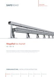
<strong>Limes</strong> Mobil3<strong>Limes</strong> <strong>Product</strong> <strong>Family</strong>Innovative Temporary Safety Barriers<strong>Limes</strong> Mobil3making mobility safer
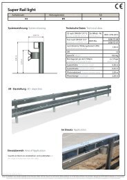
2<strong>Limes</strong> Mobil <strong>Product</strong> <strong>Family</strong>Mobile safety barriers
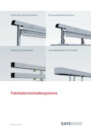
6<strong>Limes</strong> Mobil <strong>Product</strong> <strong>Family</strong><strong>Limes</strong> TS<strong>Limes</strong> TSApplications Areas• between worksite and parallel flowing traffic (application area B)• between opposing traffic flows (application area D)Due to the low width relevant to planning, the system may be usedon an especially narrow temporary lane and is ready for assembly anddisassembly in the shortest period of time. The element lengths of4 m, 8 m or 12 m permit a flexible use of the system.© <strong>Limes</strong> Mobil <strong>GmbH</strong>, as of 2012
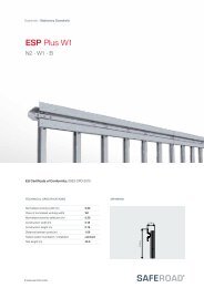
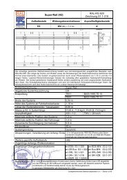
<strong>Limes</strong> Mobil <strong>Product</strong> <strong>Family</strong><strong>Limes</strong> TS 7<strong>Limes</strong>3TST1 · W3 · A / T3 · W5 · ATested in accordance with DIN EN 1317TüV-№: X69.03.D01, X69.05.D02BASt-№: 2006 7S 72/RK, 2005 7S 59/MWTECHNICAL DATADRAWINGWeight per metreConstruction length per day / 3 menElements per truckSystem heightSystem widthPlanning relevant widthLength of a single element30.0 kg1.8 km720 m0.50 m0.45 m0.45 m12.0 m© <strong>Limes</strong> Mobil <strong>GmbH</strong>, as of 2012
<strong>Limes</strong> Mobil <strong>Product</strong> <strong>Family</strong><strong>Limes</strong> TS 9Special constructionsTurn-tilt-elementThe turn-tilt element of <strong>Limes</strong> TS consists of four joint members,which are connected with one another through joint axes insuch a manner that the opposite joint members can be twistedagainst one another. The turn-tilt element is designed in such away that the longitudinal forces in the barrier are conducted viathe joint axes and their bolts, whereas the torsion stress is interrupted.Due to the conic box profiles, the assembly can only beconducted in one direction (in line with the system’s orientation).Application area: To prevent a domino effect of a rear-end collision,there is the possibility of mounting a turn-tilt element.The recommendation is for every 240 m.© <strong>Limes</strong> Mobil <strong>GmbH</strong>, as of 2012
10<strong>Limes</strong> Mobil <strong>Product</strong> <strong>Family</strong><strong>Limes</strong> TSSpecial constructionsDilatation jointsThe dilatation elements are designed to offer the necessary longitudinalcompensation in case of temperature swings, vibrationson bridges or repairs following possible accident damage.Dilatation elements that are to be fitted into the barrier systemas a special structure are used for this purpose. For the dilatationjoints, + 10°C are regarded as zero level, in which case the longholes overlap exactly.The bolts of the dilatation joints may only be tightened to sucha degree that they do not hamper the longitudinal movement.The bolts are to be locked professionally with a locknut (minimumtorque approx. 70 Nm)Application areas: Assembly is recommended for every 240 m.© <strong>Limes</strong> Mobil <strong>GmbH</strong>, as of 2012
<strong>Limes</strong> Mobil <strong>Product</strong> <strong>Family</strong><strong>Limes</strong> TS 11Special constructionsTurn-tilt-element with dilatationApart from the short lowering (see above), one can also mounta long lowering with bolts. The assembly as well as the functioncorresponds with the short lowering.Application area: To prevent a domino effect of a rear-end collision,there is the possibility of mounting a turn-tilt element.The recommendation is for every 240 m.© <strong>Limes</strong> Mobil <strong>GmbH</strong>, as of 2012
12<strong>Limes</strong> Mobil <strong>Product</strong> <strong>Family</strong><strong>Limes</strong> T3<strong>Limes</strong> T3Application area• between worksite and oncoming traffic (application area A)• between worksite and parallel flowing traffic (application area B)• between opposing traffic flows (application area D)• between opposing traffic flows in crossover areas (application area E)Due to the low width relevant to planning, the system may be used incase of minimal carriageway widths. The structural height permits anoptimal connection with a stationary safety barrier system.© <strong>Limes</strong> Mobil <strong>GmbH</strong>, as of 2012
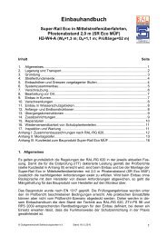
<strong>Limes</strong> Mobil <strong>Product</strong> <strong>Family</strong><strong>Limes</strong> T313<strong>Limes</strong>3T3T1 · W2 · A / T3 · W4 · A / H2 · W8 · BTested in accordance with DIN EN 1317TüV-№: X69.01.D01, X69.02.D01BASt-№: 2005 7S 58/MWTECHNICAL DATADRAWINGWeight per metreConstruction length per day / 3 menElements per truckSystem heightSystem widthPlanning relevant widthLength of a single element88.0 kg1.5 km180 m0.75 m0.50 m0.30 m12.0 m© <strong>Limes</strong> Mobil <strong>GmbH</strong>, as of 2012
14<strong>Limes</strong> Mobil <strong>Product</strong> <strong>Family</strong><strong>Limes</strong> T3TerminalsLowering shortLowerings may be used at the beginning and end of the safetybarrier, which are formed in such a way that an oncoming vehicleis deflected. The assembly is conducted using a claw couplingas a plug-in system without bolting. If the lowering is tobe anchored, this can be accomplished using Sigma posts.Lowering auxiliaryThe longer auxiliary lowering represents an alternative to thestandardised lowering element, consisting of a lowered safetybarrier and a short lowering.The auxiliary lowering is fastened to the end of the barrier bymeans of a plug-in system.© <strong>Limes</strong> Mobil <strong>GmbH</strong>, as of 2012
<strong>Limes</strong> Mobil <strong>Product</strong> <strong>Family</strong><strong>Limes</strong> T315Special constructionsDilatation jointsThe dilatation elements are designed to offer the necessary longitudinalcompensation in case of temperature swings, vibrationson bridges or repairs following possible accident damage.Dilatation elements that are to be fitted into the barrier systemas a special structure (also plug-in system) are used for this purpose.For the dilatation joints, + 10°C are regarded as zero level,in which case the long holes overlap exactly.The bolts of the dilatation joints may only be tightened to sucha degree that they do not hamper the longitudinal movement.The bolts are to be locked professionally with a locknut (minimumtorque approx. 70 Nm).Application area: Assembly is recommended for every 240 m.© <strong>Limes</strong> Mobil <strong>GmbH</strong>, as of 2012
16<strong>Limes</strong> Mobil <strong>Product</strong> <strong>Family</strong><strong>Limes</strong> Berlin<strong>Limes</strong> BerlinApplication area• between worksite and parallel flowing traffic (application area B)• between opposing traffic flows (application area D)Due to the element lengths of 4 m, 8 m or 12 m, a flexible and varieduse of the system is possible in narrow carriageways.© <strong>Limes</strong> Mobil <strong>GmbH</strong>, as of 2012
<strong>Limes</strong> Mobil <strong>Product</strong> <strong>Family</strong><strong>Limes</strong> Berlin17<strong>Limes</strong>3BerlinT1 · W3 · A / T3 · W6 · ATested in accordance with DIN EN 1317BASt-№: 98 7 S 15/LU, 98 7 S 16/LUTECHNICAL DATADRAWINGWeight per metre57.0 kgConstruction length per day / 3 men 1.6 km * / 1.1 km **Elements per truckSystem heightSystem widthPlanning relevant widthLength of a single element204 m0.65 m0.50 m0.50 m12.0 m*Assembly with connection support**Assembly without connection support with 5 men© <strong>Limes</strong> Mobil <strong>GmbH</strong>, as of 2012
18<strong>Limes</strong> Mobil <strong>Product</strong> <strong>Family</strong><strong>Limes</strong> BerlinTerminalsLowering short with connection supportLowerings may be used at the beginning and end of the safetybarrier, which are formed in such a way that an oncoming vehiclewill be deflected to one side and not butt into the end of thebarrier. There is the possibility of anchoring the lowering withSigma posts. In order to accomplish this, the Sigma posts arerammed into the respective holes in the ground.Lowering long with connection supportThe standardised lowering of <strong>Limes</strong> Berlin comes in a short version(see above) and in a long version with connection support.Both lowerings are double tapered and end with a vertical step.The lowerings are rounded off and inclined laterally, so that asliding of the vehicle tyre is guaranteed.© <strong>Limes</strong> Mobil <strong>GmbH</strong>, as of 2012
<strong>Limes</strong> Mobil <strong>Product</strong> <strong>Family</strong><strong>Limes</strong> Berlin19TerminalsLowering short without connection supportA long lowering without a connection support represents anotherlowering alternative. The so-called regular lowering isused when the system is not fitted with connection supports.The assembly is conducted by bolting the lowering element tothe barrier end.Reversing terminalsThe return terminals may also form the end of the steel safetybarriers. The return terminals are inclined vertically and horizontallyand enclose the barrier end either at the top or the bottomrespectively.© <strong>Limes</strong> Mobil <strong>GmbH</strong>, as of 2012
20<strong>Limes</strong> Mobil <strong>Product</strong> <strong>Family</strong><strong>Limes</strong> BerlinSpecial constructionsTurn-tilt-elementA complete joint consists of two joint members that are connectedwith one another through a horizontal shaft (joint axis)in such a manner that the two joint members can be twistedagainst one another. The connection with the protective barrieris conducted by means of connection supports. The joint membersare designed in such a way that the longitudinal forces inthe barrier are passed on via the shaft and its bolts, whereas thetorsion stress is interrupted.Application area: It is recommended in case of longer stretchesthat run primarily straight to mount a joint approx. every 240 m.In curves, the tilt inclination of the barrier is lower, so that thespace between the joints may be 400 m to 600 m.© <strong>Limes</strong> Mobil <strong>GmbH</strong>, as of 2012
<strong>Limes</strong> Mobil <strong>Product</strong> <strong>Family</strong><strong>Limes</strong> Berlin21Special constructionsDilatation jointsThe dilatation elements are designed to offer the necessary longitudinalcompensation in case of temperature swings, vibrationson bridges or repairs following possible accident damage.For this purpose, dilatation elements are used as they are stipulatedfor stationary safety barrier systems by the TL-SP.For the dilatation joints, + 10°C are regarded as zero level, inwhich case the long holes overlap exactly. The bolts of the dilatationjoints may only be tightened to such a degree that theydo not hamper the longitudinal movement.The bolts are to be locked professionally with a locknut (minimumtorque approx. 70 Nm). The dilatation elements are to bepositioned according to the cross-section of the barrier (in all 4elements).Application area: The standard element is the 320-dilatation.The assembly is recommended for every 240 m.© <strong>Limes</strong> Mobil <strong>GmbH</strong>, as of 2012
22<strong>Limes</strong> Mobil <strong>Product</strong> <strong>Family</strong>ProTec 120ProTec 120Application area• between worksite and oncoming traffic (application area A)• between worksite and parallel flowing traffic (application area B)• between opposing traffic flows (application area D)• between opposing traffic flows in crossover areas (application area E)The mobile safety barrier system ProTec 120 combines the flexibility ofsteel with the stability of concrete.© <strong>Limes</strong> Mobil <strong>GmbH</strong>, as of 2012
<strong>Limes</strong> Mobil <strong>Product</strong> <strong>Family</strong>ProTec 12023ProTec 120T1 · W1 · A / T3 · W2 · A / H1 · W5 · ATested in accordance with DIN EN 1317TüV-№: X82.03.H06, X82.04.H06, X82.07.H09, X82.08.H09BASt-№: 2007 7E 57, 2008 7E 54TECHNICAL DATADRAWINGWeight per metreConstruction length per day / 3 menElements per truckSystem heightSystem widthPlanning relevant widthLength of a single element163.0 kg1.2 km140 m0.60 m0.30 m0.12 m10.0 m© <strong>Limes</strong> Mobil <strong>GmbH</strong>, as of 2012
24<strong>Limes</strong> Mobil <strong>Product</strong> <strong>Family</strong>ProTec 120TerminalsLoweringLowerings may be used at the beginning and end of the steelsafety barrier, which are formed in such a way that an oncomingvehicle will be deflected to one side and not butt into the endof the barrier. The ProTec 120 lowering is mounted to the safetybarrier with posts, just like all the other elements.© <strong>Limes</strong> Mobil <strong>GmbH</strong>, as of 2012
<strong>Limes</strong> Mobil <strong>Product</strong> <strong>Family</strong>ProTec 12025Special constructionsDilatation jointsThe dilatation elements are designed to offer the necessarylongitudinal compensation in case of temperatureswings, vibrations on bridges or repairs following possibleaccident damage. When mounting the dilatationelements, it is essential that the fastening of the slidingunits is always positioned in the centre, so that the elementmay expand.Application area: As a rule, the elements should bemounted on bridges on the level of the expansion jointof the bridge and fitted every 500 m along mountedstretches as of 1.000 m.© <strong>Limes</strong> Mobil <strong>GmbH</strong>, as of 2012
26<strong>Limes</strong> Mobil <strong>Product</strong> <strong>Family</strong>TransitionsTransitions© <strong>Limes</strong> Mobil <strong>GmbH</strong>, as of 2012
<strong>Limes</strong> Mobil <strong>Product</strong> <strong>Family</strong>Transitions27<strong>Limes</strong> T3 – <strong>Limes</strong> TSThe safety barrier <strong>Limes</strong> T3 may be connected to the safety barrier <strong>Limes</strong> TS with a transition element. There are no additional componentsrequired for the transition element, which makes for a simple assembly.<strong>Limes</strong> Berlin – <strong>Limes</strong> TSThe safety barrier <strong>Limes</strong> Berlin may be connected to the safety barrier <strong>Limes</strong> TS with a transition element. There are no additional componentsrequired for the transition element, which makes for a simple assembly.© <strong>Limes</strong> Mobil <strong>GmbH</strong>, as of 2012
28<strong>Limes</strong> Mobil <strong>Product</strong> <strong>Family</strong>Transitions<strong>Limes</strong> T3 – <strong>Limes</strong> BerlinThe safety barrier <strong>Limes</strong> Berlin may be connected to the safety barrier <strong>Limes</strong> T3 with a transition element. There are no additional componentsrequired for the transition element, which makes for a simple assembly.ProTec 120 – <strong>Limes</strong> BerlinThe safety barrier <strong>Limes</strong> Berlin may be connected to ProTec 120 with a transition element. There are no additional components requiredfor the transition element, which makes for a simple assembly.© <strong>Limes</strong> Mobil <strong>GmbH</strong>, as of 2012
<strong>Limes</strong> Mobil <strong>Product</strong> <strong>Family</strong>Transitions29ProTec 120 – <strong>Limes</strong> T3The safety barrier <strong>Limes</strong> T3 may be connected to ProTec 120 with a transition element. There are no additional components required forthe transition element, which makes for a simple assembly.ProTec 120 – <strong>Limes</strong> TSThe safety barrier <strong>Limes</strong> TS may be connected to ProTec 120 with a transition element. There are no additional components required forthe transition element, which makes for a simple assembly.© <strong>Limes</strong> Mobil <strong>GmbH</strong>, as of 2012
30<strong>Limes</strong> Mobil <strong>Product</strong> <strong>Family</strong>Transitions<strong>Limes</strong> TS – Stationary systemsThe safety barrier <strong>Limes</strong> TS may be connected to stationary safety barrier systems with a transition element. Whereby the end of thelower box profile band is formed by assembling a return terminal.<strong>Limes</strong> Berlin – Stationary systemsThe safety barrier <strong>Limes</strong> Berlin may be connected to stationary safety barrier systems with a transition element. Whereby the end of thebarrier is formed by assembling a return terminal.© <strong>Limes</strong> Mobil <strong>GmbH</strong>, as of 2012
<strong>Limes</strong> Mobil <strong>Product</strong> <strong>Family</strong>Transitions31ProTec 120 – Stationary systemsThe safety barrier ProTec 120 may be connected to stationary safety barrier systems with a transition element.<strong>Limes</strong> TS – ConcreteThe safety barrier <strong>Limes</strong> TS may be connected to concrete safety barrier systems with a transition element.© <strong>Limes</strong> Mobil <strong>GmbH</strong>, as of 2012
<strong>Limes</strong> Mobil <strong>GmbH</strong>Landshuter Straße 110779 BerlinGERMANYAußenstelle DorstenBaddenkamp 2146286 DorstenGERMANYT: + 49 30 21 47 83 38F: + 49 30 21 47 83 37berlin@limes-mobil.dewww.limes-mobil.deT: +49 2369 20 95 260F: +49 2369 20 95 261dorsten@limes-mobil.dewww.limes-mobil.de