Installation Instruction
Installation Instruction
Installation Instruction

Create successful ePaper yourself
Turn your PDF publications into a flip-book with our unique Google optimized e-Paper software.
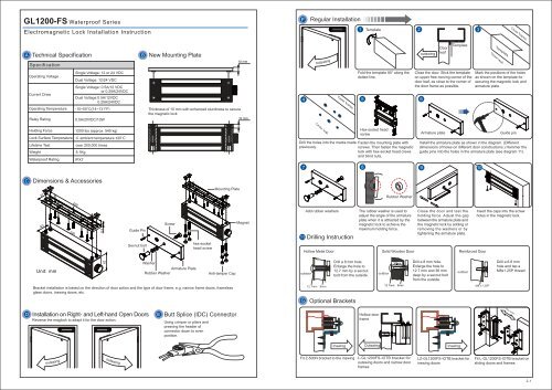
GL1200-FSWaterproof SeriesRegular <strong>Installation</strong>Electromagnetic Lock <strong>Installation</strong> <strong>Instruction</strong>TemplateDoor frameTechnical SpecificationSpecificationNew Mounting PlateoutswingoutswingDoorleafTemplateTemplateDoor leafOperating VoltageCurrent DrawSingle Voltage: 12 or 24 VDCDual Voltage: 12/24 VDCSingle Voltage: 0.5A/12 VDCor 0.25A/24VDCDual Voltage:0.5A/12VDC0.25A/24VDCFold the template 90° along thedotted line.Close the door. Stick the templateon upper free-moving corner of thedoor leaf, as close to the corner ofthe door frame as possible.Mark the positions of the holesas shown on the template forsecuring the magnetic lock andarmature plate.Door frameOperating TemperatureRelay Rating-10~55°C(14~131°F)0.5A/20VDC/10WThickness of 10 mm with enhanced sturdiness to securethe magnetic lockHolding ForceLock Surface TemperatureLifetime TestWeightWaterproof Rating1200 lbs (approx. 545 kg) ambient temperature ±20˚Cover 200,000 times5.1KgIPX7Door leafDrill the holes into the marks made Fasten the mounting plate withpreviously.screws. Then fasten the magneticlock with hex-socket head crewsand blind nuts.Hex-socket headscrew Armature plate Guide pinInstall the armature plate as shown in the diagram. (Differentdimensions of holes on different door constructions.) Hammer theguide pins into the holes in the armature plate (see diagram 11).Dimensions & AccessoriesMounting PlateRubber Washer40Guide PinSexnut boltScrewhex-sockethead screwMagnetAdd rubber washersDrilling <strong>Instruction</strong>Hollow Metal DoorThe rubber washer is used toadjust the angle of the armatureplate when it is attracted by themagnetic lock to achieve themaximum holding force.Solid Wooden DoorClose the door and test theholding force. Adjust the gapbetween the armature plate andthe magnetic lock by adding orremoving the washers or bytightening the armature plate.Reinforced DoorInsert the caps into the screwholes in the magnetic lock.62WasherArmature PlateRubber WasherAnti-tamper CapoutdoorDrill a 8 mm hole.Enlarge the hole to12.7 mm by a sexnutbolt from the outside.outdoorDrill a 8 mm hole.Enlarge the hole to12.7 mm and 36 mmdeep by a sexnut boltfrom the outside.outdoorDrill a 6.8 mmhole and tap aM8x1.25P thread.Bracket installation is based on the direction of door action and the type of door frame, e.g. narrow frame doors, framelessglass doors, inswing doors, etc.12.7mm8mmM8 x1.25PGOptional Brackets<strong>Installation</strong> on Right- and Left-hand Open DoorsReverse the maglock to adapt it for the door action.Butt Splice (IDC) ConnectorUsing crimper or pliers andpressing the header ofconnector down to evenposition.Hollow doorframeDoor actionInswingOutswingInswingoutswingoutswingFit Z-500N bracket to the inswingL-GL1200FS-IOTB bracket foroutswing doors and narrow doorframesLZ-GL1200FS-IOTB bracket forinswing doorsFit L-GL1200FS-IOTB bracket onsliding doors and frames.
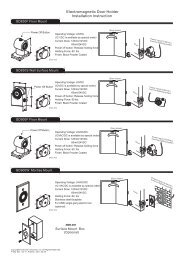
LZ bracket for inswing doors (Surface Mount)KConnecting Diagramwith 2 m cablesDoor frameModelWire Leads(Power input is polarity free)Power InputBond sensoroutputDiagramInstall the L bracket to themounting position on thedoor frame. Make sure thedoor can be freely opened.Fasten the magnetic lock tothe L bracket with hex-sockethead screws.Assemble the Z bracket. Notethat the bracket is movable.Insert the guide pins into thearmature plate.GL1200-FS-IOTB-12GL1200-FS-IOTB-242 Wire LeadsControl DeviceN.C contact or Access RelayRedBlackPowerSupplyPowerPowerFasten armature plate to Zbracket. The rubber washermust be placed between thearmature plate and the bracket.Close the door and connectto the power.Z bracket for inswing doors (Face Mount)OutdoorAfter the armature plate andthe magnetic lock stick to eachother, adjust the Z bracket to fitthe door frame.OutdoorAdjust and fasten the Z bracket.Close the door and test theholding force. Adjust the gapbetween the armature plate andthe magnetic lock by adding orremoving the washers or bytightening the armature plate.GL1200M-FS-IOTB-12GL1200M-FS-IOTB-245 Wire LeadsControl DeviceN.C contact or Access RelayBlueBlueVoltage Selection:12VDCPowerSupplyWhite N.C.Black COM.Red N.O.Voltage Selection:24VDCtemplate4GL1200-FS-IOTB4 Wire LeadsRedWhiteBlackGreenPowerSupplyRedWhiteBlackGreenPowerSupplyControl DeviceN.C contact or Access RelayControl DeviceN.C contact or Access RelayDrill holes as shown ontemplate and fit blind nutsinto holes. Fit maglocks withhex-socket head screws.Insert caps into screw holesin maglock.5 67Assemble Z bracket. Notethat the bracket is movable.powerInsert guide pins intoarmature plate (to fix it).8powerGL1200R-FS-IOTB6 Wire LeadsVoltage Selection:12VDCRedWhiteBlackGreenPowerSupplyControl DeciveN.C. contact Access RelayBlue COM.Yllow N.O.Voltage Selection:24VDCRedWhiteBlackGreenPowerSupplyControl DeciveN.C. contact Access RelayBlue COM.Yllow N.O.Voltage Selection:12VDCVoltage Selection:24VDCFasten armature plate toZ bracket. Add plasticwashers between bracketand armature plate.Note:Close door and connectto the power.Power SupplyoutdoorAfter maglock attractsarmature plate, fit Zbracket to door leaf.Control DeviceoutdoorAdjust and fasten upper partof Z bracket. Close door andtest holding force. Adjust thegap between armature plateand maglocks by adding orremoving washers or tighteningthe armature plate.LGL1200M-FS-IOTBTrouble Shooting7 Wire LeadsRedWhiteBlackGreenPowerSupplyControl DeciveN.C. contact Access RelayBrown N.C.Blue COM.Yllow N.O.RedWhiteBlackGreenPowerSupplyControl DeciveN.C. contact Access RelayBrown N.C.Blue COM.Yllow N.O.ProblemPossible CauseSolutionThe magnetic lock must face-tofacealign with the armature plateor the holding force will decreaseby 25%.Regularly wipe the surfaceof the magnetic lock withanti-rust oil.Do not apply power wiresand signal wires in the samecable or conduit.InswingThe magnetic lock and wiresmust not be exposed. InstallLZ bracket for inswingdoors.The magnetic lock is fail-safe.It requires a UPS to supplypower to keep the doorlocked during power failure.Make sure the faces of themagnetic lock and the armatureplate are clean, intact and norust.Remove any diode andvaristor to prevent the doorfrom delayed opening.Door doesnot lockLow holdingforceSensor outputis notfunctioningNo powerPoor contact between electromagnetand armature plateLow voltage or incorrect voltagesettingA secondary diode was installedacross the electromagnet lockMisalignment between the armatureplate and electromagnet lock1. Make sure the wires are properly connected.2. Make sure the power supply unit works well.3. Make sure the relay is connected to the N.C. contact.1. See if the armature plate is deformed.2. Make sure to insert the rubber washer between the armature plate and the bracket.3. See if the surfaces of the armature plate and the magnetic lock are clean.1. Check if the voltage selection is correct.2. Check the power voltage at the terminals.Remove any diode installed across the magnetic lock.Make sure the armature plate and the magnetic lock are aligned face-to-face.HCopyright © 2011 All Rights Reserved. P-MU-WP-GL1200-FS Ver. A Publish: 2011.07.27