OFDM(A) for wireless communication - Unik
OFDM(A) for wireless communication - Unik
OFDM(A) for wireless communication - Unik

You also want an ePaper? Increase the reach of your titles
YUMPU automatically turns print PDFs into web optimized ePapers that Google loves.
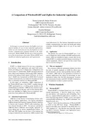
<strong>OFDM</strong>(A) <strong>for</strong> <strong>wireless</strong> <strong>communication</strong>R&I Research Report R 7/2008Title<strong>OFDM</strong>(A) <strong>for</strong> <strong>wireless</strong> <strong>communication</strong>Author(s)Per Hjalmar Lehne, Frode BøhagenISBN / ISSN 82-423-0614-1 / 1500-2616Security groupOPENDate 2008.04.25AbstractThis report is a tutorial on Orthogonal Frequency Division Multiplex (<strong>OFDM</strong>) andOrthogonal Frequency Division Multiple Access (<strong>OFDM</strong>A). <strong>OFDM</strong>A is the majortransmission and access technology <strong>for</strong> future mobile broadband systems like MobileWiMAX and 3GPP Long Term Evolution (LTE).One of the key features of <strong>OFDM</strong> and <strong>OFDM</strong>A is the ability to handle multipathpropagation without complex receivers. The use of simple and cost-efficient Fast FourierTrans<strong>for</strong>m (FFT) techniques makes it easily scalable with respect to bandwidth. Themain drawback is that the signal has high amplitude variability, high so-called Peak-to-Average-Power Ratio (PAPR), which typically reduces the efficiency of the transmitterpower amplifiers. The two major standards <strong>for</strong> mobile broadband, namely Mobile WiMAXand 3GPP LTE are very similar in the design targets and the solutions are comparable.From a technical and per<strong>for</strong>mance point of view they seem to be quite equal.Radio planning of <strong>OFDM</strong>A networks is more equal to GSM planning than WCDMA,because intra-cell interference is basically eliminated due to the orthogonality property.Scalable <strong>OFDM</strong>A opens up new ideas on frequency reuse, in that the reuse factor can bebetween 1 and 3 (or more) on a fractional basis. Furthermore, different cell capacitiescan be tuned cooperatively, e.g. by moving capacity from one cell to another dependenton time of day.Keywords<strong>OFDM</strong>, <strong>OFDM</strong>A, Wireless, Mobile, 4G, WiMAX, E-UTRA, LTETelenor R&I R 7/2008
<strong>OFDM</strong>(A) <strong>for</strong> <strong>wireless</strong> <strong>communication</strong>© Telenor ASA 2008.04.25All rights reserved. No part of this publication may be reproduced or utilized inany <strong>for</strong>m or by any means, electronic or mechanical, including photocopying,recording, or by any in<strong>for</strong>mation storage and retrieval system, withoutpermission in writing from the publisher.Telenor R&I R 7/2008
<strong>OFDM</strong>(A) <strong>for</strong> <strong>wireless</strong> <strong>communication</strong>PrefaceThis report is the result of a technology study per<strong>for</strong>med in 2007. The aim ofthe study has been to develop the competence in Telenor R&I on the multipleaccess scheme <strong>OFDM</strong>A. <strong>OFDM</strong>A is the transmission and access technology to beused in future mobile broadband systems like Mobile WiMAX and 3GPP LongTerm Evolution.The study was finalized with an internal workshop arranged on 23 January2008.Telenor R&I R 7/2008
<strong>OFDM</strong>(A) <strong>for</strong> <strong>wireless</strong> <strong>communication</strong>Contents1 Introduction.......................................................... 12 Introduction to <strong>OFDM</strong> ........................................... 22.1 <strong>OFDM</strong> basic concept ................................................................. 32.1.1 Orthogonality principle ............................................................. 42.1.2 Instantaneous power variations ................................................. 72.1.3 Wireless channel influence ...................................................... 102.1.4 Signal detection and demodulation........................................... 132.2 Choosing the <strong>OFDM</strong> parameters............................................... 132.2.1 Sub-carrier spacing and symbol time ........................................ 142.2.2 Number of sub-carriers........................................................... 152.2.3 Cyclic prefix length ................................................................ 152.2.4 Pulse shaping and windowing functions..................................... 163 Multi-user <strong>communication</strong>s – <strong>OFDM</strong>A.................. 183.1 Sub-carrier allocation techniques ............................................. 183.1.1 Consecutive (localized) frequency mapping ............................... 183.1.2 Distributed frequency mapping ................................................ 193.1.3 Channel dependent scheduling ................................................ 203.2 Synchronization aspects ......................................................... 203.3 DFT-spread <strong>OFDM</strong>A (SC-FDMA) ............................................... 214 Wireless standards based on <strong>OFDM</strong>(A) ............... 244.1 3GPP Evolved UTRA (Long Term Evolution)................................ 244.1.1 Radio resource definitions ....................................................... 254.1.2 Modulation and coding............................................................ 284.1.3 Multi-antenna support ............................................................ 284.1.4 Downlink scheduling and reference signals ................................ 294.1.5 Uplink scheduling and reference signals .................................... 304.2 Mobile WiMAX ....................................................................... 314.2.1 Radio resource definitions – sub-channelization.......................... 324.2.2 Diversity permutations ........................................................... 334.2.3 Contiguous permutation ......................................................... 364.2.4 Permutation schemes summary ............................................... 374.2.5 Modulation and coding............................................................ 374.2.6 Multi-antenna support ............................................................ 384.2.7 Frame Structure .................................................................... 384.3 E-UTRA vs. Mobile WiMAX – summary ...................................... 404.4 Other <strong>OFDM</strong> and <strong>OFDM</strong>A based standards ................................. 414.4.1 Mobile WiMAX Release 2 – IEEE 802.16m.................................. 414.4.2 3GPP2 Ultra Mobile Broadband (UMB) ....................................... 414.4.3 Wi-Fi and WLAN 802.11a-g-n .................................................. 424.4.4 WPAN 802.15.3a Multi Band <strong>OFDM</strong>........................................... 424.4.5 Digital terrestrial video broadcast – DVB-T/H ............................. 435 <strong>OFDM</strong>A radio planning......................................... 445.1 Frequency reuse.................................................................... 455.1.1 Frequency reuse 1 ................................................................. 465.1.2 Frequency reuse 3 ................................................................. 46Telenor R&I R 7/2008
<strong>OFDM</strong>(A) <strong>for</strong> <strong>wireless</strong> <strong>communication</strong>5.1.3 Fractional frequency reuse ...................................................... 475.2 <strong>OFDM</strong>A link budgets ............................................................... 486 Conclusions .........................................................50References ..................................................................52Annex 1. Abbreviations ...............................................54Telenor R&I R 7/2008
<strong>OFDM</strong>(A) <strong>for</strong> <strong>wireless</strong> <strong>communication</strong>1 IntroductionOrthogonal Frequency Division Multiplex (<strong>OFDM</strong>) is a multi carrier transmissiontechnology which was first described by R. W. Chang in 1966 at Bell Labs. Thefirst patent was granted in 1970 (US patent 3488445). Later, M. Fattouche andH. Zaghloul described how the <strong>OFDM</strong> concept can be used to provide multipleaccess between different transceivers (US patent 5282222, granted in 1994).This was the first description of Orthogonal Frequency Division Multiple Access(<strong>OFDM</strong>A).The first <strong>OFDM</strong> based <strong>wireless</strong> standard was probably the Eureka Digital AudioBroadcast (DAB) standard <strong>for</strong> audio broadcasting which was released in 1995.Two years later, in 1997, the standard <strong>for</strong> terrestrial digital television, i.e. DVB-T, was published.<strong>OFDM</strong> and <strong>OFDM</strong>A is now becoming the major transmission and accesstechnology <strong>for</strong> future mobile broadband systems. Mobile WiMAX is alreadyavailable, and 3GPP has left WCDMA in favour of <strong>OFDM</strong>A <strong>for</strong> the next generationstandard Evolved UTRA, often referred to as Long Term Evolution (LTE).This report is a tutorial on <strong>OFDM</strong> and <strong>OFDM</strong>A, and is organized in four chapters.First, in Chapter 2 we introduce <strong>OFDM</strong> transmission, and define and discuss allmajor parameters. In Chapter 3 we explain how the <strong>OFDM</strong> concept can beaugmented to comprise multiple access as <strong>OFDM</strong>A. Chapter 4 deals with themajor standards using <strong>OFDM</strong>A. The weight has been put on Mobile WiMAX and3GPP E-UTRA, but a brief description of other <strong>OFDM</strong>(A) based standards is alsoincluded. Finally, in Chapter 5 radio planning <strong>for</strong> an <strong>OFDM</strong>A network isdiscussed and compared with current knowledge from 2G (GSM) and 3G(WCDMA) planning. Some examples of link budget calculations are alsopresented.Telenor R&I R 7/2008 - 1
<strong>OFDM</strong>(A) <strong>for</strong> <strong>wireless</strong> <strong>communication</strong>2 Introduction to <strong>OFDM</strong>Orthogonal Frequency Division Multiplexing (<strong>OFDM</strong>) is a multi-carriermodulation scheme that transmits data over a number of orthogonal subcarriers.A conventional transmission uses only a single carrier modulated withall the data to be sent. <strong>OFDM</strong> breaks the data to be sent into small chunks,allocating each sub-data stream to a sub-carrier and the data is sent in parallelorthogonal sub-carriers. As illustrated in Figure 1, this can be compared with atransport company utilizing several smaller trucks (multi-carrier) instead of onelarge truck (single carrier).Single CarrierMulti CarrierFigure 1 Single carrier vs. multi-carrier transmission<strong>OFDM</strong> is actually a special case of Frequency Division Multiplexing (FDM). Ingeneral, <strong>for</strong> FDM, there is no special relationship between the carrierfrequencies, f 1 , f 2 and f 3 . Guard bands have to be inserted to avoid AdjacentChannel Interference (ACI). For <strong>OFDM</strong> on the other hand, there must be a strictrelation between the frequency of the sub-carriers, i.e. f n = f 1 + n⋅Δf where Δf =1/T U and T U is the symbol time. Carriers are orthogonal to each other and canbe packed tight as shown in Figure 2.2 - Telenor R&I R 7/2008
<strong>OFDM</strong>(A) <strong>for</strong> <strong>wireless</strong> <strong>communication</strong>ChannelbandwidthGuard bandIndividual channelsFDMf 1f 2f 3f 1f 2f 3ChannelbandwidthIndividual sub-channelsFrequency<strong>OFDM</strong>BandwidthsavingBandwidthsavingFrequencyFigure 2 FDM vs. <strong>OFDM</strong>Splitting the channel into narrowband channels enables significant simplificationof equalizer design in multipath environments. Flexible bandwidths are enabledthrough scalable number of sub-carriers.Effective implementation is further possible by applying the Fast FourierTrans<strong>for</strong>m (FFT). Dividing the channel into parallel narrowband sub-channelsmakes coding over the frequency band possible (C<strong>OFDM</strong>). Moreover, it ispossible to exploit both time and frequency domain variations, i.e. time andfrequency domain adaptation.2.1 <strong>OFDM</strong> basic conceptA baseband <strong>OFDM</strong> transmission model is shown in Figure 3. It basically consistsof a transmitter (modulator, multiplexer and transmitter), the <strong>wireless</strong> channel,and a receiver (demodulator).Telenor R&I R 7/2008 - 3
<strong>OFDM</strong>(A) <strong>for</strong> <strong>wireless</strong> <strong>communication</strong>channelFigure 3 Basic baseband <strong>OFDM</strong> transmission modelIn Figure 3, a bank of modulators and correlators is used to describe the basicprinciples of <strong>OFDM</strong> modulation and demodulation. This is not practicallyfeasible, and the specific choice of sub-carrier spacing being equal to the percarrier symbol rate 1/T U makes a simple and low complexity implementationusing Fast Fourier Trans<strong>for</strong>m (FFT) processing possible as shown in Figure 4.For more details on the FFT implementation we refer to [Nee00].channelFigure 4 Transmitter and receiver by using FFT processingIn the consecutive subsections we will discuss the most important properties ofthe <strong>OFDM</strong> transmitter (Section 2.1.1), <strong>OFDM</strong> signal properties (Section 2.1.2),the <strong>OFDM</strong> channel (Section 2.1.3), and the <strong>OFDM</strong> receiver (Section 2.1.4)2.1.1 Orthogonality principleThe essential property of the <strong>OFDM</strong> signal is the orthogonality between the subcarriers.Orthogonal means “perpendicular”, or at “right angle”.Two functions, x q (t) and x k (t), are orthogonal over an interval [a, b] if the innerproduct between them is zero <strong>for</strong> all q and k, except <strong>for</strong> the case that q = k, i.e.when x q (t) and x k (t) are the same function. Mathematically this can be writtenas:b U⎧1,k = qxq, xk=∫xq( t)⋅ xk( t)dt = ⎨(1)⎩0,k ≠ qa4 - Telenor R&I R 7/2008
<strong>OFDM</strong>(A) <strong>for</strong> <strong>wireless</strong> <strong>communication</strong>If we look at receiver branch k in Figure 3, the output of the integrator can beexpressed as follows:1T=TU TU NC−1− j2πkΔft1∫r(t)⋅ e dt =∫ ∑ aqUT0U0 q=0N −1C∑q=0aTTUqU∫0ej2π( q−k)1tTU⎛⎜⎜⎝⎧ak,dt = ⎨⎩0 ,⋅ ek = qk ≠ qj2πqΔft⎞⎟ ⋅ e⎟⎠− j2πkΔftdt(2)In this example we assume no noise or multipath degradation of the signal(ideal channel). We see that the last integral satisfies the orthogonalitydefinition. Consequently, the harmonic exponential functions (sine wavecarriers) with frequency separation Δf = 1/T U are orthogonal.This property gives optimum spectrum utilization and makes it possible toseparate the sub-carriers in the receiver. Figure 5 is an attempt to illustratehow the orthogonality works in the time domain, if e.g. x q is the received subcarrier,and x k represents the local oscillator as shown in Figure 3. Whenintegrating received power over one symbol period, T U , the output of thecorrelators is zero <strong>for</strong> any combination, except when k = q.When the sub-carriers are modulated with a rectangular pulse the sub-carrierspectrum becomes as shown in Figure 6. This implies that in the frequencydomain, the power of sub-carriers approaches zero at the centre frequency ofthe neighbouring sub-carriers as shown in Figure 7. The figure shows the powerspectrum of the individual sub-carriers of an <strong>OFDM</strong> spectrum.Telenor R&I R 7/2008 - 5
<strong>OFDM</strong>(A) <strong>for</strong> <strong>wireless</strong> <strong>communication</strong>1.5xq, q=61.5xq . xq*110.50.500-0.5-0.5-1-1-1.50 0.2 0.4 0.6 0.8 1-1.50 0.2 0.4 0.6 0.8 11.5xk, k=71.5xq . xk*110.50.500-0.5-0.5-1-1-1.50 0.2 0.4 0.6 0.8 1-1.50 0.2 0.4 0.6 0.8 1Figure 5 Orthogonality principle in the time domain. Leftmost graphs show theinput signal shapes over one symbol period. The rightmost graphs show theintegrand in the case of equal signal (upper) and orthogonal signal (lower). It iseasily seen that the total area under the curve when q = k is positive, while itsums up to zero over one symbol period when the frequencies are different andspaced 1/T U apartFrequency domainTime domainFigure 6 Time and frequency domain representation of the baseband signal6 - Telenor R&I R 7/2008
<strong>OFDM</strong>(A) <strong>for</strong> <strong>wireless</strong> <strong>communication</strong>Figure 7 Power spectrum of orthogonal sub-carriersA real <strong>OFDM</strong> power spectrum will not look like the one in Figure 7, because apower based measurement cannot distinguish the separate sub-carriers. Figure8 shows a field measurement of a mobile WiMAX spectrum with a bandwidth of5 MHz. The signal consists of 360 active sub-carriers. The FFT-size is 512. Theamplitude variations are due to frequency selective fading caused by multipathtransmissions. This is treated in section 2.1.3.Figure 8 Field measurement of an <strong>OFDM</strong> spectrum (WiMAX) in a LOSenvironment2.1.2 Instantaneous power variationsAn <strong>OFDM</strong> signal consists of a number of independently modulated symbols.Telenor R&I R 7/2008 - 7
<strong>OFDM</strong>(A) <strong>for</strong> <strong>wireless</strong> <strong>communication</strong>Nc∑ − 1kk=0( j2πkΔt )x (t) = a ⋅ ef(3)Adding carriers with different frequencies and modulation gives large amplitudevariations. This is the Peak Power Problem of <strong>OFDM</strong>. It can be shown that themaximum value of the Peak to Average Power Ratio (PAPR) is the same as thenumber of sub-carriers:PAPR =max N C(4)Figure 9 shows a simulated wave<strong>for</strong>m of an <strong>OFDM</strong>-signal with 8 sub-carriersand BPSK modulation. The expanded part of the graph shows that theamplitude variations are large and that the maximum value of the sum can beas high as 8.Figure 9 Amplitude variations in an <strong>OFDM</strong> signal. Example is 8 sub-carriersand BPSK modulationA large PAPR is negative <strong>for</strong> the power amplifier efficiency since a backoff isneeded to avoid amplitude distortion and the following harmonic frequencies.Figure 10 shows a typical input-output characteristic of a power amplifier. Inorder to avoid or limit signal distortion input signals must be kept below thenon-linear area. The consequence is that the amplifier is not fully utilized.8 - Telenor R&I R 7/2008
<strong>OFDM</strong>(A) <strong>for</strong> <strong>wireless</strong> <strong>communication</strong>AM/AM characteristicP OUTOBOIBOAveragePeakP INFigure 10 Typical input-output characteristics of a power amplifier showing therelation between output backoff (OBO) and input backoff (IBO)Different measures to avoid large PAPRs are used and are classified in threemajor techniques:• Signal distortion techniqueso Clipping (signal distortion, out of band radiation, window)ooPeak windowing (reduce the out of band radiation)Peak cancellation (linear, can avoid out of band radiation)• Coding techniqueso Special FEC codes that excludes <strong>OFDM</strong> symbols with a large PAPR(decreasing the desired PAPR this way may decrease achievablecoding gain).oTone reservation is another coding technique where a subset of<strong>OFDM</strong> sub-carriers are not used <strong>for</strong> data transmission but insteadare modulated to suppress the largest peaks of the overall <strong>OFDM</strong>signal.o Pre-filtering or pre-coding, linear processing applied to the <strong>OFDM</strong>symbolsbe<strong>for</strong>e <strong>OFDM</strong> modulation.• Scrambling techniquesoDifferent scrambling sequences are applied, and the one resultingin the smallest PAPR is chosenTelenor R&I R 7/2008 - 9
<strong>OFDM</strong>(A) <strong>for</strong> <strong>wireless</strong> <strong>communication</strong>PAPR reduction techniques applied to different <strong>wireless</strong> standards must partlybe described in the standards, as e.g. coding and scrambling. Signal distortiontechniques however can be a pure implementation aspect, but the use of suchusually means a reduced BER per<strong>for</strong>mance in the receiver.No special technique seems to be specified in WiMAX, but in E-UTRA the uplinktransmission is based on a linear pre-coding technique called DFT-spread<strong>OFDM</strong>, which effectively reduces the PAPR with 2-3 dB [Dahl07] [Myu06b]. Thisis detailed a bit more in section 3.3.2.1.3 Wireless channel influenceA <strong>wireless</strong> channel introduces impairments to the signal, mainly due tomultipath transmission as shown in Figure 11.Diffracted and Refracted Pathα k , τ ][ kLOS Pathα 0 , τ ][ 0α 1 , τ ][ 1Reflected Pathh(t)=K∑ − 1k = 0α δ ( t −τ)kkFigure 11 The multipath channelFigure 12 (left) shows a measured channel impulse response, both the directpath signal and the reflected (echoed) signals. In addition, Figure 12 (right)illustrates a simplification of the impulse response.Amplitude[α]τ τ τ 2Time[τ]Figure 12 Multipath channel impulse response. Left: measured. Right:simplified two ray model10 - Telenor R&I R 7/2008
<strong>OFDM</strong>(A) <strong>for</strong> <strong>wireless</strong> <strong>communication</strong>The consequence of multipath propagation is that time dispersion is introducedin the signal. Figure 13 illustrates the effect in the time domain and how a cyclicprefix (CP) may be used to mitigate the effect. Time-adjacent symbols start tooverlap and inter-symbol-interference (ISI) is introduced (Figure 13a). InFigure 13b the symbol is prolonged by adding a guard time between thesymbols, but just adding an “empty” guard time destroys the orthogonality andintroduces inter-carrier interference (ICI). In order to avoid this and thus tomaintain the orthogonality, the prefix is made cyclic by taking a copy of the lastpart of the symbol and put it in front (Figure 13c). The prefix time must belonger than the longest excess delay which can occur in the channel.a) Multipath introduces inter-symbol-interference (ISI)TT CTb) Prefix is added to avoid ISIc) The prefix is made cyclic to avoid inter-carrier-interference (ICI)(maintain orthogonality)Figure 13 Time dispersion due to multipath propagation and the method ofcyclic prefix insertionDue to the large bandwidth of an <strong>OFDM</strong> signal, the multipath effect is frequencydependent and results in frequency selective fading as shown in Figure 14.Telenor R&I R 7/2008 - 11
<strong>OFDM</strong>(A) <strong>for</strong> <strong>wireless</strong> <strong>communication</strong>=Figure 14 Frequency selective fading of an <strong>OFDM</strong> signalFigure 15 shows a measured <strong>OFDM</strong> spectrum (mobile WiMAX, 5 MHz) in anNLOS scenario. A strong multipath component is causing severe frequencyselective fading.Figure 15 Measured <strong>OFDM</strong>-spectrum in an NLOS scenario showing howmultipath reflections cause severe frequency selective fadingCoding should be per<strong>for</strong>med over several uncorrelated carriers to utilize thefrequency diversity (frequency interleaving). It is equivalent to coding in timedomain to achieve time diversity (time interleaving). Often we will see the termCoded <strong>OFDM</strong> (C<strong>OFDM</strong>) used in this respect. Especially the digital terrestrialbroadcast standards DVB-T and DVB-H use the term C<strong>OFDM</strong>.In reality, any <strong>OFDM</strong> and <strong>OFDM</strong>A based standard uses frequency domain codingto exploit the frequency diversity.12 - Telenor R&I R 7/2008
<strong>OFDM</strong>(A) <strong>for</strong> <strong>wireless</strong> <strong>communication</strong>2.1.4 Signal detection and demodulationTime and frequency properties of the <strong>OFDM</strong> signal are tightly coupled, and bothmust be properly recovered in the receiver.When per<strong>for</strong>ming timing recovery, the sum of the timing error (Δτ and themaximum excess delay (τ max ), should be within the prefix time. Then, the onlyeffect is a phase rotation that increases with increasing distance from thecarrier (centre frequency). However, a carrier frequency synchronization errorwill introduce phase rotation, amplitude reduction and ICI. Frequency offsets ofup to 2% of Δf are negligible and even offsets of 5-10% can be tolerated inmany situations.To help the receiver in per<strong>for</strong>ming these tasks, pilot or reference symbols areinserted in the <strong>OFDM</strong> signal. These are known signal sequences spread out intime and frequency which the receiver can use to recover both time andfrequency references. Additionally, some of these are usually tailored to enablereliable channel estimations. The simplest way is to reserve a number of subcarriersto carry reference signals as shown in Figure 16. In this case, the subcarriersare often called pilot signals. More common is to reserve time/frequency symbols as shown in Figure 17. In this case, they are not transmittedcontinuously, neither in time nor frequency.Pilot carriers /reference signalsData carriersFrequency/subcarrierFigure 16 Pilot carriers in an <strong>OFDM</strong> signalFigure 17 Time-frequency grid with reference symbols2.2 Choosing the <strong>OFDM</strong> parametersWe have now defined and described the important properties of the <strong>OFDM</strong>signal,and we shall now discuss the criteria <strong>for</strong> designing a system based on<strong>OFDM</strong>.Some of the key parameters <strong>for</strong> the <strong>OFDM</strong> signal are:Telenor R&I R 7/2008 - 13
<strong>OFDM</strong>(A) <strong>for</strong> <strong>wireless</strong> <strong>communication</strong>• Sub carrier spacing (Δf) and Symbol time (T U )• Number of sub-carriers(N C )• The cyclic prefix length (T CP )• Pulse shape, or windowing function.2.2.1 Sub-carrier spacing and symbol timeAs we have seen, symbol time and sub-carrier spacing are inverse entities. Twofactors determine the selection of the <strong>OFDM</strong> sub-carrier spacing, Δf:• It is preferable to have as small SC spacing as possible, since this givesa long symbol period and consequently the relative cyclic prefixoverhead will be minimized.• Too small SC spacing increases the sensitivity to Doppler spread anddifferent kinds of frequency inaccuracies.Doppler spread is typical <strong>for</strong> mobile systems and the amount is directly limitedby the relative velocity between the mobile and the base station. Frequencyvariations due to Doppler spread leads to losing the orthogonality in thereceiver and ICI occurs. Dependent on the targeted mobility <strong>for</strong> the system andthe allowed amount of ICI, the sub-carrier distance can be selected. Accordingto [Dahl07] a normalized Doppler spread (f Doppler /Δf) of 10 % leads to a Signalto Interference Ratio (SIR) of 18 dB.If we want to design a system in the 2 GHz band (λ = 15 cm) supportingterminal mobility up to v = 200 km/h (= 55.5 m/s), we get a maximumDoppler frequency of f Doppler = v/λ = 370 Hz. If we require an SIR of 30 dB, wecan allow approximately 2.5 % normalized Doppler spread. This gives us a subcarrierspacing of 14.8 kHz, which is quite close to the choice made in E-UTRA.This is a very simple example, and in a real design situation there are otherfactors which must be taken into account as well. Some of the effects of varyingthe sub-carrier spacing are shown in Figure 18.14 - Telenor R&I R 7/2008
<strong>OFDM</strong>(A) <strong>for</strong> <strong>wireless</strong> <strong>communication</strong>Figure 18 Effects of changing the sub-carrier spacing2.2.2 Number of sub-carriersWhen the sub-carrier spacing is determined, the available bandwidthdetermines the number of sub-carriers, N C , to be used. The basic bandwidth ofan <strong>OFDM</strong> signal is N C ⋅Δf. However, the frequency spectrum of a basic <strong>OFDM</strong>signal falls off very slowly outside the basic bandwidth, and lower and upperguard bands must be inserted. By applying pulse shaping or windowing, theout-of-band emissions can be reduced. In practice, typically 10 % guard band isneeded [Dahl07], implying that of a spectrum allocation of 5 MHz, 4.5 MHz isusable. For the E-UTRA with 15 kHz sub-carrier spacing this means thatapproximately 300 sub-carriers can be exploited in a 5 MHz channel. For WiMAXwith 10.94 kHz sub-carrier spacing, 400 sub-carriers can be used.2.2.3 Cyclic prefix lengthThe cyclic prefix (CP) length, T cp , should cover the maximum length of the timedispersion. Increasing T cp without decreasing Δf implies increased overhead inpower and bandwidth.Too short CP gives ISI. On the other hand, increasing the relative length of theCP leads to increased power loss. Thus, choosing T cp is a trade-off betweenpower loss and time dispersion.The maximum time dispersion experienced depends on the radio channel andits multipath properties as discussed earlier in section 2.1.3. If <strong>for</strong> example wetarget our system <strong>for</strong> ranges up to 10 km, an excess delay of reflected anddiffracted signals corresponding to Δs = 2 km is easily encountered. The excessdelay is then Δt = Δs/c = 6.7 μs, which could be used as the value <strong>for</strong> the CP.Telenor R&I R 7/2008 - 15
<strong>OFDM</strong>(A) <strong>for</strong> <strong>wireless</strong> <strong>communication</strong>In a real channel, the power delay profile (PDP) often follows an exponentialdecay function, and our design criteria will be the amount of remaining energyin the tail of the PDP which is tolerated to interfere with the next symbol (seeFigure 19).Received instantanous powerRemaining powerleakingintonextsymbol periodCovered by the CPExcess delayFigure 19 Channel power delay profile (PDP) and cyclic prefix (CP)dimensioningThe PDP is dependent on the environment, thus the system must be designedbearing this in mind. Multipath channel measurements on 900 MHz and 1.7 GHzdone by Telenor R&I in 1990 and 1991 [Løv92] [Ræk95] showed that <strong>for</strong> urbanareas (downtown Oslo) the delay spread (DS) in 90 % of the cases were below0.7 μs, which should be well below the chosen CP lengths of E-UTRA and MobileWiMAX (approximately 5 and 10 μs, resp). However <strong>for</strong> different ruralenvironments, the DS values could be between 5 and 20 μs in 90 % of thecases. These kinds of environments may be more challenging.2.2.4 Pulse shaping and windowing functionsAs mentioned when discussing the number of sub-carriers to use, the spectrumof a basic <strong>OFDM</strong> signal falls off very slowly outside the basic bandwidth.Especially it falls off much slower than <strong>for</strong> WCDMA. The reason is the use ofrectangular pulse shaping which leads to high side lobe level. An example isshown in Figure 20 <strong>for</strong> 16, 64 and 256 sub-carriers. For a larger number of subcarriersthe spectrum falls off more rapidly because side lobes are closertogether.Pulse-shaping or time-domain windowing is then usually employed to suppressmost of the out-of-band emissions. A common technique is to apply a raisedcosine window in time domain. The roll-off factor β is defined as the portion ofthe total symbol time T s = T U + T CP where the roll-off is taking place, as shownin Figure 21. In [Nee00] it is shown that a roll-off factor β = 2.5 % alreadymakes a large improvement in the out of band emissions. Larger roll-off ofcourse improves the spectrum further, however at the cost of smaller delayspread tolerance since the usable part of the symbol gets shorter. The effectiveguard time is reduced by βT s .16 - Telenor R&I R 7/2008
<strong>OFDM</strong>(A) <strong>for</strong> <strong>wireless</strong> <strong>communication</strong>Choice of windowing will be a trade-off between spectral properties and reducedtolerance against delay spread.Figure 20 Power spectral density without windowing <strong>for</strong> 16, 64 and 256 subcarriers[Nee00]T CPT s= T U+ T CPT UFigure 21 <strong>OFDM</strong> cyclic extension and windowingIt varies whether windowing is actually used in different systems. In e.g.Evolved UTRA and Mobile WiMAX no filtering is specified, while in the 3GPP2standardised Ultra Mobile Broadband (UMB) a raised cosine filter is defined witha roll-off factor between 2.4 and 2.9 %, dependent on choice of CP length.Telenor R&I R 7/2008 - 17
<strong>OFDM</strong>(A) <strong>for</strong> <strong>wireless</strong> <strong>communication</strong>3 Multi-user <strong>communication</strong>s – <strong>OFDM</strong>AMulti user <strong>communication</strong>s require multiple access techniques. Generally, any ofthe familiar techniques (TDMA and FDMA) can be employed regardless of the<strong>OFDM</strong>-nature of the signal. However, the <strong>OFDM</strong> properties can also be used <strong>for</strong>multiple access, i.e. Orthogonal Frequency Division Multiple Access (<strong>OFDM</strong>A).<strong>OFDM</strong> can be used as a multiple access scheme by allowing simultaneousfrequency-separated transmissions to/from multiple mobile terminals as shownin Figure 22.Figure 22 <strong>OFDM</strong>A principles. Upper: Consecutive channel multiplexing. Lower:Distributed channel multiplexing3.1 Sub-carrier allocation techniquesThe allocation of sub-carriers to the different users can be done in basically twodifferent ways:• Consecutive (or localized) frequency mapping• Distributed frequency mapping3.1.1 Consecutive (localized) frequency mappingLocalized frequency mapping means that all sub-carriers belonging to the linkbetween one user terminal and the base station are allocated in one contiguousblock. An example is shown in Figure 23. The major drawback with this methodis that it is sensitive to frequency selective fading, see e.g. Figure 15. Wholeblocks can be erased.18 - Telenor R&I R 7/2008
<strong>OFDM</strong>(A) <strong>for</strong> <strong>wireless</strong> <strong>communication</strong>A variant of localized frequency mapping is shown in Figure 24. In this case, thesub-carriers are localized in equal size blocks, and resources allocated to oneuser consist of one or more block. In this way, the system becomes morerobust to frequency selective fading.Figure 23 Consecutive frequency mappingFigure 24 Blockwise consecutive frequency mappingFor satisfactory per<strong>for</strong>mance, localized frequency mapping should be combinedwith channel dependent scheduling, which is briefly described in section 3.1.3.In E-UTRA an arbitrary number of sub-blocks of 12 sub-carriers can beallocated on the downlink and scheduled differently every 0.5 ms (see section4.1.1). In Mobile WiMAX, “Band AMC” is a localized frequency mappingtechnique (see section 4.2.3).3.1.2 Distributed frequency mappingAt the opposite end of the scale is the fully distributed mapping in which singlesub-carriers belonging to one link are spread across the whole <strong>OFDM</strong> bandwidthas shown in Figure 25. It fully exploits the channel’s frequency diversity butputs stronger demands on frequency synchronization.Figure 25 Distributed frequency mappingObviously, this method is much more robust to frequency selective fading. Amethod <strong>for</strong> re-scheduling resources in the time domain must also be employed.Distributed mapping is employed in Mobile WiMAX as “FUSC” and “PUSC” (seesection 4.2.2). Clusters of 14 sub-carriers are re-scheduled every second <strong>OFDM</strong>symbol, approximately 0.2 ms. The clusters are spread over the whole <strong>OFDM</strong>bandwidth and is commonly called diversity sub-channelization. Although it mayTelenor R&I R 7/2008 - 19
<strong>OFDM</strong>(A) <strong>for</strong> <strong>wireless</strong> <strong>communication</strong>seem like a blockwise method as described in the previous section, a detailedexamination reveals that this is a true distributed technique.3.1.3 Channel dependent schedulingHandling the frequency selective fading is important in <strong>OFDM</strong>-based systems inorder to give satisfactory per<strong>for</strong>mance. In <strong>OFDM</strong>A we have the possibility ofusing channel estimates to optimize the sub-carrier allocation based on theseestimates.Figure 26 shows how the time-frequency fading is different <strong>for</strong> two differentusers due to their different locations [Dahl07]. By obtaining channel estimatesoften enough, the time-frequency blocks can be re-scheduled to maximize theper<strong>for</strong>mance. The example shows how it can be used in E-UTRA.Figure 26 Channel dependent scheduling [Dahl07]3.2 Synchronization aspectsIn downlink (DL) all control is located in the base station, including full controlof time- and frequency synchronization.In the uplink (UL) in principle the same techniques can be used as <strong>for</strong> DL,however since the terminals generally have no knowledge of each other, somedemands are imposed. The ICI must be avoided or kept at a minimum, andthere are two effects which cause deterioration of this. Effect number one iswhen the orthogonality between sub-carriers belonging to different users isreduced due to imperfect frequency synchronization between the terminals;hence good frequency synchronization is important. Additionally, the timingmust be good enough so that ISI is kept within the CP. The second effect iswhen different mobile terminals are received with significantly different powerat the base station. Since perfect orthogonality is practically impossible, strongreceived sub-carriers may interfere unacceptably on weaker received ones.Consequently a power control on the mobile stations is important.20 - Telenor R&I R 7/2008
<strong>OFDM</strong>(A) <strong>for</strong> <strong>wireless</strong> <strong>communication</strong>3.3 DFT-spread <strong>OFDM</strong>A (SC-FDMA)In section 2.1.2, we showed that <strong>OFDM</strong>-signals suffer from a large peak-toaverage-powerratio (PAPR) when combining several narrowband carriers. Thisimposes demands on the power amplifiers of the transmitter to be linear and beoperating with a large back-off to avoid harmonic and inter-modulationdistortion. In a base station, this is not a major problem, however in theterminal this will lead to higher power consumption and shorter battery life aswell as a more expensive unit.This is why an alternative <strong>for</strong> the uplink multiple access scheme has beensuggested and eventually adopted <strong>for</strong> 3GPP E-UTRA.The UL multiple access scheme <strong>for</strong> 3GPP E-UTRA is called Single-CarrierFrequency Division Multiple Access (SC-FDMA), a variant of DFT-spread <strong>OFDM</strong>A.It is very similar to traditional <strong>OFDM</strong>A as used in the WiMAX uplink and is basedon the same building blocks. The difference is that the resulting signal appliedto the transmitter resembles a single-carrier behaviour and consequently alower PAPR. A short description is given here, while the details are given in thenext chapter. The description is mostly based on two papers by Myung et al[Myu06] [Myu07] and by the recently published book by Dahlman et al[Dahl07]. Figure 27 shows the signal chain from transmitter to receiver <strong>for</strong> bothconventional <strong>OFDM</strong>A and DFT-spread <strong>OFDM</strong>A.NN CN CNSC mappingNC-point IDFT+CP, D/A+RFChannelRF+A/D, -CPNC-point DFTSC de-mapping<strong>OFDM</strong>ANN CN CNN-pointDFTSC mappingNC-point IDFT+CP, D/A+RFChannelRF+A/D, -CPNC-point DFTSC de-mappingN-pointIDFTDFT-spread <strong>OFDM</strong>AFigure 27 Transmitter and receiver structure of conventional <strong>OFDM</strong>A and DFTspread<strong>OFDM</strong>AFrom the figure we see that in DFT-spread <strong>OFDM</strong>A, the block of input symbols,{x n }, on the transmitter is fed through an N-point DFT be<strong>for</strong>e the sub-carriermapping is per<strong>for</strong>med (N is the number of allocated SCs to the specific user).This implies that all (time) symbols are spread on all allocated sub-carriers andall sub-carriers are modulated with a weighted sum of all symbols. The subcarriermapping can be both localized and distributed as explained above. Whenapplying the usual Inverse N C -point DFT after the sub-carrier mapping, newtime-domain symbols are generated (N C is the total number of SCs in the <strong>OFDM</strong>channel). After adding CP and possible windowing a serial sequence of symbolsTelenor R&I R 7/2008 - 21
<strong>OFDM</strong>(A) <strong>for</strong> <strong>wireless</strong> <strong>communication</strong>is modulated and transmitted, instead of the usual parallel <strong>OFDM</strong>-scheme. Onthe receiver, an extra N-point IDFT is applied to recreate the original symbols.The resulting signal can be said to have a “single-carrier” property, which isintuitively “easy” to understand when using localized SC mapping. Whendistributed SC mapping is used, this is not so obvious. It is shown in [Myu06b]that the reduced PAPR holds <strong>for</strong> both cases.Simulations done on different variants of SC-FDMA have been done in [Myu06b]and show that the PAPR is reduced by approximately 2-3 dB <strong>for</strong> localizedmapping compared to conventional <strong>OFDM</strong>A (see Figure 28)Figure 28 Complementary Cumulative Distribution Functions (CCDF) <strong>for</strong> thePAPR of Interleaved (distributed) FDMA, Localized FDMA and <strong>OFDM</strong>A. 256 subcarrierstotal (N C ), 64 allocated to user (N). Pulse shaping is with raised cosineroll-off of 50 %. Left: QPSK, Right: 16-QAM [Myu06b]However, this may only be the upside of SC-FDMA. It is also shown in [Alam07]that the cost associated is 2 to 3 dB per<strong>for</strong>mance loss in fading channels in thereceiver, see Figure 29. Figure 30 also shows that when per<strong>for</strong>ming the DFTspreading,the PAPR is moved to the frequency domain leading to largerinstantaneous out-of band emissions.16 QAM 1/2, Red: <strong>OFDM</strong>A, Blue:IFDMA, FFT size:1024, M=12810 0 av. SNR per subcarrier(dB)IFDMAPER10 -13 dB loss<strong>OFDM</strong>A10 -24 6 8 10 12 14 16 18 20 22 24Figure 29 Signal-to-noise ratio (SNR) degradation <strong>for</strong> IFDMA (DFT-spread<strong>OFDM</strong>A with distributed mapping) compared to <strong>OFDM</strong>A [Alam07]22 - Telenor R&I R 7/2008
<strong>OFDM</strong>(A) <strong>for</strong> <strong>wireless</strong> <strong>communication</strong>100Inst. PSD (4 symbols), N=1024, M=128SC-FDMA<strong>OFDM</strong>A-10-20-30-40-50-60-2000 -1500 -1000 -500 0 500 1000 1500 2000subcarrierFigure 30 Frequency spectrum of SC-FDMA and <strong>OFDM</strong>A showing increasedout-of-band emissions due to higher PAPR in the frequency domain [Alam07]Telenor R&I R 7/2008 - 23
<strong>OFDM</strong>(A) <strong>for</strong> <strong>wireless</strong> <strong>communication</strong>4 Wireless standards based on <strong>OFDM</strong>(A)Several <strong>wireless</strong> and wired standards <strong>for</strong> both fixed and mobile <strong>communication</strong>semploy <strong>OFDM</strong> and <strong>OFDM</strong>A-techniques. Two of them will be specifically treatedin this report targeting the per<strong>for</strong>mance and radio planning aspects. These arethe Evolved UTRA (E-UTRA) standard from 3GPP, commonly known as LongTerm Evolution (LTE). The other is the IEEE 802.16e, mostly confined to theprofiles defined by the WiMAX Forum.Some other standards using <strong>OFDM</strong> or <strong>OFDM</strong>A are:• Ultra Mobile Broadband (UMB) also called EV-DO Rev. C, which is the“LTE of 3GPP2”, i.e. the evolvement of the cdma2000 standard.• WLAN IEEE 802.11a, IEEE 802.11g, and IEEE 802.11n• WPANs – Ultra wideband based on Multiband-<strong>OFDM</strong>• Terrestrial Digital Broadcast standards: DVB-T and DVB-HE-UTRA and WiMAX are explained briefly from a bottom-up perspective, i.e.emphasis is put on the <strong>OFDM</strong> and <strong>OFDM</strong>A aspects defining the physical layerparameters like:• Sub-carrier spacing and symbol period• Number of sub-carriers• Cyclic prefix length• Multi-user scheduling aspects• Pilot and reference signals4.1 3GPP Evolved UTRA (Long Term Evolution)3GPP Evolved UTRA (E-UTRA), usually named Long Term Evolution (LTE) is<strong>for</strong>mally still in its specification phase. It is targeted <strong>for</strong> finalization be<strong>for</strong>e theend of 2007, so we should regard the physical layer specification to be final. Itis the “4G” technology from 3GPP. A new series of 3GPP specifications iscreated, series 36, which covers all aspects of E-UTRA.In this context we will describe the physical layer of the E-UTRA bottom-up andconcentrate on the <strong>OFDM</strong>A and SC-FDMA specific aspects. This means thatcoding and protocol aspects will be touched on very lightly. We will also use theterm E-UTRA instead of LTE since this is the <strong>for</strong>mal name used by 3GPP in thestandards documents.The expected per<strong>for</strong>mance <strong>for</strong> E-UTRA is high with data rates above 100 Mb/son the downlink and 50 Mb/s on the uplink in a 20 MHz bandwidth using 2x2MIMO. In September 2007, Nokia Siemens Networks (NSN) conducted a trial inBerlin assisted by the Heinrich Hertz Institute (HHI) demonstrating peak datarates of 160 Mb/s in a 20 MHz bandwidth in the 2.6 GHz frequency band using2x2 MIMO 1 .1 Press release from NSN at:http://www.nokiasiemensnetworks.com/global/Press/Press+releases/newsarchive/Up_to_ten_times_faster_mobile_broadband_data_rates_a_step_closer_to_reality.htm24 - Telenor R&I R 7/2008
<strong>OFDM</strong>(A) <strong>for</strong> <strong>wireless</strong> <strong>communication</strong>The multiple access scheme is based on <strong>OFDM</strong>A <strong>for</strong> the downlink and SC-FDMA<strong>for</strong> the uplink. Cyclic prefix (CP) is used in both directions to protect againstISI. Both frequency division duplex (FDD) and time division duplex (TDD) aresupported in order to support transmission both in paired and unpairedspectrum. The bandwidth is scalable from 1.4 to 20 MHz.The sub-carrier (SC) distance is chosen to be 15 kHz, defining the symbollength to be 66.67 μs. It is designed to be narrower than the channel coherencebandwidth so that the fading of each sub-carrier becomes approximately flat,i.e. frequency non-selective. In this way the frequency domain equalization inthe receiver can consist of only 1 tap per SC. At the same time it needs to belarge enough to minimize ICI due to Doppler effects and phase noise in thetransmitter and receiver.An additional motivation <strong>for</strong> this choice was to simplify the implementation ofWCDMA/HSPA/E-UTRA multi-mode terminals [Dahl07]. The sampling rate (f s =Δf ⋅ N FFT , see Table 2) will be a multiple of the WCDMA/HSPA chip rate of 3.84MHz.4.1.1 Radio resource definitionsThe basic concept is shown in Figure 31. The time and frequency domain isorganised in a grid of physical resource blocks spanning a number of subcarriersand time slots. The resource block is the smallest unit to which usertraffic is allocated, i.e. two users cannot share one resource block.Figure 31 E-UTRA concept [Ekst06]In the time-domain, the resource block is spanning one slot of 0.5 ms duration.The slot consists of 7 or 6 consecutive <strong>OFDM</strong>A (downlink) or SC-FDMA (uplink)symbols as shown in Figure 34. In the frequency domain it spans 180 kHz,consisting of 12 consecutive sub-carriers. SC-FDMA symbols are often calledblocks, since they do not correspond to single input symbols.The full number of sub-carriers during one slot is termed resource grid, and thesmallest unit, one symbol length on one sub-carrier, is called a resourceelement. See Figure 32. In case of multi-antenna transmission, one resourcegrid is defined per antenna port. Consequently there are 12⋅7 = 84 resourceelements per resource blocks (type 1 radio frame and normal CP, see Figure 33and Table 1).Telenor R&I R 7/2008 - 25
<strong>OFDM</strong>(A) <strong>for</strong> <strong>wireless</strong> <strong>communication</strong>DLN symbFrequencyResourceblockRBN scResource element:One time-frequency symbolTimeDLl = 0l = N symb −1Figure 32 E-UTRA resource grid defining the physical resource block andresource elements (Downlink example) [TS 36.211]Further, two slots <strong>for</strong>m one subframe of 1 ms duration, and 10 subframes (or20 slots) <strong>for</strong>m one radio frame of 10 ms. This is called a type 1 frame structuredefined <strong>for</strong> both FDD and TDD operation and is shown in Figure 33. Analternative frame structure called “type 2” is also defined <strong>for</strong> TDD operation.This is defined to optimize co-existence with legacy 1.28 Mchip/s UTRA TDDsystems. It is not treated further here.Likewise, <strong>for</strong> the slot structure, two main types exist depending on the choice oflength of the CP. The “mainstream” choice will probably be the normal CP of5.21/4.69 μs giving 7 symbols in a slot as shown in Figure 34.In the standard documents, the time unit is often given as an integer number ofT s = 1/(Δf⋅2048) ≈ 32.55 ns. Looking at Table 2, we see that this is the periodof the sampling frequency of the 20 MHz bandwidth transmission.Figure 33 Type 1 radio frame of E-UTRA [TS 36.211]26 - Telenor R&I R 7/2008
<strong>OFDM</strong>(A) <strong>for</strong> <strong>wireless</strong> <strong>communication</strong>Slot: 0.5 msCP0 Symb#0 CP1 Symb#1 CP2 Symb#2 CP3 Symb#3 CP4 Symb#4 CP5 Symb#5 CP6 Symb#6Figure 34 Slot structure with 7 <strong>OFDM</strong>/SC-FDMA symbols and short CPFor FDD, 10 subframes are available <strong>for</strong> downlink transmission and 10subframes <strong>for</strong> uplink transmission in each 10 ms interval. For TDD a subframe(two slots) is either allocated to downlink or uplink transmission. Subframes 0and 5 are always allocated <strong>for</strong> downlink transmission.The normal CP provides <strong>for</strong> a time delay caused by multipath of up to 1.5 kmand will be more than adequate <strong>for</strong> most coverage scenarios. However, anextended CP of 16.67 μs is defined to cater <strong>for</strong> longer delays, especially <strong>for</strong>broadcast scenarios receiving from multiple base stations in a single frequencynetwork (SFN). Use of extended CP then provides 6 symbols per slot.Additionally it is possible on the downlink to combine the extended CP with halfinter-carrier distance (7.5 kHz) to increase the robustness against long delaysand multipath even more. The alternatives <strong>for</strong> the slot structure are listed inTable 1.Table 1 Values <strong>for</strong> slot lengths and cyclic prefix <strong>for</strong> E-UTRANumber of w/normal CP 7symbols per slot w/extended CP 6Cyclic prefixdurationNormalExtendedT CP0 = 5.21 μs (<strong>for</strong> 1 symbol per slot)T CP1-6 = 4.69 μs (<strong>for</strong> 6 symbols per slot)T CP-e = 16.67 μs (<strong>for</strong> all 6 symbols in a slot)Unless otherwise noted, we shall focus this description on the use of type 1radio frames and slot structures with normal CP.E-UTRA builds on the concept of scalable <strong>OFDM</strong>A (S-<strong>OFDM</strong>A), i.e. severalbandwidths are supported. The same flexibility is provided in the SC-FDMAuplink. The parameters common <strong>for</strong> downlink and uplink are given in Table 2.Telenor R&I R 7/2008 - 27
<strong>OFDM</strong>(A) <strong>for</strong> <strong>wireless</strong> <strong>communication</strong>Table 2 Supported bandwidths and common DL and UL parameters <strong>for</strong> E-UTRA[TR 36.104]System channelbandwidth [MHz]1.4 1.6(TDDonly)*3 3.2(TDDonly)*5 10 15 20Slot duration [ms] 0.5Sub-carrier frequencyspacing, Δf [kHz]Useful symbol time, T U[μs]Cyclic prefix/guardtime, T CP [μs]<strong>OFDM</strong>A symbolduration,T sym = T U + T CP [μs]Guard time overhead,T CP /(T CP +T U ) [%]Resource block BWSampling frequency,(15 000⋅N FFT [MHz])15 (7.5)66.67 (133.33)Normal CP: 5.21 / 4.69Extended CP: 16.67Normal CP: 71.88 / 71.36Extended CP: 83.33Normal CP: 6.67Extended CP: 20.0180 kHz / 12 sub-carriers1.92 1.92 3.84 3.84 7.68 15.36 23.04 30.72FFT size, (N FFT ) 128 128 256 256 512 1024 1536 2048Occupied sub-carriers 72 84 180 192 300 600 900 1200Resource mappingDuplex methodsModulation schemesCoding schemesBlockwise contiguousFDD and TDDQPSK, 16-QAM, 64-QAM; adaptive1/3 rate “tail-biting convolutional code”1/3 rate Turbo code* Included <strong>for</strong> spectrum compatibility with Low Chip Rate (LCR) TDD[TR 25.913].4.1.2 Modulation and codingAdaptive modulation and coding is chosen and a number of modulation andcoding schemes (MCS) are defined. Supported modulation <strong>for</strong>mats are QPSK,16-QAM and 64-QAM, which are adaptively selected based on traffic types,available bandwidths and radio channel quality.Channel coding is not done on the physical layer but on the so-called transportchannels, and two main channel coding schemes are applied [TS 36.212], a socalled“tail-biting convolutional code” with rate 1/3 and a Turbo code with rate1/3. For control channels a 1/16 rate block code and a 1/3 rate repetition codeare also used. A table of combined modulation schemes and coding schemes isnot yet compiled.4.1.3 Multi-antenna supportE-UTRA supports the use of multiple antennas at both the base station and theterminal, a necessity to reach the per<strong>for</strong>mance goals. Different ways ofexploiting the multi-antenna possibilities are [Dahl07]:28 - Telenor R&I R 7/2008
<strong>OFDM</strong>(A) <strong>for</strong> <strong>wireless</strong> <strong>communication</strong>• Receive diversity, common in cellular systems <strong>for</strong> many years on theuplink to suppress fading. In E-UTRA also available on the downlink.• Beam<strong>for</strong>ming on the base station to improve received SNR/SIR• Space-Time Coding (STC) such as Alamouti coding to improve spatialdiversity and reduce fading margin• Spatial multiplexing (SM) or MIMO resulting in increased data rateprovided the channel is sufficiently “spread”.Up to four antennas are supported on each side, while 2x2 is the so-called“baseline” configuration. The different multi-antenna techniques are beneficialin different scenarios and conditions.4.1.4 Downlink scheduling and reference signalsThe downlink modulation and multiple access is S-<strong>OFDM</strong>A as described insection 2.2 with the parameters given above in Table 1 and Table 2.Resources to different users on the downlink are allocated in thea<strong>for</strong>ementioned resource blocks. This is the smallest allocation unit. Ascheduled terminal can be assigned an arbitrary combination of 180 kHz wideresource blocks. Scheduling takes part in every subframe (1 ms) and can bechannel dependent, i.e. be based on channel quality estimates which theterminal reports back to the base station. The details are currently notcompletely described in [TS 36.211].Reference and pilot channels/signals are inserted in the <strong>OFDM</strong> grid in order toimprove the time and frequency synchronization in the receiver. As described insection 2.1.4, this is important to avoid signal degradation. It is also used <strong>for</strong>measuring downlink channel quality which is reported back to the base station<strong>for</strong> e.g. scheduling purposes as described in the previous section.In the time domain, cell-specific reference signals are transmitted in alldownlink subframes (2 slots) supporting unicast transmission. Reference signalsare not transmitted in each <strong>OFDM</strong>-symbol, but are mapped in the timefrequencydomain to the resource elements as shown in Figure 35. This is themapping <strong>for</strong> a single antenna transmission, however multi-antenna mappingsare similar, but reference signals are positioned differently and non-overlapping(see [TS 36.211]). These same resource elements are also blocked <strong>for</strong>transmission on the other antennas. The presence of different reference signalmappings actually define the antenna ports.Consequently, there are 4 reference signal resource elements in each resourceblock of 84 resource elements on a single antenna. We see that they areregularly positioned each 7th <strong>OFDM</strong>-symbol and each 6th sub-carrier.Telenor R&I R 7/2008 - 29
<strong>OFDM</strong>(A) <strong>for</strong> <strong>wireless</strong> <strong>communication</strong>Frequency (subcarrier)180 KHz (12 SC)Slot = 0.5 msSubframe = 1 msFigure 35 Mapping of downlink reference signals <strong>for</strong> a single antennatransmitter [TS 36.211]The reference signal structure described here gives the same positions ofreference symbols in consecutive subframes, but according to [Dahl07] areference symbol frequency hopping may be applied. This is at time of writingnot included in [TS 36.211].4.1.5 Uplink scheduling and reference signalsThe uplink modulation and multiple access technique chosen is the SC-FDMAtechnique described in section 2.2.1. It has many similarities with <strong>OFDM</strong>A, anduses the same parameters (Table 1 and Table 2) as the downlink.Also in the uplink, resources are assigned to the resource blocks. Different fromthe downlink, only a contiguous frequency region can be assigned to theterminals. This is a consequence of the use of the “single-carrier” transmissionon the uplink. The scheduling decisions are also here taken each subframe (1ms), however, an alternative may be inter-slot frequency hopping, implyingthat the physical resources used in the two slots of a subframe do not occupythe same set of SCs [Dahl07]. It is not however described in the standard yet[TS 36.211].Reference signals are defined also in the uplink <strong>for</strong> the purpose of demodulationreference and sounding reference (channel estimation). There is onedemodulation reference signal per slot. The principle is different from that onthe downlink in that it is not possible to frequency multiplex the referencesignals with the data transmission. Instead, the uplink reference signals aretime-multiplexed with the uplink data and transmitted within the fourth block(“symbol”) of each uplink slot as shown in Figure 36. Details are still open in[TS 36.211].30 - Telenor R&I R 7/2008
<strong>OFDM</strong>(A) <strong>for</strong> <strong>wireless</strong> <strong>communication</strong>Figure 36 Uplink reference signals are inserted within the fourth block of eachuplink slot [Dahl07]4.2 Mobile WiMAX 2Mobile WiMAX is based on the air interface of IEEE 802.16e-2005 and utilizesthe concept of scalable <strong>OFDM</strong>A (S-<strong>OFDM</strong>A). S-<strong>OFDM</strong>A supports a wide range ofbandwidths to flexibly address the needs in various frequency spectrums. TheWiMAX Forum has selected a subset of the 802.16e standard as mandatory inorder to ensure equipment interoperability and provides test and con<strong>for</strong>mancespecifications. WiMAX Release 1 has been ready since 2006 and covers“profiles” <strong>for</strong> the system bandwidths 5, 7, 8.75 and 10 MHz and frequencybands 2.3, 2.5, 3.3 and 3.5 GHz [WiMAX06].Possibly important <strong>for</strong> future deployment of WiMAX technology is the fact thatITU-R at the Radio Assembly (RA) in October 2007 approved Mobile WiMAX tobe included into the IMT-2000 family under the name “<strong>OFDM</strong>A TDD WMAN” 3 .This means that the existing 3G frequency bands generally are open <strong>for</strong> thedeployment of Mobile WiMAX as a direct competitor to UTRA/WCDMA providedthat the national regulators’ license policies are technology neutral.Mobile uses <strong>OFDM</strong>A as the multiple access scheme both in uplink and downlink.Cyclic prefix is used in both directions to protect against ISI. Bandwidthscalability from 1.25 to 20 MHz is supported by adjusting the FFT size whilemaintaining fixed sub-carrier frequency spacing. The sub-carrier spacing ischosen to be 10.94 kHz, which defines the useful symbol length to be 91.4 μs.Since the resource unit sub-carrier bandwidth and symbol duration are fixed,the impact to higher layers is minimal when scaling the bandwidth. The <strong>OFDM</strong>Aparameters applied by mobile WiMAX are summarized in Table 3.2 The presentation of mobile WiMAX is based on [WiMAX06], [Nua07], and [And07].3 ITU-R press release from RA-07 at: http://www.itu.int/newsroom/press_releases/2007/30.htmlTelenor R&I R 7/2008 - 31
<strong>OFDM</strong>(A) <strong>for</strong> <strong>wireless</strong> <strong>communication</strong>Table 3 Mobile WiMAX <strong>OFDM</strong>A parameters [WiMAX06]System channel bandwidth [MHz] 1.25* 5 10 20* 7 8.75Sub-carrier frequency spacing Δf10.94 7.81 9.77[kHz]Useful symbol time, T U = 1/Δf [μs] 91.4 128.0 102.4Cyclic prefix/guard time, T CP = T U /811.4 16.0 12.8[μs]<strong>OFDM</strong>A symbol duration, T sym = T U +102.9 144.0 115.2T CP [μs]Guard time overhead,11.1T CP /(T CP +T U ) [%]Sampling Frequency, f s [MHz] 1.4 5.6 11.2 22.4 8.0 10.0FFT Size, N FFT 128 512 1024 2048 1024 1024Occupied sub-carriers (DL-PUSC/UL-PUSC)360/272720/560Resource mappingDistributed or contiguousDuplex methodTDD onlyModulation schemesQPSK, 16-QAM, 64-QAM; adaptiveCoding schemes1/2, 2/3, 3/4, 5/6 rate convolutional code1/2, 2/3, 3/4, 5/6 rate convolutional Turbo codex2, x4, x6 repetition code* Not in Mobile WiMAX release 1In Mobile WiMAX the frequency domain consists of three types of sub-carriers(Figure 37):• Data sub-carriers <strong>for</strong> data transmission• Pilot sub-carriers <strong>for</strong> estimation and synchronization purposes• Null sub-carriers; used <strong>for</strong> guard bands and DC carriersFigure 37 Frequency domain view of <strong>OFDM</strong>A sub-carriers4.2.1 Radio resource definitions – sub-channelizationData and pilot sub-carriers are grouped into subsets of sub-carriers called subchannels.WiMAX supports sub-channelization in both DL and UL. The smallesttime-frequency resource unit that is allocated to transmit one data block inmobile WiMAX is referred to as a slot. The number of slots applied <strong>for</strong> atransmission depends on the size of the data block. Furthermore, the number offrequency-time symbols (combination of one sub-carrier and one symbolperiod) used <strong>for</strong> data in a slot is 48, while the number of frequency-timesymbols used <strong>for</strong> pilot symbols varies between different permutation schemes.There are two types of sub-carrier permutations <strong>for</strong> sub-channelization;diversity and contiguous. In general, diversity sub-carrier permutations per<strong>for</strong>mwell in mobile applications since the channel quality becomes difficult to track,32 - Telenor R&I R 7/2008
<strong>OFDM</strong>(A) <strong>for</strong> <strong>wireless</strong> <strong>communication</strong>while contiguous sub-carrier permutations are well suited <strong>for</strong> fixed, portable, orlow mobility environments. These options enable the system designer to tradeoffmobility <strong>for</strong> throughput.4.2.2 Diversity permutationsThe diversity permutation draws sub-carriers pseudo-randomly to <strong>for</strong>m a subchannel.It provides frequency diversity and inter-cell interference averaging.The diversity permutations include DL fully used sub-carrier (FUSC), DLpartially used sub-carrier (PUSC), and UL PUSC.For DL FUSC, all data sub-carriers are applied when creating the various subchannels.Each sub-channel is made up of 48 data sub-carriers that aredistributed evenly throughout the entire frequency band as shown in Figure 38.Figure 38 FUSC sub-carrier permutation schemeThe pilot sub-carriers are allocated first, and then the remaining sub-carriersare mapped to the different sub-channels. For some of the pilot symbols thefrequency position is fixed (constant set pilot sub-carrier) while some arechanging positions from symbol interval to symbol interval (variable set pilotsub-carrier).With DL PUSC, the available sub-carriers are grouped into clusters containing14 contiguous sub-carriers over two symbol intervals, with pilot and dataallocations in each. A re-arranging scheme is used to <strong>for</strong>m 6 groups of clusterssuch that each group is made up of clusters that are distributed throughout thesub-carrier space. A new permutation is per<strong>for</strong>med within each group to <strong>for</strong>mthe sub-channels, where one sub-channel is made up of 28 sub-carriers. Thepermutation procedure is illustrated in Figure 39.Telenor R&I R 7/2008 - 33
<strong>OFDM</strong>(A) <strong>for</strong> <strong>wireless</strong> <strong>communication</strong>Figure 39 DL PUSC sub-carrier permutation schemeEven if this may look like a blockwise distribution, the detailed example inFigure 40 shows that this is a truly distributed technique.The motivation behind DL PUSC is to make it possible to obtain diversity gainover the whole bandwidth while keeping the orthogonality <strong>for</strong> closely separatedcells. This is done by dividing the groups of clusters between cells that areclosely spaced and thus potentially sources to interference. If all six groups areused <strong>for</strong> each cell, the PUSC scheme will be similar to the DL FUSC scheme.34 - Telenor R&I R 7/2008
<strong>OFDM</strong>(A) <strong>for</strong> <strong>wireless</strong> <strong>communication</strong>FrequencyPPPPCluster: 14 SC x 2 symbols30 clusters/420 SCsPhysical mappingCluster renumberingMajor group: 10 clusters/120 data SCsLogical mappingSub-carrier mappingLogical sub-channel/24 data SCs from a groupDL-PUSC, N FFT = 512Figure 40 Detailed example of the DL PUSC permutation technique <strong>for</strong> a FFT length of 512 (360 active sub-carriers)Telenor R&I R 7/2008 - 35
<strong>OFDM</strong>(A) <strong>for</strong> <strong>wireless</strong> <strong>communication</strong>Analogous to the cluster structure <strong>for</strong> DL, a tile structure is defined <strong>for</strong> the ULPUSC. The available sub-carrier space is split into tiles (four sub-carriers over 3symbol periods), which is pseudo randomly gathered into 6 groups. As <strong>for</strong> DLPUSC, a new permutation is per<strong>for</strong>med inside each of the groups to <strong>for</strong>m thesub-channels. The sub-channel comprises 24 sub-carriers. The procedure isillustrated in Figure 41.Figure 41 UL PUSC sub-carrier permutation schemeWe should also mention that there exists a DL tile usage of sub-carriers (TUSC)permutation. This is similar to the UL PUSC, and the motivation is to have asymmetric permutation on UL and DL <strong>for</strong> closed loop advanced antennasystems (AAS) (see Section 4.2.6). Consequently, a symmetric TDD link doesnot need to have an explicit feedback link between BS and MS to exchangechannel state in<strong>for</strong>mation due to reciprocity. Note that DL TUSC is notmandatory in the current WiMAX profiles.4.2.3 Contiguous permutationThe contiguous permutation groups a block of contiguous sub-carriers to <strong>for</strong>m asub-channel. The contiguous permutations include DL adaptive modulation andcoding (AMC) and UL AMC, and have the same structure. Nine contiguous subcarriersare gathered in a bin, with 8 sub-carriers assigned <strong>for</strong> data and oneassigned <strong>for</strong> a pilot as illustrated in Figure 42.36 - Telenor R&I R 7/2008
<strong>OFDM</strong>(A) <strong>for</strong> <strong>wireless</strong> <strong>communication</strong>Figure 42 Band AMC sub-carrier permutation schemeA sub-channel in AMC is defined as a collection of bins of the type (N x M = 6),where N is the number of contiguous bins and M is the number of contiguoussymbols. Consequently, the allowed combinations are: (6 bins, 1 symbol), (3bins, 2 symbols), (2 bins, 3 symbols), and (1 bin, 6 symbols). AMC permutationenables multi-user diversity by choosing the sub-channel with the bestfrequency response <strong>for</strong> each user.4.2.4 Permutation schemes summaryThe mandatory profiles in the current WiMAX profiles are DL FUSC, DL PUSC,DL AMC, UL PUSC and UL AMC. In Table 4 we have summarized the mobileWiMAX permutation schemes presented and the corresponding slot definitions.Table 4 Mobile WiMAX permutation schemesPermutation schemeDL FUSCDL PUSCUL PUSC and DL TUSCDL AMC and UL AMCSlot definition1 sub-channel x 1 <strong>OFDM</strong>A symbol1 sub-channel x 2 <strong>OFDM</strong>A symbols1 sub-channel x 3 <strong>OFDM</strong>A symbols1 sub-channel x (1, 2 or 3) <strong>OFDM</strong>A symbols4.2.5 Modulation and codingWiMAX supports adaptive modulation and coding on all permutation schemes,not only the one named “AMC”. Supported modulation <strong>for</strong>mats are QPSK,16.QAM and 64-QAM.Channel coding supported are Convolutional Codes (CC) and ConvolutionalTurbo Codes (CTC) with variable code rate and repetition coding. Optionally,Block Turbo Codes and Low Density Parity Check Code (LPDC) are supported.Code rates are 1/2, 2/3, 3/4 or 5/6. For more details, refer to [WiMAX06] whichalso shows a table of supported physical layer bit rates.Telenor R&I R 7/2008 - 37
<strong>OFDM</strong>(A) <strong>for</strong> <strong>wireless</strong> <strong>communication</strong>4.2.6 Multi-antenna support<strong>OFDM</strong>A allows smart antenna operations to be per<strong>for</strong>med on frequency flat subcarriers,i.e. complex equalizers are not required to compensate <strong>for</strong> frequencyselective fading. <strong>OFDM</strong>A is there<strong>for</strong>e very well-suited to support smart antennatechnologies. Mobile WiMAX supports a full range of smart antenna technologiesto enhance system per<strong>for</strong>mance. The smart antenna technologies supportedinclude:• Beam<strong>for</strong>ming: With beam<strong>for</strong>ming, the system uses multiple antennas totransmit or receive weighted signals to improve coverage and capacityof the system and reduce outage probability.• Space-Time Coding (STC): Transmit diversity such as Alamouti coding issupported to provide spatial diversity and to reduce fade margin.• Spatial Multiplexing (SM): Spatial multiplexing is supported to takeadvantage of higher peak rates and increased throughput. With spatialmultiplexing, multiple streams are transmitted over multiple antennas.The receiver must also have multiple antennas which are used toseparate the different streams to achieve higher throughput comparedto single antenna systems. In UL, each user has only one transmitantenna, i.e. two users can transmit collaboratively in the same slot as iftwo streams are spatially multiplexed from two antennas of the sameuser. This is called UL collaborative SM.The supported features in the Mobile WiMAX per<strong>for</strong>mance profile are listed inthe following Table 5.Table 5 Advanced antenna options <strong>for</strong> Mobile WiMAXLink Beam<strong>for</strong>ming Space TimeCodingSpatialMultiplexingDL N t ≥ 2, N r ≥ 1 N t = 2, N r ≥ 1 N t = 2, N r ≥ 2UL N t ≥ 1, N r ≥ 2 N/A N t = 1, N r ≥ 24.2.7 Frame StructureThe 802.16e physical layer specification supports TDD and Full and Half-DuplexFDD operation; however the initial release of mobile WiMAX certification profileswill only include TDD. With ongoing releases, FDD profiles will be considered bythe WiMAX Forum to address specific market opportunities where localspectrum regulatory requirements either prohibit TDD or are more suitable <strong>for</strong>FDD deployments.The <strong>OFDM</strong>A frame structure <strong>for</strong> TDD operation is shown in Figure 43, where thefollowing fields are defined:• Preamble: The preamble, used <strong>for</strong> synchronization, is the first <strong>OFDM</strong>symbol of the frame.• Frame Control Header (FCH): The FCH follows the preamble. It providesthe frame configuration in<strong>for</strong>mation such as MAP message length, codingscheme and usable sub-channels.• DL-MAP and UL-MAP: The DL-MAP and UL-MAP provide sub-channelallocation and other control in<strong>for</strong>mation <strong>for</strong> the DL and UL sub-framesrespectively.38 - Telenor R&I R 7/2008
<strong>OFDM</strong>(A) <strong>for</strong> <strong>wireless</strong> <strong>communication</strong>• UL Ranging: The UL ranging sub-channel is allocated <strong>for</strong> mobile stations(MSs) to per<strong>for</strong>m closed-loop time, frequency, and power adjustment aswell as bandwidth requests.• UL CQICH: The UL CQICH channel is allocated <strong>for</strong> the MS to feedbackchannel state in<strong>for</strong>mation.• UL ACK: The UL ACK is allocated <strong>for</strong> the MS to feedback DL HARQacknowledge.• DL/UL Bursts: The DL and UL bursts are regions in the time-frequencydomain where the same burst profile is used, i.e. combination of codingand modulation.Figure 43 WiMAX TDD <strong>OFDM</strong>A Frame StructureBoth the UL and DL frame can be split into different zones, and differentpermutation schemes can be applied in the different zones. This makes thesystem very flexible with respect to different kinds of MSs with different designcomplexity. The principle is illustrated in Figure 44.AMCPUSCTUSCAMCPUSCFUSCPUSC(FCH and MAP)PreambleDL- Must appear in every frame- May appear in every frameFigure 44 Multi-zone frame structureTelenor R&I R 7/2008 - 39
<strong>OFDM</strong>(A) <strong>for</strong> <strong>wireless</strong> <strong>communication</strong>The figure shows that it is only the permutation scheme of the FCH and MAPin<strong>for</strong>mation that are predefined; the rest of the frame is flexible.4.3 E-UTRA vs. Mobile WiMAX – summaryFrom the details in sections 4.1and 4.2, we can summarize a few of theessential parameters from the <strong>OFDM</strong>A physical layers of the E-UTRA and WiMAXstandards.Table 6 Comparison of basic <strong>OFDM</strong>A parameters of E-UTRA and Mobile WiMAXE-UTRAMobile WiMAXRelease 1 *Supported bandwidths [MHz] 1.4, 1.6, 3, 3.2, 5, 10, 5, 7, 8.75, 1015, 20Sub-carrier frequency spacing, 15, 7.5 (opt.) 10.94 (7.81, 9.77)Δf [kHz]Useful symbol time [μs] 66.67, 133.33 91.4 (128.0, 102.4)Cyclic prefix / guard timeNorm: 5.21/4.69; 11.4 (16.0, 12.8)[ms]Ext: 16.67Guard time overhead,Norm: 6.67;11.1T CP /(T CP +T U ) [%]Ext: 20.0Sub-channelizationsDistributed, Diversity, ContiguousContiguous RBsFDD or TDD operation FDD and TDD TDD* Numbers in brackets are valid <strong>for</strong> the 7 and 8.75 MHz bandwidths,respectively.It is important to note that while Mobile WiMAX has been standardized <strong>for</strong> awhile, the E-UTRA is still in writing. Consequently, it may seem that E-UTRA hasmore options. This may not be the practical situation when equipment starts tobe available. There is a high probability that E-UTRA implementations will beconfined to e.g. a subset of the supported bandwidths, at least from thebeginning. It is also expected that since the basis <strong>for</strong> Mobile WiMAX, namely theIEEE 802.16e-2005 standard, contains a wider range of options, more of thesewill be part of future releases from the WiMAX Forum.The <strong>OFDM</strong> SC spacing <strong>for</strong> E-UTRA and Mobile WiMAX are 15 kHz and 10.94 kHz,respectively. From the short discussion in section 2.2.1, we saw that a smallerSC spacing makes the system more vulnerable to frequency errors, eithercaused by mobile radio propagation Doppler effects or by other sources. Thedifference is actually quite large and implies that Mobile WiMAX probably is lessrobust to high velocity mobility than E-UTRA, but we talk velocities way beyond100 km/h in any case. This tendency is even strengthened if bandwidths of 7MHz or 8.75 MHz are chosen, because the sub-carrier distance is even smaller.E-UTRA and Mobile WiMAX seem to have different approaches to choosing theappropriate guard time. While Mobile WiMAX has chosen a single value to coverthe targeted scenarios, E-UTRA provides two choices:• E-UTRA normal CP is 5.21/4.69 μs, covering an excess delay of up to 1.5km• Mobile WiMAX CP is 11.4 μs, covering an excess delay of up to 3.4 km• E-UTRA extended CP is 16.67 μs, covering an excess delay of up to 5 km40 - Telenor R&I R 7/2008
<strong>OFDM</strong>(A) <strong>for</strong> <strong>wireless</strong> <strong>communication</strong>The overhead also varies accordingly, and it seems that 3GPP tries to target E-UTRA <strong>for</strong> slightly better resource utilization in the normal case, at the expenseof less robustness <strong>for</strong> long delays, which might occur in rural scenarios. Theoption of an extended CP covers this in addition to the broadcast SFN scenario.Mobile WiMAX, on the other hand, compromises and has chosen a value inbetween, basically covering all practical scenarios.Differences in time and frequency domain are shown in Figure 45.E-UTRAΔf = 15 kHzT CP≈ 5 μsT U= 66.67 μsMobile WiMAXΔf = 10.94 kHzFrequencyT CP= 11.4 μsT U= 91.4 μsTimeFigure 45 Sub-carrier distance, useful symbol time and cyclic prefix <strong>for</strong> E-UTRA and Mobile WiMAXIn the end, the differences on the physical layer of E-UTRA and Mobile WiMAXare small, and it is not possible to point out a “winner” based on this.4.4 Other <strong>OFDM</strong> and <strong>OFDM</strong>A based standardsIn this section is given a brief overview of other <strong>OFDM</strong> or <strong>OFDM</strong>A based <strong>wireless</strong>standards <strong>for</strong> <strong>communication</strong> or broadcast.4.4.1 Mobile WiMAX Release 2 – IEEE 802.16mThis is the next generation WiMAX standard which targets per<strong>for</strong>mances aboveWiMAX R1 and E-UTRA [Alam07]. The standardisation work started in 2007.The bandwidth support is increased upwards and includes 5, 10, 20 and 40MHz. The requirements <strong>for</strong> peak data rates are above 350 Mb/s downlink using4x4 MIMO and above 200 Mb/s uplink using 2x2 MIMO. The average throughoutper sector shall be more than 40 Mb/s downlink and 12 Mb/s uplink. Terminalmobility up to 350 km/h is required.4.4.2 3GPP2 Ultra Mobile Broadband (UMB)The 3GPP2 is standardising the <strong>wireless</strong> technologies based on the cdmaOneand cdma2000 standards. Their counterpart to E-UTRA is called Ultra MobileTelenor R&I R 7/2008 - 41
<strong>OFDM</strong>(A) <strong>for</strong> <strong>wireless</strong> <strong>communication</strong>Broadband (UMB), or cdma2000 EV-DO Rev. C. This is also based on scalable<strong>OFDM</strong>A. The main parameters are [UMB]:• Bandwidth support: 1.25, 2.5, 5, 10, 20 MHz• Number of sub-carriers (FFT size): 128, 256, 512, 1024, 2048• Sub-carrier spacing/useful symbol duration: 9.6 kHz / 104.17 μs• Cyclic prefix (CP) length: Choice between 6.51, 13.02, 19.53, 26.04 μs• Windowing: raised cosine, guard interval: 3.26 μs• Modulation: Adaptive, QPSK, 8-PSK, 16-QAM, 64-QAM, hierarchicalmodulationThe standard was released in September 2007 4 .4.4.3 Wi-Fi and WLAN 802.11a-g-nThe WLAN standards IEEE 802.11a, g and n are all <strong>OFDM</strong> based, however adifferent multiple access technique is used. This is called Carrier Sense MultipleAccess (CSMA), basically a refined ALOHA technique. The channel bandwidth(.11a, .11g) is 22 MHz. 802.11n can support so-called double bandwidth of 40MHz. The number of sub-carriers is 52 with a spacing of 312.5 kHz. This gives auseful symbol length of 3.2 μs. The CP is 0.8 μs. Adaptive modulation issupported between BPSK, QPSK, 16-QAM and 64-QAM [802.11a]. Compared toWiMAX and E-UTRA there are short symbols and CP, meaning that the design istargeting short ranges.4.4.4 WPAN 802.15.3a Multi Band <strong>OFDM</strong>The IEEE 802.15.3a is a short range standard employing Ultra Wideband (UWB)technology. The UWB band is defined from 3.1 to 10.6 GHz. This standard hasbeen released via Ecma International, originally a manufacturers associationcalled “European Computer Manufacturers Association” 5 . Later they turned intoa standardisation group called “Ecma International - European association <strong>for</strong>standardizing in<strong>for</strong>mation and <strong>communication</strong> systems”.The physical layer of the IEEE 802.15.3a standard is based on Multi Band <strong>OFDM</strong>(MB-<strong>OFDM</strong>) [ECMA-368]. The whole UWB band is divided into 14 bands of 528MHz each. These are organized as 4 groups with 3 bands each and one groupwith the two upper bands as shown in Figure 46. Each band uses 100 subcarriersand 12 pilots. Within each band group coded data are spread usingtime-frequency codes (TFC) giving support to 7 logical channels per band groupof the first four groups and 2 <strong>for</strong> the last group, in total 30 channels. Thestandard supports data rates from 53.3 to 480 Mb/s.4 Press release from 3GPP2 at:http://www.3gpp2.org/Public_html/News/Release_UMBSpecification24SEP2007.pdf5 See: http://www.ecma-international.org/memento/history.htm42 - Telenor R&I R 7/2008
<strong>OFDM</strong>(A) <strong>for</strong> <strong>wireless</strong> <strong>communication</strong>Figure 46 Organisation of the UWB band <strong>for</strong> MB-<strong>OFDM</strong> [ECMA-368]The <strong>OFDM</strong> parameters employed:• Number of sub-carriers (per band): 100 (FFT: 128)• Sub-carrier spacing / useful symbol length: 4.125 MHz / 242.42 ns• Guard interval (zero-padded suffix): 70.08 ns (37 samples)Note that this standard does not use a cyclic prefix; the guard interval is onlyzero padding. From the values it is obvious that this is an extreme short rangesystem.4.4.5 Digital terrestrial video broadcast – DVB-T/HBroadcast is a one-way service, and consequently no multiple access techniqueis employed. The “new” digital standards, DVB-T and DVB-H <strong>for</strong> terrestrial andmobile television are based on <strong>OFDM</strong> with the following parameters[EN 300 744]:• Channel bandwidths: 5, 6, 7 and 8 MHz• Number of sub-carriers (including pilots):2K mode: 1705 (FFT: 2048)4K mode: 3409 (FFT: 4096) – only DVB-H8K mode: 6817 (FFT: 8192)• Sub-carrier spacing (8 MHz channel): 4.464, 2.232, 1.116 kHz• Useful symbol length (8 MHz channel): 224, 448, 896 μs• Guard intervals can be chosen as fraction of the useful symbol between1/32, 1/16, 1/8 and 1/4, leading to CP lengths ranging from 7 to 224 μsdependent on chosen mode.• Modulation: QPSK, 16-QAM, 64-QAM, hierarchical modulationDVB-T is currently deployed to replace analogue TV transmissions throughoutEurope. Mobile TV based on DVB-H is available in a few countries, i.a. Italy andFinland.Telenor R&I R 7/2008 - 43
<strong>OFDM</strong>(A) <strong>for</strong> <strong>wireless</strong> <strong>communication</strong>5 <strong>OFDM</strong>A radio planningSince Mobile WiMAX is a more mature standard than E-UTRA, i.e. Mobile WiMAXproducts are already hitting the market; we have found most in<strong>for</strong>mationconcerning radio planning of <strong>OFDM</strong>A systems from the WiMAX literature.However, we do not see any reasons that radio planning should differ muchbetween Mobile WiMAX and E-UTRA.In general, a radio planning procedure may have the following steps [Hag07]:1. Find the prerequisitesTypical parameters are bandwidth, frequency, transmitter power,etc.2. Define cell edge qualityTypical parameters are UL/DL bit rate and coverage probability.3. Calculate coverageThe coverage is found based on the link budget.Result: Max path loss and cell range4. Calculate capacityResult: Throughput distribution <strong>for</strong> users or the cellThe procedure is illustrated in Figure 47.Define edgequalityInput parameters:• power• antennas• etc …If coverage orcapacity donot meetrequirementsCoverageResults:• Path loss• Cell rangeCapacityResults:• Cell capacity• Throughput• DistributionsDoneFigure 47 Radio planning procedureWhen comparing <strong>OFDM</strong>A planning to GSM and UMTS planning, it is our opinionthat it has most resemblance to GSM. The main reason <strong>for</strong> this conclusion isthat <strong>for</strong> <strong>OFDM</strong>A systems it is common to assume that the intra-cell interferenceis negligible due to the orthogonal nature of the sub-carriers. For UMTS, on theother hand, allowing intra-cell interference is an integral part of WCDMAoperation (especially on the uplink).However, to obtain high efficiency, aggressive frequency reuse is seen as themost interesting way to deploy new <strong>OFDM</strong>A systems. Consequently, the inter-44 - Telenor R&I R 7/2008
<strong>OFDM</strong>(A) <strong>for</strong> <strong>wireless</strong> <strong>communication</strong>cell interference <strong>for</strong> the upcoming <strong>OFDM</strong>A systems is expected to be muchlarger than <strong>for</strong> traditional GSM system. In the next section we will look at thefrequency reuse patterns suggested <strong>for</strong> <strong>OFDM</strong>A systems and the correspondinginter-cell interference situations that arise. After that we will look at some linkbudgetssuggested by Nokia Siemens and Ericsson.5.1 Frequency reuseTraditional reuse patterns <strong>for</strong> conventional cellular deployments used cellfrequency reuse factors as high as seven to mitigate inter-cellular co-channelinterference (CCI). These deployments assured a minimal spatial separation of5:1 between the interfering signal and the desired signal, but only 1/7 of thefrequency resources can be utilized at each BS. These high frequency reusefactors can of course be employed <strong>for</strong> <strong>OFDM</strong>A systems as well.As mentioned above, <strong>for</strong> the <strong>OFDM</strong>A systems, adjacent channel interference(ACI) is controlled by the orthogonal nature of the sub-carriers. However, dueto the frequency reuse in the cellular system, CCI is present. In Figure 48 theSNIR cumulative distribution function (CDF) is plotted <strong>for</strong> different frequencyreuse factors in a regular hexagonal 3 sector deployment <strong>for</strong> fully loaded cellswith optimal cell selection.Figure 48 SNIR (C/I) <strong>for</strong> different reuse factors [Lam07]The figure clearly illustrates how the SNIR increases with increasing reusefactor.With technologies such as WCDMA and <strong>OFDM</strong>A, aggressive frequency reuseschemes can be employed to improve overall spectrum efficiency. Thefrequency reuse configurations seen as the most interesting <strong>for</strong> a multi-cellulardeployment of the <strong>OFDM</strong>A systems are BSs with 3 sectors, and a sector reuseof one or three.Telenor R&I R 7/2008 - 45
<strong>OFDM</strong>(A) <strong>for</strong> <strong>wireless</strong> <strong>communication</strong>5.1.1 Frequency reuse 1With a frequency reuse of 1, also referred to as universal frequency reuse, thesame channel is deployed in each of the 3 BS sectors as shown in Figure 49.Figure 49 Scenario with reuse factor 1 [WiMAX07]This approach has the advantage of using the least amount of spectrum andmay in many cases represent the only deployment reuse alternative due tolimited spectrum availability. It has the highest spectral efficiency and gives thebest aggregated per<strong>for</strong>mance.With reuse 1, two different inter-cell interference schemes can be employed tomitigate CCI at the sector boundaries and at the cell-edge, i.e. avoidance andrandomization. Inter-cell interference randomization is achieved by eitherspreading the transmitted in<strong>for</strong>mation over a larger part of the availablebandwidth (scrambling in the frequency domain), or by applying frequencyhopping [Bachl07]. The objective is to make the interference experienced bythe users random; hence all users share the burden of having a strong cochannelinterferer.5.1.2 Frequency reuse 3An alternative to universal frequency reuse (reuse 1) is a reuse of 3, whereeach of the three sectors is assigned a unique channel. Thus, assuming thesame channel bandwidth, a 3-sector base station deployment requires threetimes as much spectrum as reuse 1. Reuse 3 eliminates CCI at the sectorboundaries and significantly decreases CCI between neighbour cells. Thishappens due to the increased spatial separation <strong>for</strong> channels operating at thesame frequency, provided that the cell sector boundaries are properly aligned.A reuse of 3 enables greater use of all of the sub-carriers, thus increasing thespectral efficiency of each channel. The scenario is illustrated in Figure 50.46 - Telenor R&I R 7/2008
<strong>OFDM</strong>(A) <strong>for</strong> <strong>wireless</strong> <strong>communication</strong>Figure 50 Scenario with reuse factor 3 [WiMAX07]Although the improvements in channel spectral efficiency within each cell withreuse 3 can be significant, the overall spectral efficiency will always be lowerwhen the added spectrum requirements are taken into account.5.1.3 Fractional frequency reuseInter-cell interference avoidance is usually based on fractional frequency reuse.The key features of this scheme are summarized below.• Users in a particular sector are designated into multiple classes, e.g.,centre cell users (those that are closest to the base station) and celledge users. The user geometry is dynamically updated.• Different bandwidth allocation patterns are assigned <strong>for</strong> different userclasses. A centre cell user can be allocated the entire spectrum, whereasonly a fraction of the entire spectrum is used when transmitting to usersat the edge of the cell.• Transmissions across BSs and sectors are coordinated so that maximalinterference avoidance is achieved.As a result some channel capacity is sacrificed since some sub-carriers will notbe fully utilized throughout the entire cell. There<strong>for</strong>e, strictly speaking, thereuse factor <strong>for</strong> such a scheme is larger than 1, and may be a fractional number[Jia07]. The fractional frequency reuse scheme is illustrated in Figure 51, wherethree frequency groups are utilized (f 1 , f 2 , and f 3 ).Telenor R&I R 7/2008 - 47
<strong>OFDM</strong>(A) <strong>for</strong> <strong>wireless</strong> <strong>communication</strong>Figure 51 Fractional frequency reuse [Dahl07]Fractional frequency reuse can also be accommodated by time-coordination asshown in Figure 52.DL subframeUL subframePreambleCentre cellwith FRF = 1Whole cellwith FRF = 3Centre cellwith FRF = 1Whole cellwith FRF = 3Figure 52 Time coordinated fractional frequency reuse in WiMAX TDDAnother variant of fractional frequency reuse is called Inter-cell interferencecoordination and implies power coordination. The transmission power of parts ofthe spectrum is reduced in one cell and the interference seen in the neighbouringcells in this part of the spectrum will be reduced. An example is shownFigure 53 [Dahl07].Figure 53 Example of inter-cell interference coordination, where parts of thespectrum is restricted in terms of transmission power [Dahl07]5.2 <strong>OFDM</strong>A link budgetsIn the link budget the interference is accounted <strong>for</strong> by introducing aninterference margin. By searching relevant references, we found that theinterference margin applied in the different link budgets varies quite a lot.WiMAX Forum states that the interference margin should be 2 dB <strong>for</strong> DL and 3dB <strong>for</strong> UL assuming a frequency reuse of 1 (fractionally frequency reuse), whilethe interference margin can be reduced to 0.2 dB <strong>for</strong> a frequency reuse of 3[WiMAX06]. Furthermore, we included an example of a link budget <strong>for</strong> E-UTRA,48 - Telenor R&I R 7/2008
<strong>OFDM</strong>(A) <strong>for</strong> <strong>wireless</strong> <strong>communication</strong>from Nokia Siemens (Figure 54). In this example the interference margin isproposed at 2 dB <strong>for</strong> the UL and 3 dB <strong>for</strong> the DL. Other examples showvariations from 1 – 6 dB [Lam07] [Hag07].To summarize, the interference margin is dependent on the frequency reusestrategy employed, and further investigations should be per<strong>for</strong>med be<strong>for</strong>e wecan give an accurate recommendation on the interference margin to be utilizedin the radio planning.UplinkDownlinkData rate kbps 64,0 Data rate Mbps 1,0Transmitter - UETransmitter - Node Ba Max. TX power dBm 24,0 a HS-DSCH power dBm 46,0b TX antenna gain dBi 0,0 b TX antenna gain dBi 18,0c Body loss dB 0,0 c Cable loss dB 2,0d EIRP dBm 24,0 =a + b - c d EIRP dBm 62,0 =a + b - cReceiver - Node BReceiver - UEe Node B noise figure dB 2,0 e UE noise figure dB 7,0f Thermal noise dBm -118,4 = k(Boltzmann) x T(290K) x B(360kHz) f Thermal noise dBm -104,5 = k(Boltzmann) x T(290K) x B(9MHz)g Receiver noise floor dBm -116,4 =e + f g Receiver noise floor dBm -97,5 =e + fh SINR dB -7,0 From simulation (Nokia) h SINR dB -10,0 From simulation (Nokia)i Receiver sensitivity dBm -123,4 =g + h i Receiver sensitivity dBm -107,5 =g + hj Interference margin dB 2,0 j Interference margin dB 3,0k Cable loss dB 2,0 k Control channel overhedB 1,0l RX antenna gain dBi 18,0 l RX antenna gain dBi 0,0m MHA gain dB 2,0 m Body loss dB 0,0Maximum path loss dB 163,4 =d - i - j + k + l - m Maximum path loss dB 165,5 =d - i - j + k + l - mFigure 54 E-UTRA link budget (outdoor) Nokia Siemens [Holma07]Telenor R&I R 7/2008 - 49
<strong>OFDM</strong>(A) <strong>for</strong> <strong>wireless</strong> <strong>communication</strong>6 ConclusionsIn this report we have explained how transmission and multiple access basedon <strong>OFDM</strong> and <strong>OFDM</strong>A is designed, with special attention to the Mobile WiMAXstandard and the Evolved UTRA (also known as LTE) standard, both which arebased on Scalable <strong>OFDM</strong>A.One major advantage of <strong>OFDM</strong> is that it can efficiently handle multipathtransmission without complex receivers. A simple one-tap equalized is enough.This also opens <strong>for</strong> efficient and simple support of multiple antennas. The use ofFast Fourier Trans<strong>for</strong>m (FFT) techniques is “simple” and cost-efficient. Changingthe FFT size also makes it easily scalable with respect to bandwidth. On thedownside, the <strong>OFDM</strong>-signal possesses the property of having a high so-calledPeak-to Average Power Ratio (PAPR), which increases with the number of subcarriersused, however this is also present in WCDMA on a smaller scale. This isunfavourable because to ensure linear behaviour a large backoff is needed inthe amplifier. On the base station transmitter, this may not be a majorproblem, but on the user terminal transmitter, this implies higher cost andpossibly higher power consumption and shorter battery life.<strong>OFDM</strong> used as a multiple access technique, commonly known as <strong>OFDM</strong>A,benefits from the scalability in assigning resources to different users in aflexible manner whether FDD or TDD operation is assumed. Since <strong>OFDM</strong> utilizestime- and frequency diversity, channel dependent scheduling is possible.Main advantages of <strong>OFDM</strong>A:• Scalability• Effective implementation using FFT (favourable <strong>for</strong> MIMOimplementation)• Opportunistic frequency schedulingMain disadvantage of <strong>OFDM</strong>A• Larger PAPRThe two major standards <strong>for</strong> mobile broadband are Mobile WiMAX, based onIEEE 802.16e, and the Long Term Evolution (LTE) standard from 3GPP, <strong>for</strong>mallynamed Evolved UTRA (E-UTRA). There are no major differences between thesetwo standards on the physical layer. Both are designed <strong>for</strong> the same range ofbandwidths. The basic design is fairly similar, however details may differ. Basedon slightly different choices of values <strong>for</strong> the <strong>OFDM</strong>-parameters we might saythat Mobile WiMAX may have a better per<strong>for</strong>mance in “heavy” multipath, sincethe symbols and cyclic prefix are longer than <strong>for</strong> E-UTRA. On the other hand,this gives smaller sub-carrier distance which puts higher demands on frequencyaccuracies and smaller tolerance <strong>for</strong> Doppler spread in the channel. MobileWiMAX uses more resources <strong>for</strong> pilots or reference signals which at least intheory should give more robust per<strong>for</strong>mance in difficult radio conditions. On theother hand, it consumes more radio resources and power than E-UTRA, whichcan result in loss in efficiency.Conclusively on Mobile WiMAX vs. E-UTRA, there is no clear winner when itcomes to technical per<strong>for</strong>mance. E-UTRA has however the advantage of beingdesigned <strong>for</strong> smoother co-existence with and migration from WCDMA/HSPA.Radio planning <strong>OFDM</strong>A networks is more equal to GSM planning than WCDMAplanning. In an interference-limited scenario, intra-cell interference is basically50 - Telenor R&I R 7/2008
<strong>OFDM</strong>(A) <strong>for</strong> <strong>wireless</strong> <strong>communication</strong>eliminated due to the fact that users are orthogonal to each other in eithertime- or frequency domain. This is similar to GSM, where there is orthogonalityin the time-domain within the cell. It is different from WCDMA, where intra-cellinterference on the uplink is a major factor when planning <strong>for</strong> high capacity.Main interference is from neighbour cells and the problem is to estimatereasonable interference margins.A few examples of link budgets <strong>for</strong> Mobile WiMAX and E-UTRA show that thereare some differences in the interference margin estimates.Additionally, Scalable <strong>OFDM</strong>A opens a few new ideas on frequency reusemethods. In WCDMA, a frequency reuse factor of 1 (same carrier in all cells) isoften used, but frequency planning with e.g. 3 frequencies are also possible. In<strong>OFDM</strong>A it is possible to adjust the frequency reuse factor between 1 and e.g. 3using fractional frequency reuse which opens up the possibility <strong>for</strong> dynamicfrequency reuse and also dynamic capacity planning. Dividing each cell in aninner part using all frequencies (reuse 1) and outer part using 1/3 of thefrequencies (reuse 3) makes it possible to tune the different cell capacitiescooperatively, e.g. by moving capacity from one cell to another dependent onthe time of day.Telenor R&I R 7/2008 - 51
<strong>OFDM</strong>(A) <strong>for</strong> <strong>wireless</strong> <strong>communication</strong>References[802.11a][Alam07][And07][Bachl07][Dahl07][ECMA-368][Ekst06][EN 300 744][Hag07][Holma07][Lam07][Løv92][Myu06]IEEE 802 LAN/MAN Standards Committee. Part 11: WirelessLAN Medium Access Control (MAC) and Physical Layer (PHY)specifications. High-speed Physical Layer in the 5 GHz Band.IEEE Std 802.11a-1999(R2003). IEEE, NJ, USA, June 2003.Alamouti S M. Mobile WiMAX: Vision & Evolution. IEEE MobileWiMAX Symposium. Orlando, FL USA, 27-28 March 2007 [online8 Feb 2008] URL: http://www.ieeemobilewimax.org/downloads/Alamouti.ppsAndrews J G, Ghosh A, and Muhamed R, Fundamentals ofWiMAX - Understanding Broadband Wireless Networking, ISBN:0132225522, Prentice Hall, 2007.Bachl R, Gunreben P, Das S, Tatesh S. The Long Term EvolutionTowards a New 3GPP Air Interface Standard. Bell Labs TechnicalJournal, 11(4), p25-51. 2007.Dahlman E, Parkvall S, Sköld J, Beming P. 3G Evolution. HSPAand LTE <strong>for</strong> Mobile Broadband. Academic Press/Elsevier. Ox<strong>for</strong>d,UK. 2007. ISBN: 9780123725332.Ecma International. High Rate Ultra Wideband PHY and MACStandard. ECMA-368, 1 st edition. December 2005Ekström H, et al. Technical Solutions <strong>for</strong> the 3G Long-TermEvolution. IEEE Communications Magazine. 44(3). P38-45.March 2006.ETSI. Digital Video Broadcasting (DVB); Framing structure,channel coding and modulation <strong>for</strong> digital terrestrial television.ETSI EN 300 744, V1.5.1, Nov 2004.Hagström U, LTE Overview, Ericsson presentation at Telenor,2007-09-12.Holma H and Toskala A, WCDMA <strong>for</strong> UMTS – HSPA evolutionand LTE, 4th edition, ISBN: 9780470319338, John Wiley &Sons, 2007.Lamminmäki J, Mobile WiMAX radio network - Planning andDimensioning overview, Nokia presentation at Telenor, 2007-09-14.Løvnes G, Paulsen S E, Rækken R H. UHF radio channelcharacteristics. Part two: Wideband propagation measurementsin large cells. Norwegian Telecom Research (Telenor R&I).Research report TF R 19/92. Kjeller, Norway. 1992.Myung H G, Lim J, Goodman D J. Single Carrier FDMA <strong>for</strong> UplinkWireless Transmission. IEEE Vehicular Technology Magazine,3(1), p30-38. Sept. 2006.52 - Telenor R&I R 7/2008
<strong>OFDM</strong>(A) <strong>for</strong> <strong>wireless</strong> <strong>communication</strong>[Myu06b][Myu07][Nee00][Nua07][Ræk95][TR 25.814][TR 25.913][TS 36.104][TS 36.211][TS 36.212][UMB][WiMAX06][WiMAX07]Myung H G, Lim J, Goodman D J. Peak-to Average Power Ratioof Single Carrier FDMA Signals with Pulse Shaping. 17 th IEEEInternational Symposium on Personal, Indoor and Mobile RadioCommunications 2006 (PIMRC06). Helsinki, Finland, September2006.Myung H G. Introduction to Single Carrier FDMA. 15th EuropeanSignal Processing Conference (EUSIPCO) 2007, Poznan, Poland,Sep. 2007.Van Nee R, Prasad R. <strong>OFDM</strong> <strong>for</strong> Wireless MultimediaCommunications. Artech House, Boston, MA, USA. 2000. ISBN:0-89006-530-6.Nuaymi L, WiMAX - Technology <strong>for</strong> Broadband Wireless Access,ISBN: 9780470028087, John Wiley & Sons, 2007.Rækken R H, Løvnes G. Multipath propagation and its influenceon digital mobile <strong>communication</strong> systems. Telektronikk, 91(4),p109-126. 1995.3 rd Generation Partnership Project. Physical layer aspects <strong>for</strong>evolved Universal Terrestrial Radio Access (UTRA) (Release 7).3GPP TR 25.814, V7.1.0. Sept 2006.3 rd Generation Partnership Project. Requirements <strong>for</strong> EvolvedUTRA (E-UTRA) and Evolved UTRAN (E-UTRAN) (Release 7).3GPP TR 25.913, V7.3.0. March 2006.3 rd Generation Partnership Project. Evolved Universal TerrestrialRadio Access (E-UTRA); Base Station (BS) radio transmissionand reception (Release 8). 3GPP TS 36.104, V8.0.0. Dec 20073 rd Generation Partnership Project. Evolved Universal TerrestrialRadio Access (E-UTRA); Physical channels and modulation(Release 8). 3GPP TS 36.211, V8.1.0. Nov 2007.3 rd Generation Partnership Project. Evolved Universal TerrestrialRadio Access (E-UTRA); Multiplexing and channel coding(Release 8). 3GPP TS 36.212, V8.1.0. Nov 2007.3 rd Generation Partnership Project 2. Physical Layer <strong>for</strong> UltraMobile Broadband (UMB) Air Interface Specification. 3GPP2C.S0084-001-0, Version 2.0. August 2007WiMAX Forum, Mobile WiMAX - Part I: A Technical Overview andPer<strong>for</strong>mance Evaluation, August 2006, available at:http://www.wimax<strong>for</strong>um.org/technology/downloads/WiMAX Forum, A Comparative Analysis of Mobile WiMAXDeployment Alternatives in the Access Network, May 2007,available at:http://www.wimax<strong>for</strong>um.org/technology/downloads/Telenor R&I R 7/2008 - 53
<strong>OFDM</strong>(A) <strong>for</strong> <strong>wireless</strong> <strong>communication</strong>Annex 1. Abbreviations3GPP 3rd Generation Partnership Project3GPP2 3rd Generation Partnership Project 216-QAM 16-state Quadrature Amplitude Modulation64-QAM 64-state Quadrature Amplitude ModulationAASAdvanced Antenna SystemACIAdjacent Channel InterferenceAMC Adaptive Modulation and CodingBERBit Error RateBPSK Binary Phase Shift KeyingCCDF Complementary Cumulative Distribution FunctionCCICo-Channel InterferenceCDFCumulative Distribution FunctionC<strong>OFDM</strong> Coded <strong>OFDM</strong>CPCyclic PrefixCSMA Carrier Sense Multiple AccessDLDownlinkDSDelay SpreadDVB-H Digital Video Broadcast HandheldDVB-T Digital Video Broadcast TerrestrialE-UTRA Evolved UMTS Terrestrial Radio AccessFDDFrequency Division DuplexFDM Frequency Division MultiplexFDMA Frequency Division Multiple AccessFECForward Error CorrectionFFTFast Fourier Trans<strong>for</strong>mFRFFrequency Reuse FactorFUSC Full Usage of Sub-CarriersHSPA High Speed Packet AccessICIInter Carrier InterferenceIEEE Institute of Electrical and Electronics EngineersISIInter Symbol InterferenceITU-R International Tele<strong>communication</strong> Union – Radio <strong>communication</strong>s sectorLCRLow Chip RateLTELong Term EvolutionMB-<strong>OFDM</strong> Multi-Band Orthogonal Frequency Division MultiplexMCSModulation and Coding SchemesMSMobile Station<strong>OFDM</strong> Orthogonal Frequency Division Multiplexing<strong>OFDM</strong>A Orthogonal Frequency Division Multiple AccessPAPR Peak to Average Power RatioPDPPower Delay ProfilePUSC Partial Usage of Sub-CarriersQPSK Quadrature Phase Shift KeyingSCSub-CarrierSC-FDMA Single Carrier FDMASFNSingle Frequency NetworkSIRSignal to Interference RatioSMSpatial MultiplexingSNIR Signal to Noise and Interference RatioS-<strong>OFDM</strong>A Scalable <strong>OFDM</strong>ASTCSpace Time Coding54 - Telenor R&I R 7/2008
<strong>OFDM</strong>(A) <strong>for</strong> <strong>wireless</strong> <strong>communication</strong>TDDTDMATFCTUSCULUMBUTRAUWBWCDMAWiMAXWLANWMANWPANTime Division DuplexTime Division Multiple AccessTime Frequency CodeTile Usage of Sub-CarriersUplinkUltra Mobile BroadbandUniversal Terrestrial Radio AccessUltra WidebandWideband Code Division Multiple AccessWorldwide Interoperability <strong>for</strong> Microwave AccessWireless Local Area NetworkWireless Metropolitan Area NetworkWireless Personal Area NetworkTelenor R&I R 7/2008 - 55