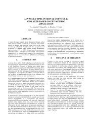
wideband rf signal digitising for high purity spectral analysis
wideband rf signal digitising for high purity spectral analysis
wideband rf signal digitising for high purity spectral analysis

Create successful ePaper yourself
Turn your PDF publications into a flip-book with our unique Google optimized e-Paper software.
WIDEBAND RF SIGNAL DIGITISING FOR HIGH PURITY SPECTRALANALYSISYuri Artyukh, Ivars Bilinskis, Eugene Boole, Alexander Rybakov, Vadim VedinInstitute of Electronics and Computer Science, University of Latvia,14 Dzerbenes Str., Riga LV-1006, LATVIA. bilinski@edi.lvABSTRACTAn advanced RF <strong>signal</strong> digitiser based on the DASPapproach is discussed. In comparison with theconventional RF <strong>signal</strong> <strong>digitising</strong>, it is characterised notonly by a wide (669 MHz) bandwidth but it also makes itpossible to obtain <strong>high</strong> <strong>purity</strong> spectrograms.1. INTRODUCTIONWideband RF <strong>signal</strong> <strong>digitising</strong> is a quite demanding task.There are two most often used typical approaches to RF<strong>signal</strong> <strong>digitising</strong>. The first approach is based on direct RF<strong>signal</strong> <strong>digitising</strong> at a very <strong>high</strong> (up to GHz) samplingrate, using <strong>for</strong> that <strong>wideband</strong> <strong>high</strong>-speed A/D converters.While it leads to obtaining a broad alias-free frequencybandwidth, the technical realization of such <strong>digitising</strong> is<strong>high</strong>ly complicated. In addition, the <strong>high</strong>-speed A/Dconverters usually are limited in resolution down to 6-8bits.The second well-known approach is based on RFdown-conversion with the following digitisation of theconverted <strong>signal</strong> at a relatively low sampling rate. Thisapproach is simpler in realization and provides betterresolution but it is applicable only <strong>for</strong> a limitedfrequency band.An alternative approach is suggested and discussedin this paper. It is based on usage of so called DigitalAlias-free Signal Processing (DASP) technology [1].This technology takes into account one important fact:the most of present-day A/D converters have an inputbandwidth much wider than the sampling rate. So inconventional application the maximum availablesampling rate limits the range of digital alias-free <strong>signal</strong>presentation down to the Nyquist frequency. The DASPtechnology avoids this limitation <strong>for</strong> many importantapplications and allows utilising the actual potential ofA/D converters almost fully.Generally application of DASP is advantageous asit leads to obtaining both the wide bandwidth and thesimplicity in realization. However the DASP technologyis specific. To achieve the essential alias eliminationeffect, <strong>signal</strong> sample values are taken at predeterminednon-uni<strong>for</strong>mly spaced time instants placed on a regulartiming grid. In this case the available frequencybandwidth is defined only by the step of this grid andcan reach GHz range. On the other hand the samplingintervals typically contain a relatively large number ofthese steps so that minimum sampling interval is not lessthan the A/D converter allows. Successful elimination ofaliasing is achieved by using this kind of <strong>digitising</strong>together with the usage of proper <strong>signal</strong> processingalgorithms. The upper frequency of input <strong>signal</strong>sdigitised in accordance with the DASP technology, in awide application area, can substantially exceed the meansampling rate. In addition, designs of this kind ofdigitisers are relatively simple <strong>for</strong>asmuch as thecommonly used electronic devices can be employed.A few models of the DASP digitisers have beenearlier developed and made [2-4]. In combination withspecial DASP algorithms, they provide <strong>for</strong> both <strong>wideband</strong>width and simplicity of the hardware. For example,the DASP digitiser of “DASP-Lab System” [2] isapplicable in 1.2 GHz bandwidth while the meansampling rate is only 80 MSPS. An advanced DASPdigitiser is discussed in this paper. In comparison withthe previous models, it is characterised not only by awide (669 MHz) bandwidth but it also makes it possibleto obtain <strong>high</strong> <strong>purity</strong> spectrograms.2. THE PROBLEM TO BE SOLVEDThe Spurious-Free Dynamic Range (SFDR) is a vitaldynamic characteristic of digitisers to be used <strong>for</strong> widedynamic range and <strong>high</strong> frequency applications.By definition the SFRD is the ratio between themaximum <strong>signal</strong> component and the largest distortioncomponent in <strong>signal</strong> spectrum. Generally the maximumavailable SFDR of a digitiser is defined by dynamiccharacteristics of A/D converter being used <strong>for</strong> <strong>signal</strong><strong>digitising</strong>. However usually there are some additionallimitations <strong>for</strong> SFDR caused by peculiarities of the A/Dconverter application in digitiser design. Specifically,one of the possible reasons of additional SFDR limitingis a periodically repeated offset of the actual samplinginstants relative to the points of strictly uni<strong>for</strong>m timinggrid. This offset causes spurious <strong>spectral</strong> components,which additionally narrow the SFDR of the digitisers.Simulation of <strong>signal</strong> sampling with a slight periodicoffset shows that even as small as picosecond offsetproduces spurious components that essentially decreasethe SFRD down to 50-60 dB in 500-700 MHz bandwidth(Figure 1).For the conventional (uni<strong>for</strong>m) <strong>signal</strong> samplingsuch offset can be caused by a periodic spuriousmodulation of the clock source (such as by a switchingpower supply). However a careful PCB design andnarrow-band filtering the reference frequency can
significantly suppress such modulation (down to parts ofps) to reach a widest available SFDR.Figure 1. FFT <strong>for</strong> 533 MHz sine-wave <strong>signal</strong> sampled at1600 MHz rate; the sampling instants are displaced fromthe regular location by ±2 ps with 100 MHz periodicityAs <strong>for</strong> DASP digitisers, basically the offset can becaused by an inaccuracy at generation of the samplingpulses at the required non-uni<strong>for</strong>mly spaced timeinstants.Reaching required picosecond accuracy ofsampling pulse generation is a very serious problem <strong>for</strong>designing the <strong>wideband</strong> DASP digitisers as the circuits<strong>for</strong> the sampling pulses generation are relativelycomplicated. Specifically, the most widespread approachto the non-uni<strong>for</strong>m sampling pulse generation is basedon usage of digitally controllable delay lines that isdriven by a low-jitter clock source. Theoretically in thisway it is possible to spot the sampling instants in anydesired places with accuracy limited only by the delayline pe<strong>rf</strong>ormance. Seeing that currently top-leveldigitally controllable delay lines offer the increment ofpicosecond range, the GHz range of equivalent samplingrate <strong>for</strong> DASP is quite practicable.In the previous models of DASP digitisers we used<strong>for</strong> sampling pulse generation the <strong>high</strong>-pe<strong>rf</strong>ormanceprogrammable delay chips MC100EP195 from “ONSemiconductor”. This chip provides about 10 psincrement in 10 ns delay range, making it well suited todriving by the conventionally used 100 MHz clocks.Generally these digitiser models have provided thedesign frequency bandwidth but, un<strong>for</strong>tunately, theycould not support the required picosecond accuracy ofsampling pulse generation. This was, first of all, due tothe too large differential non-linearity of the delay chipsand temperature drifts of the delay range. For thesereasons, SFDR of the previous DASP digitiser modelstypically does not exceed 35-40 dBFS.To provide much better <strong>spectral</strong> <strong>purity</strong> (in terms ofSFDR), a new advanced version of DASP digitisers hasbeen designed and made. This version is subsequentlyreferred to as DIGITISER.3. DESIGN OF THE DIGITISERAs <strong>for</strong> some previous modes of DASP digitisers, the<strong>high</strong>-pe<strong>rf</strong>ormance 12-bit A/D converter AD9433 from“Analog Devices” has been chosen <strong>for</strong> DIGITISERdesign. This converter provides 700 MHz analogbandwidth at sampling rate up to 125 MSPS. Thus, in itsconventional applications the alias-free analogbandwidth does not exceed Nyquist’s frequency 62.25MHz. The DIGITISER should be able to utilize the <strong>wideband</strong>width of this A/D converter almost fully.Structurally the designed DIGITISER (Figure 2)fully con<strong>for</strong>ms to the patented solution [5] where thesampling pulses are <strong>for</strong>med through clock frequencycontrollable dividing and controllable delaying of thedivided pulses. A pseudo-random number generator(PRG) provides digitally such control.Generally the patented solution tolerates differentrelations between the mentioned digital (clock frequencydividing) and analog (pulse delaying) operations. In ourcase an emphasis was made on digital operations atmuch <strong>high</strong>er clock frequency (669.3266 MHz instead ofpreviously used 100 MHz). It was supposed that in thiscase a very accurate low-jitter timing grid with 1.494 nsstep could be supported exclusively by digital means.SAMPLING PULSE FORMER669.3 800 MHzClockPRGDivider by 9 to 16(MC100EP016)Digital controlShaperInputFine tuningDelay block0/625 0/747 psADC(AD9433)FIFOFigure 2. Schematic block diagram of the DIGITISERThe 1.494 ns step itself can support alias-freeanalog bandwidth up to 335 MHz approx. However toreach wider (>500 MHz) bandwidth <strong>for</strong> DASPapplications the step size must be at least halved. To dothat, an additional one-step controllable delay block isapplied. By definition this block should be extremeprecise. To provide required precision, it was designedon the basis of an adjustable with 33 ps/step delay line(VDJ1010 from ELMEC TECHNOLOGY), a specialmeans <strong>for</strong> fine delay tuning with picosecond precision,and <strong>high</strong>-speed multiplexer. Such structural solution ofthe sampling pulse <strong>for</strong>mer provides the following designcharacteristics of the sampling process:• Real sampling rate 53.546 MSPS• Equivalent sampling rate 1338.653 MSPS• Alias-free analog bandwidth to 669.326 MHzGenerally it was supposed that in this case the periodicoffset of sampling instants would not exceed a fewpicoseconds under temperature-variable operatingconditions, resulting in the SFDR not less than 50 dB infull input <strong>signal</strong> bandwidth.The mentioned structural solution of theDIGITIZER has been embodied as a single compact(185x162mm) board that can be connected to PC via itsparallel port supporting EPP mode of data exchanging(Figure 3). The board may be housed in a standardenclosure and powered via an external AC/DC adapter.
In the process of design a special attention has beenfocused on very careful PCB design to optimize theprinted connections between components most critical tointe<strong>rf</strong>erence and avoid both a distortion of the input RF<strong>signal</strong> and a ringing of <strong>high</strong> frequency digital <strong>signal</strong>s.missing uni<strong>for</strong>m sample values with the estimated <strong>signal</strong>values leads to significant improvement of accuracyespecially if the process is repeated in an iterative way.Let us consider this method <strong>for</strong> <strong>signal</strong> <strong>spectral</strong> <strong>analysis</strong>and wave<strong>for</strong>m reconstruction in some detail.4.1.1. Introduction of thresholdsAt first, the <strong>spectral</strong> estimates are calculated on the basisof DFT as follows:2a π , (1)N∑ − 1( 0)( fk) = x(ti)cos(2 fkti)N i = 02b π , (2)N∑ − 1( 0)( fk) = x(ti)sin(2 fkti)N i = 0A(+ )]220)( fk) = [ a(0)( fk)] [ b(0)( f . (3)kFigure 3. Design of the DigitizerIt is important that the most of digitiser’s digitaloperations pe<strong>rf</strong>ormed at low frequencies (such ascontrolling the process of sampling pulse generation,data buffering, inte<strong>rf</strong>acing with PC) were implementedin a specialized PLD chip. In this way it was possible notonly to simplify design but also achieve the <strong>high</strong>reliability in operation.4. EXPERIMENTAL EVALUATION OFPERFORMANCE CHARACTERISTICSEvidently the SFDR <strong>for</strong> the DIGITISER cannot be widerthan <strong>for</strong> the A/D converter being used (in our case –AD9433 from “Analog Devices”). However theproducer of this device specifies its dynamicpe<strong>rf</strong>ormance only up to 350 MHz input <strong>signal</strong>frequencies. In particular, the converter can provideSFDR about 67 dBFS at 250 MHz and about 60 dBFS at350 MHz. Presumably the SFRD at the <strong>high</strong>e<strong>rf</strong>requencies can be considerably less. Hereby thepracticable SFDR of the DIGITIZER within the range50-60 dBFS can be considered as close to the maximumpossible. The actual dynamic characteristics of theDIGITIZER have been evaluated experimentally.4.1. Iterative approach to spectrum <strong>analysis</strong> andwave<strong>for</strong>m reconstructionLet’s note once more that specialized DASP algorithmsshould be used to process non-uni<strong>for</strong>mly sampled<strong>signal</strong>s. The most popular method <strong>for</strong> processing such<strong>signal</strong>s is so-called zero padding method.According to this method, zeroes are used <strong>for</strong>replacing the missing <strong>signal</strong> sample values. Howeverthat actually leads to introduction of significant errorsobserved in spectrograms as <strong>high</strong> background noise. Inthe considered case, an iterative approach to <strong>spectral</strong><strong>analysis</strong> and wave<strong>for</strong>m reconstruction was used. It isbased on substitution of zeroes at the places of theThe index in the round brackets (in this case (0)) showsthe ordering number of iteration. The estimate (3) is usedto define some initial threshold <strong>for</strong> further iterativeoperations.In general, the iterative approach to spectrum<strong>analysis</strong> and wave<strong>for</strong>m reconstruction is based on theidea that a priori in<strong>for</strong>mation has to be used as fully aspossible. Zero padding is a crude method and itsapplication leads to introduction of substantial errors.When even approximate estimates of the <strong>signal</strong> samplevalues are used <strong>for</strong> replacement of those zeroes, thementioned errors could be reduced dramatically.There<strong>for</strong>e it is essential how the <strong>signal</strong> value estimationis organized. A step-by-step approach to that taskdecision has been used. The more powe<strong>rf</strong>ul <strong>signal</strong>components are estimated first; then the components thatare less powe<strong>rf</strong>ul and so on.Such an approach makes sense as the absoluteparameter estimation errors tend to be equal underspecific <strong>signal</strong> to noise ratio. There<strong>for</strong>e the relativeerrors are smaller <strong>for</strong> the more powe<strong>rf</strong>ul components. Torealize this approach, threshold levels are introduced.The <strong>signal</strong> components above the threshold are estimatedfirst. Then the inverse DFT is carried out and the missingsample values are substituted by the correspondinginstantaneous values of the roughly reconstructedwave<strong>for</strong>m. Then the obtained <strong>signal</strong> sample valuesequence is used <strong>for</strong> repeated DFT. Now it provides<strong>spectral</strong> estimates significantly more accurate. At thenext step, the threshold level is lowered and thecomponents above it are estimated again. The process iscontinued in this way <strong>for</strong> a given number of cycles.The first threshold is set up at the levelU0= µ(0)max ( A(0)( fk)), 0 < µ(0)< 1 (4)kwhere the initial relative threshold often is chosen at thelevel µ (0) = (0.7…0.9). The <strong>signal</strong> components exceedingthe given threshold A (0) (f k ) > U 0 are estimated at thecorresponding frequencies.All estimated <strong>signal</strong> components with power belowthe first threshold level are excluded from thespectrogram in the following way:
Y( n+1)⎪⎧Y(n)[ k][ k]= ⎨⎪⎩0ififYY( n)( n)[ k]> U[ k]≤ Unn(21)and they are processed in the same way in the nextiteration cycle: wave<strong>for</strong>m reconstruction is follow as theinverse FFT:M∑ − 12πik1jMy( n + 1)[ i]= Y(n + 1)[ k]e , i = 0, M −1(22)M k = 0and the initial samples are built in the reconstructedr r rvector of wave<strong>for</strong>m q = xy ( ( n + 1)) .4.2. Some experimental resultsTo evaluate the DIGITISER actual pe<strong>rf</strong>ormanceevaluation software has been developed. This softwarewas based on the mentioned DASP algorithm andprovides processing of 1K samples (accumulated in realtime during 19.124 µs) in each <strong>analysis</strong> cycle, resultingboth in spectrum of input <strong>signal</strong> and its wave<strong>for</strong>m.In the case of <strong>spectral</strong> <strong>analysis</strong> the software detectsand estimate up to a few tens of <strong>spectral</strong> components ofthe <strong>signal</strong> (in order of decreasing their power) withcalculated frequency resolution about a few Hz. Next is<strong>signal</strong> wave<strong>for</strong>m reconstruction from these components.As a result the wave<strong>for</strong>m and spectrum of the input<strong>signal</strong> are displayed in graphical <strong>for</strong>m after eachanalyzing cycle. One can use zoom to see any selectedarea of the general views in more details. Figure 4illustrates these capabilities in the case of analyzing apulse sequence.alternatively by a <strong>high</strong>-pe<strong>rf</strong>ormance digitizingoscilloscope (TDS 3052B) providing 5GHz/s real timesampling rate and 500 MHz bandwidth.Figures 5-6 show the <strong>analysis</strong> results <strong>for</strong> two-tonetest <strong>signal</strong>s. Spectrums of these <strong>signal</strong>s are similar to theprevious one in sense of spurious component absence,noise floor and the expected SFDR. Figure 5 directlyshows that even <strong>signal</strong> component so small as –54 dBFScan be clearly detected on the background of noises.As <strong>for</strong> evaluation of other dynamic characteristics,they were very close to the standard specifications of theA/D converter.Figure 5. Two-tone <strong>signal</strong> <strong>analysis</strong> when the tones aresimilar in amplitudeFigure 4. 100 MHz pulse sequence analyzingAs in the other cases, the wave<strong>for</strong>m is shown in digits ofA/D conversion vs. time in µs; the spectrum is shown indBFS vs. frequency in MHz.The spectrum clearly shows all expected harmoniccomponents of the <strong>signal</strong>, including two aliasings from700 and 800 MHz harmonic components that exceed669.3 MHz Nyquist’s limit; spurious components in factare not detected. The observed level of the noise flow(about -60 dBFS) suggests the actual SFDR estimationas better than 60 dBFS. As <strong>for</strong> the reconstructedwave<strong>for</strong>m, it is fully defined by the spectrum and wellcon<strong>for</strong>ms to the view of the same <strong>signal</strong> obtainedFigure 6. Two-tone <strong>signal</strong> <strong>analysis</strong> when the tones differin amplitude considerably5. SUMMARY OF SPECIFICATIONSInput rangeAnalog bandwidthResolutionDASP sampling mode:Real sampling rateEquivalent sampling rateAlias-free analog bandwidthSFDRPeriodic sampling mode:Sampling rateAlias-free analog bandwidth2 V p-p0.1-700 MHz12 bits53.546 MSPS1338.653 MSPS0.1-669.3 MHz> 55 dBFS74.37 MSPS0.1-37.1 MHz
Trigger (programmable)FIFO sizeInte<strong>rf</strong>acingConnectors:Input – SMAExternal trigger – BNCEPP Port – DB25Board dimensionEnclosure dimensionsPower supply6. CONCLUSIONexternal or internal32K Samplesvia parallel PC port185X162mm185x192x55mm7.5V/1.1AThe considered DIGITISER under DASP provides <strong>high</strong><strong>spectral</strong> <strong>purity</strong> that is near to the achievable by the used<strong>high</strong>-pe<strong>rf</strong>ormance 12-bit A/D converter itself. However,it should be emphasized, that this <strong>high</strong> dynamicpe<strong>rf</strong>ormance has been achieved in alias-free way in thewhole frequency range up to 669 MHz. We are notaware of any other available technique of RF <strong>signal</strong><strong>digitising</strong> and digital analysing that permits to achievecomparable dynamic pe<strong>rf</strong>ormance by using the indicatedtype of A/D converter.7. REFERENCES[1] I. Bilinskis, I. Mednieks. Introduction to Digital Alias-freeSignal Processing. Institute of Electronics and ComputerScience, Riga, “Dasp Lab Ltd.”, London 2001, 65.p.[2] Yu. Artyukh, I. Bilinskis, M. Greitans, V. Vedin. “SignalDigitizing and Recording in the DASP-Lab System”.Proceeding of the 1997 International Workshop onSampling Theory and Application, June, 1997, Aveiro,Portugal, p.357-360.[3] Yu. Artyukh, I. Bilinskis, V. Vedin. “Hardware core of theFamily of Digital RF Signal PC-based Analyzers”.Proceeding of the 1999 International Workshop onSampling Theory and Application, August 11-14, 1999,Loen, Norway, p.177-179.[4] Yu. Artyukh, V. Bespal’ko, E. Boole. “Analog <strong>signal</strong>digitizer adapted to experimental evaluation of DASPalgorithms”. Proceeding of the 8 th Biennial ElectronicsConference, October 6-9, 2002, Tallinn, Estonia, p. 231-232.[5] J. Artjuhs, I. Bilinskis. “Method and apparatus <strong>for</strong> aliassuppressed digitizing of <strong>high</strong> frequency analog <strong>signal</strong>”.European patent application 02001248.8 Published23.07.2003, Bulletin 2003/30.