reactor modeling and simulation of catalytic reforming process
reactor modeling and simulation of catalytic reforming process
reactor modeling and simulation of catalytic reforming process
- No tags were found...

Create successful ePaper yourself
Turn your PDF publications into a flip-book with our unique Google optimized e-Paper software.
PPeet ttr rool lleeuum && CCooaal llISSN 1337-7027Available online at www.vurup.sk/pcPetroleum & Coal 48 (3), 28-35, 2006REACTOR MODELING AND SIMULATION OFCATALYTIC REFORMING PROCESSS. R. Seif Mohaddecy 1 , S. Zahedi 2 , S. Sadighi 1 , H. Bonyad 11 Catalytic Reaction Engineering Department, Catalyst ResearchCenter, RIPI, RIPI Boulivard, Old Qom Road, Tehran, P.O. Box:18745-4163, 2 Chemical Engineering Department, Engineering Faculty,Tarbiat Modares University, Tehran, e-mail:seifsr@ripi.irReceived April 10, 2006; accepted November 24, 2006AbstractOne <strong>of</strong> the most important <strong>and</strong> critical <strong>process</strong>es in petroleum refineries is <strong>catalytic</strong> <strong>reforming</strong> in which highoctane gasoline <strong>and</strong> valuable aromatics such as Benzene, Toluene <strong>and</strong> Xylene (B.T.X.) are produced. In view<strong>of</strong> the importance <strong>of</strong> this <strong>process</strong> for producing gasoline, <strong>simulation</strong> <strong>of</strong> <strong>catalytic</strong> <strong>reforming</strong> <strong>process</strong> <strong>and</strong>prediction <strong>of</strong> vital parameters such as octane number, Liquid Hour Space Velocity (LHSV), <strong>reactor</strong> inlettemperatures, yield <strong>and</strong> catalyst life aiming at <strong>process</strong> optimization is <strong>of</strong> prime importance. In this work, theoldest kinetic model mentioned for this unit is reconsidered. The accuracy <strong>of</strong> the model is compared with thecollected data from Tehran refinery <strong>and</strong> results <strong>of</strong> Petro-Sim simulator, one <strong>of</strong> the newest for <strong>simulation</strong> <strong>of</strong>petroleum refinery <strong>process</strong>es. The results show that this model has relatively acceptable ability to predictoctane number, outlet temperature <strong>of</strong> <strong>reactor</strong>s <strong>and</strong> yield.Keywords: Catalytic Naphtha Reforming, Petro-Sim, Modeling, Simulation1. IntroductionThe <strong>catalytic</strong> <strong>reforming</strong> <strong>process</strong> is one <strong>of</strong> the most critical operations in petroleum refineries toproduce gasoline with high octane number. This <strong>process</strong> uses naphtha or cracking oil as feedstockto produce rich aromatic compounds <strong>and</strong> high octane value liquid products through reactions suchas aromatization, cyclization <strong>and</strong> hydrocracking. At the same time, it produces hydrogen (H) <strong>and</strong>liquefied petroleum gas (LPG) as its by-products. In this <strong>process</strong>, products with different octanenumber are produced unlike the production <strong>of</strong> certain octane number in others such as <strong>catalytic</strong>cracking, alkylation <strong>and</strong> isomerization.Industrial catalysts used in recent <strong>catalytic</strong> <strong>reforming</strong> units are consisted <strong>of</strong> Gama Aluminasupport, metals such as Platinum, Rhenium, Germanium, <strong>and</strong> Iridium, less than one weightpercent, <strong>and</strong> additives such as chlorine to increase isomerization reactions. Usually, feed <strong>of</strong><strong>catalytic</strong> reformers is Heavy Straight Run Naphtha (H.S.R.G) including four hydrocarbon groups:Paraffins, Olefins, Naphthenes <strong>and</strong> Aromatics (P.O.N.A) with carbon number from 5 to 10. Thedesign or <strong>simulation</strong> <strong>of</strong> the <strong>catalytic</strong> <strong>reforming</strong> <strong>reactor</strong> is very difficult because <strong>of</strong> intricacy <strong>of</strong><strong>catalytic</strong> <strong>reforming</strong> feedstock, high operating temperature <strong>of</strong> <strong>reactor</strong>s, <strong>and</strong> the complex reactions inthe <strong>reactor</strong>.In the <strong>catalytic</strong> <strong>reforming</strong> <strong>process</strong>, seven types <strong>of</strong> reactions are taken place as the following:1-Dehydrogenation 2-Isomerization 3-Hydrocracking 4-Cyclization5-Hydrogenolysis 6-Aromatization 7-Coke FormationA typical <strong>of</strong> these group reactions is shown in figure 1.
S. R. Seif Mohaddecy et al./Petroleum & Coal 48(3) 28-35 (2006) 29Figure 1. A typical <strong>of</strong> reactions in the Catalytic Reforming ProcessSome <strong>of</strong> these reactions such as cyclization <strong>and</strong> aromatization are desirable because <strong>of</strong>increasing octane number. On the other h<strong>and</strong>, coke formation <strong>and</strong> coke deposition, causing thedeactivation <strong>of</strong> the catalyst, are undesired reactions.The <strong>catalytic</strong> <strong>reforming</strong> <strong>process</strong> discussed in this paper is the Semi-Regenerative type (figure2) including <strong>of</strong> three <strong>reactor</strong>s. Due to the endothermic nature <strong>of</strong> most <strong>catalytic</strong> <strong>reforming</strong> reactions,there is a furnace (heater) at the inlet <strong>of</strong> each <strong>reactor</strong> to heat up the feed to the requiredtemperature.Figure 2. Catalytic Reforming Flowchart (Semi-Regenerative)A separator after the <strong>reactor</strong>s recirculates light gases such as hydrogen <strong>and</strong> methane to thebeginning <strong>of</strong> the <strong>process</strong> by a recycle compressor. Liquid product from the separator enters thestabilizer tower to improve vapor pressure (RVP) <strong>of</strong> gasoline. After that, bottom <strong>of</strong> the tower, calledreformate, will be sent to the gasoline pool.Normally, <strong>catalytic</strong> <strong>reforming</strong> <strong>process</strong> includes <strong>of</strong> three or four adiabatic <strong>reactor</strong>s with a furnacebefore each <strong>of</strong> them. Initially, the feed will be mixed with the recycle stream <strong>and</strong> heated, thenentered the first <strong>reactor</strong> at a definite temperature.In the present work, Smith model for <strong>catalytic</strong> <strong>reforming</strong> <strong>reactor</strong>s will be developed entirely.Then resulted data from the model will be compared to the ones from Tehran refinery <strong>catalytic</strong>reformer <strong>and</strong> Petro-Sim simulator to evaluate the accuracy <strong>of</strong> the model.
S. R. Seif Mohaddecy et al./Petroleum & Coal 48(3) 28-35 (2006) 302. Catalytic Reforming Process ModelingCatalytic <strong>reforming</strong> <strong>process</strong> is <strong>of</strong>ten modeled based on the following factors:1-The number <strong>of</strong> reactive species2-The type <strong>of</strong> used kinetic modelBecause <strong>of</strong> many components as reactants or intermediate products in the reactive mixture<strong>and</strong> new reactions as a consequence, it will extremely make a sophisticated situation for <strong>modeling</strong>the <strong>process</strong>. To mitigate the complication, reactants in the mixture are classified in certain <strong>and</strong>limited groups, called Pseudo Components. The number <strong>of</strong> selected pseudo components in thefeed is a characteristic factor, the key in presented models.Arrhenius <strong>and</strong> Langmuir–Hinshelwood kinetics are used for <strong>catalytic</strong> <strong>reforming</strong> models. Itshould be noted that for all <strong>of</strong> the presented models, the reactions are considered as Pseudohomogen that some <strong>of</strong> them will be noted briefly:Smith proposed the first kinetic model for <strong>catalytic</strong> <strong>reforming</strong> <strong>process</strong> in 1959 [1] . In this modelhe assumed that naphtha includes <strong>of</strong> three fundamental groups: paraffins, naphthens, <strong>and</strong>aromatics. Moreover, he introduced hydrogen, Ethane, propane, <strong>and</strong> butane into the system inaddition to these groups. Based on these assumptions, he could give a simple <strong>and</strong> accurate kineticfor <strong>catalytic</strong> <strong>reforming</strong> <strong>process</strong>. Reactions according to Smith model are as the following:1- Naphthenes to aromatics2- Naphthenes to paraffins3- Hydrocracking <strong>of</strong> paraffins4- Hydrocracking <strong>of</strong> naphthenesOne year later in 1960, the other one was introduced by Krane <strong>and</strong> his colleagues [2] . In thismodel, feed was consisted <strong>of</strong> 20 pseudo components <strong>and</strong> hydrocarbons from 6 to 10 carbonatoms. Moreover, reaction network was contained <strong>of</strong> 53 reactions. Arrhenius kinetic model is usedfor mentioned models.The other models are proposed by Zohrov, Heningsen, Kmak, <strong>and</strong> Marin [3], [4], [5], [6] . Kmak usedLangmuir kinetic model for <strong>catalytic</strong> <strong>reforming</strong> <strong>process</strong> for the first time in 1972 [5] . Marin <strong>and</strong> hiscolleagues developed that in 1983, as if it was consisted <strong>of</strong> naphtha from 5 to 10 carbon atoms <strong>and</strong>reaction network includes <strong>of</strong> 23 pseudo components [6] . In 1997, Froment model [7] was developedby Umesh Taskar so that it included <strong>of</strong> 35 pseudo components in the reaction network, <strong>and</strong> 36reactions has been observed [8] . As a consequence <strong>of</strong> using Arrhenius kinetic, a well-known modelhas been proposed by Padmavathi [9] in 1997 in which 26 pseudo components in reaction mixturewere used. In this model, the following pseudo components are considered:1- Alkyl Cyclohexane (ACH)2-Alkyl cyclopentane (ACP)3- Normal Paraffins (NP)4-Isoparaffins (IP)5-Aromatics (A)6-Hydrogen (H 2 )7-Light Hydrocarbons (C1 to C5)Krane model was modified by Ancheyta [10] in which naphtha contained 1:11 paraffinic, 6:11naphthenic <strong>and</strong> aromatic hydrocarbons. Indeed the reaction <strong>of</strong> cyclohexane formation fromcyclopantane <strong>and</strong> paraffins isomeration are considered in this model unlike Krane model. Morerecently, Liang et. al. [11] developed a physical model to simulate a <strong>catalytic</strong> reformer unit with 4<strong>reactor</strong>s in series. kinetics <strong>and</strong> thermodynamic equations were selected to describe the naphtha<strong>catalytic</strong> <strong>reforming</strong> reactions characterized based on idealizing the complex naphtha mixture byrepresenting the paraffin, naphthene <strong>and</strong> aromatic groups by single compounds.In this paper, one <strong>of</strong> the presented models, Smith model, was used for <strong>simulation</strong> <strong>of</strong> a Semi-Regenerative <strong>process</strong> with 3 <strong>reactor</strong>s in series. To evaluate the accuracy <strong>of</strong> the model, the actualdata from Tehran refinery <strong>catalytic</strong> <strong>reforming</strong> unit were used. Furthermore, <strong>simulation</strong> results werecompared with Petro-Sim s<strong>of</strong>tware.3. Development <strong>of</strong> Smith Model for Catalytic Reforming ProcessTo simulate <strong>catalytic</strong> <strong>reforming</strong> unit, the simplest model, Smith model, is preferentially used. Asmentioned previously, for this model feed will be classified in three general groups: aromatics,naphthens <strong>and</strong> paraffins. In addition, hydrogen, methane, Propane, butane, <strong>and</strong> pentane are alsoconsidered.
S. R. Seif Mohaddecy et al./Petroleum & Coal 48(3) 28-35 (2006) 31Reactions within the model are classified in four groups. In order <strong>of</strong> significance, they are asthe following:1- Naphthenes to aromaticsnaphthene s ↔ aromatics + 3H 2Rate constants concerning this reaction will be [1] :46045( 46.15 − )T3Ke1= e , atm.(1)34750(23.21 − )molesTkf 1= e ,2(2)2- Naphthenes to paraffinsnaphthene + H 2↔paraffin( hr.)(lb.cat.)(atm.)Rate constants concerning this reaction will be [1] :8000( −7.12+ )T−1Ke 2= e , atm.(3)59600(35.98 − )molesTkf 2= e ,2(4)3- Hydrocracking <strong>of</strong> paraffinsCnH2n( hr.)(lb.cat.)(atm.)n −1n+ 2( paraffin)+ H2⎯⎯→3 155∑i=1Rate constants concerning this reaction will be [1] :tC Hkf 3− rnaphthene_ cracking= pp(5)Pkf 3moles( hr.)(lb.cat.)i62300(42.97 − )T= e ,(6)4 – Hydrocracking <strong>of</strong> naphthenesn nCnH2n( naphthene)+ H2⎯⎯→3 155∑i=1C HiIn this case, rate constants concerning this reaction will be [1] :kf 4− rnaphthene_ cracking= pN(7)Pkf 4e62300(42.97 − )T,tmoles( hr.)(lb.cat.)2i+2= (8)Due to developing rate equations, mass <strong>and</strong> energy balance have been resulted in thefollowing relations:3dN kf 1PAPAH 2= PN( Ke1− )(9)dV KP= P(10)2i+2R e1N3dN kN f 1PAPHkfP k2 2A f 4− PN( Ke1− ) − PN( Ke2− ) −dVRKe1PNKe2PNPHP2 tdN kP f 2P kA f 3PN( Ke2− ) − PPdVRKe2PNPHPt= (11)2N
S. R. Seif Mohaddecy et al./Petroleum & Coal 48(3) 28-35 (2006) 32dTdVRk−Pf 4tk=−Kf1e1P ( KNn−3P()3e1PAP−P3H2NΔHf)(NCt1Pkf) −K2e2P ( KNe2PA−P PN H2ΔHf)(NCt2Pkf) −Pt3ΔHfPN(N Ct3Pn)( )3(12)Where n is the number <strong>of</strong> each pressumed carbon <strong>of</strong> pseudo components [1] which is67 forthe feed in the model [1] .4. Results <strong>and</strong> DiscussionAfter developing the model, it should be scaled up to the industrial unit. An optimizationsubroutine has been used to determine the coefficients so that a suitable consistency between theunit <strong>and</strong> the model can be achieved. In this subroutin, Levenburg-Marquardt optimization algorithmis used <strong>and</strong> the following target function is optimized:f=n∑i=1( (13)220.5( Ciexp− Cipredict) + 0.5( Tiexp−Tipredict) )The magnitudes <strong>of</strong> calculated constants are presented in Table 1 for Tehran refinery.Table 1. Reaction Constants calculatedReaction Number123Reaction NameAromaticProductionParaffinsproduction fromaromaticsParaffinsHydrocrackingk018.5926.7442.97ER(Rankin)3480758591628574NaphthenesHydrocracking42.9761224In a <strong>catalytic</strong> <strong>reforming</strong> <strong>process</strong>, major operating parameters are:1- Inlet <strong>and</strong> outlet temperature <strong>of</strong> <strong>reactor</strong>s2- Total yield3- Octane numberTo measure the accuracy <strong>of</strong> the model, resulted data from the model are compared to theones from Petro-Sim simulator <strong>and</strong> actual data. The comparison between outlet temperaturesobtained by the model, Petro-Sim <strong>and</strong> the actual data for three <strong>reactor</strong>s are presented in figures 3to 5.Another significant operating parameter in <strong>catalytic</strong> <strong>reforming</strong> <strong>process</strong> is yield which is definedthe ratio <strong>of</strong> reformate volume flow rate to the feed volume flow rate. In figure 6 the comparisonbetween the yield <strong>of</strong> the unit, the model <strong>and</strong> Petro-Sim has been shown.Octane number is one <strong>of</strong> the other important parameters in <strong>catalytic</strong> <strong>reforming</strong> <strong>process</strong>. Thisparameter has been calculated by the Octane Index method [12] . The comparison among octanenumber <strong>of</strong> the unit <strong>and</strong> the model has been shown in figure 7.
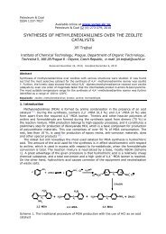
S. R. Seif Mohaddecy et al./Petroleum & Coal 48(3) 28-35 (2006) 33Tout R # 1467462457452447442170 190 210 230 250Days on StreamTout(1)-ActualTout(1)-modelPetroSimFigure 3. Comparison <strong>of</strong> Outlet Temperature ( 0 C) in the First <strong>reactor</strong>490485Tout R # 2480475470465ModelActualPetroSim460170 190 210 230 250Days on StreamFigure 4. Comparison <strong>of</strong> Outlet Temperature ( 0 C) in the Second <strong>reactor</strong>500495Tout R # 3490485480475470170 190 210 230 250Days on StreamTout(3)-ActualTout(3)- modelPetroSimFigure 5. Comparison <strong>of</strong> Outlet Temperature ( 0 C) in the Third <strong>reactor</strong>
S. R. Seif Mohaddecy et al./Petroleum & Coal 48(3) 28-35 (2006) 34Yield(Vol%)100806040200170 190 210 230 250Days on streamYield-ActualYield -Petro-SimYield-ModelFigure 6. Comparison <strong>of</strong> Total YieldRON102979287820 100 200 300 400Days On streamRON -ModelRON-Actual-PetroSim5. ConclusionsFigure 7. Comparison <strong>of</strong> RON Product1- Smith model, in spite <strong>of</strong> being old <strong>and</strong> simple, can result the acceptable estimation <strong>of</strong>operating conditions such as outlet temperature <strong>of</strong> the <strong>reactor</strong>s, octane number, yield <strong>and</strong> PONA.2- With consideration <strong>of</strong> suitable deactivation number, effect <strong>of</strong> time on the <strong>process</strong> can bediscussed.3- It was a consistency between Smith model <strong>and</strong> Petro-Sim in estimating operatingparameters.4- Due to the necessity <strong>of</strong> controlling the amount <strong>of</strong> benzene <strong>and</strong> aromatics in Gasoline, amodel for determining concentration <strong>of</strong> Benzene <strong>and</strong> aromatic should be developed.5- Comparison between Petro-Sim results <strong>and</strong> actual data showed the appreciated ability <strong>of</strong>this s<strong>of</strong>tware to simulate <strong>catalytic</strong> <strong>reforming</strong> unit.NotationSubscriptsC - concentration, moles per unit volumeA- aromatick - rate constant for forward reactions (variable dimension) exp - experimentalk 0 - frequency factor <strong>of</strong> forward reactionsi - reaction numberK - equilibrium constant (variable dimension)predict - predictedn- number <strong>of</strong> carbon atoms N - naphthenesN - mole numberP - paraffinsP - partial pressure (atm.)t - totalR- ideal gas constantsT - temperature (R)V R - volume <strong>of</strong> <strong>reactor</strong>Δ H - heat <strong>of</strong> reaction (Btu./ mol)C P - heat Capacity (Btu./mol F.)
S. R. Seif Mohaddecy et al./Petroleum & Coal 48(3) 28-35 (2006) 35References[1] Smith, R.B., Chem.Eng.Prog. , 1959, 55 (6), 76 – 80.[2] Krane, H.G.,“ Proceeding <strong>of</strong> the 5 th World Petroleum Congress “, 1959, pp 39- 51.[3] Zhorov, Y.M., Kinetika i Kataliz, 1965, 6(6), 1092 – 1098.[4] Henningsen, J., Chem.Eng. , 1970, 15, 1073 –1087.[5] Kmak, W.S., AIChE Meeting, Houston, TX, 1972.[6] Marin, G.B.; Froment, G.F., EFCE Publ. Ser., 1983, Vol 2. , NO.27, C 117.[7] Froment, G.F., Chem.Eng.Sci. , 1987, 42, 1073 – 1087.[8] Taskar, U., AIChE J., 1997, 43 (3), 740 – 753.[9] Padmavathi, G., J.Chem. Eng., 1997, 75, 930 – 937.[10] Ancheyta, J., Energy <strong>and</strong> Fuels, 2001, 15, 887 – 893.[11] Liang Ke-min, GUO Hai-yan, Pan Shie-wei, A study on naphtha <strong>catalytic</strong> <strong>reforming</strong> <strong>reactor</strong><strong>simulation</strong> <strong>and</strong> analysis, Journal <strong>of</strong> Zhejiang University Science, 2005 6B(6): 590-596.[12] Petro-Sim user Guide, KBC Advanced Technologies, KBC PROFIMATIC.