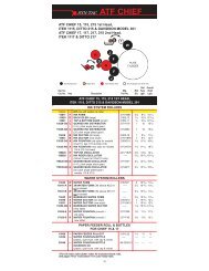
Ryobi 512 - ArdensParts.com
Ryobi 512 - ArdensParts.com
Ryobi 512 - ArdensParts.com

Create successful ePaper yourself
Turn your PDF publications into a flip-book with our unique Google optimized e-Paper software.
Crestline ® TMAltra Series DampenerInstallation Instructions<strong>Ryobi</strong> <strong>512</strong>X88-6910/98Rev-A
GENERAL INFORMATIONATTENTIONCRESTLINE ®ALTRA SERIES TMDAMPENEROWNER!Accel Graphic Systems provides parts and service through itsauthorized distributors and dealers. Therefore, all requests forparts and service should be directed to your local dealer.The philosophy of Accel Graphic Systems is to continually improveall of its products. Written notices of changes and improvementsare sent to Accel Graphic Systems' Dealers.If the operating characteristics or the appearance of your productdiffers from those described in this manual, please contact yourlocal Accel Graphic Systems Dealer for updated information andassistance.Always update your dampener when improvements are madeavailable, especially those related to safety.YOUR AUTHORIZED CRESTLINE ® ALTRA SERIES TMDEALER IS:THE SERIAL NUMBER OF YOUR CRESTLINE ® ALTRASERIES TM DAMPENER(S) IS:SAFETYINFORMATIONFOR YOUR SAFETY, DO NOT DISENGAGE OR REMOVE ANYGUARDS FROM THE CRESTLINE ® ALTRA SERIES TMDAMPENER. THE DAMPENER CONTAINS SOME INWARDROTATING ROLLER NIPS THAT CAN CAUSE INJURY IF LEFTUNGUARDED.2
GENERAL INFORMATIONBASICCONFIGURATIONOF CRESTLINE ®ALTRA SERIES TM 3b. 5/32" (4mm)c. 5/32" (4mm)IMa. 3/16" (5mm)POd. 5/32" (4mm)FRe. 5/32" (4mm)Adjustmentsa. Pan to Meteringb. Metering to Intermediatec. Intermediate to Oscillatord. Oscillator to Forme. Form to PlatePlateCylinderRoller DescriptionP = PanM = MeteringI = IntermediateO = OscillatorF = FormR = RiderTERMINOLOGYOPS = Operator's sideNOPS = Non-Operator's side#1 TOWER = Closest to feeder#2 TOWER = Closest to deliveryTECHNICALASSISTANCEFor technical assistance during the installation, please contact:ACCEL GRAPHIC SYSTEMS11103 Indian TrailDallas, TX 75229PHONE (972) 484-6808FAX (800) 365-6510E-MAIL accel@dallas.netWEB SITE www.accelgraphicsystems.<strong>com</strong>Crestline ® Altra Series TM is covered by U.S. Patents and patentspending.
GENERAL INFORMATIONREQUIRED TOOLSPhillips screwdriverStraight screwdriver.5mm Allen wrench3mm Allen wrench4mm Allen wrench5mm Allen wrench8mm wrench10mm wrench13mm wrench17mm wrench19mm wrench24mm wrench17mm socket3/32" punchHammerGear pullerSnap ring pliers4
PRE-INSTALLATION INFORMATIONCheck box and parts board to make sure all pieces are present andnothing has broken in shipping. Check the dampener for parallel(cutter bed works best). If dampener rocks, it needs to be realigned.Loosen tie bar bolts at OPS and align the frames on a flat surface.Retighten bolts.5
DISASSEMBLY1Disconnect press from power supply. Remove upper side coversat OPS & NOPS of printing towers as well as the slotted sheet metalguards covering the dampener. On the #2 tower, remove theslotted section of the cylinder guard by disconnecting the microswitcharm at NOPS and knocking out hinge pins. Save pins for reinstallationon the replacement guard provided. Also remove the water pansand any molleton covered roller from existing dampeners. Toremove the water forms, the cylinder gap must be positioned underroller.2Remove wiper bar (left subject arrow) by removing mountingbracket and tapping out bar. Also, remove water pan mountingbrackets (right subject arrow).3At OPS, remove pan roller drive arm (subject arrow) by removingE-rings at each end and pulling arm off.7
DISASSEMBLY4At OPS, remove E-ring and pull assembly (subject arrow) from endof pan roller shaft.5At OPS, remove 2 cap screws (subject arrow) and pull worm andworm gear assembly from end of pan roller shaft.6At NOPS, disconnect water ductor solenoid and remove E-ring and2 cap screws (subject arrow). There are spacers between thesolenoid plate and press frame, so be careful that they do not falldown into the press. After removing solenoid, tie off wires on thepress with provided zip tie.9
DISASSEMBLY7At NOPS, remove friction brake (subject arrow) from pan roller byremoving 2 nuts and springs.8At NOPS, remove brake disc (subject arrow) by loosening setscrew.9At NOPS, remove pan roller bearing housing (subject arrow) byremoving 4 Phillips head screws.11
DISASSEMBLY10At OPS, remove cap screw from pan roller stub shaft (subjectarrow) and pull shaft out of press. The pan roller can now beremoved as well.11At NOPS, remove threaded studs (subject arrow) that held frictionbrake assembly.12At OPS and NOPS, remove water ductor assemblies (subjectarrow) by removing E-rings, cap screws, and 17mm nut on theoutside of press frames.13
DISASSEMBLY13At NOPS, remove large nut on end of water oscillator (subjectarrow).IMPORTANT!!!!! - This nut is reverse (left hand) threaded. Turnclockwise to loosen. Save nut for reinstallation.14At OPS, remove cap screw and retainer washer from the end ofwater oscillator (subject arrow). Save for reinstallation.15At OPS, remove ink fountain roller drive arm (subject arrow). Savearm, washers, and E-ring for reinstallation.15
DISASSEMBLY16At OPS, make a timing mark between the large drive gear and oneof the ink oscillator gears.IMPORTANT !!!!! - Do not jog the press until new oscillator isinstalled or ink ductor will be out of time.17The ductor arms which ride on the cams behind the gear may haveto be held up and out of the way when removing gear. Removecenter 5 mm cap head allen bolt and pull large drive gear off.18Remove gear from water oscillator (photo shows gear removed),using a puller if necessary. Save gear and shaft key for reinstallation.17
DISASSEMBLY19At OPS, bend back tab on lock ring and remove spanner nut,washer, and lock ring (subject arrow) from water oscillator housing.Save for reinstallation.20At OPS, remove <strong>com</strong>pression spring assemblies from both waterform hangers (subject arrow). Save for reinstallation.21At OPS & NOPS, punch out roll pin on adjuster nut on the #1 waterform hanger and spin off both nuts. Push threaded rod in and pullcup assembly off hanger (photo shows assembly removed fromhanger). These parts will not be reinstalled.19
DISASSEMBLY22At inside OPS, remove the bearing retainer cap from the #2 waterform bearing cup. Save for reinstallation. After the cap is removed,pull hangers and washers off the oscillator housing at OPS (photoshows hangers removed). Also remove roll pins near pan rollerhole (left subject arrow).23At OPS, remove the three Phillips head screws and pull oscillatorhousing off (subject arrow). The oscillator itself can now be pulledfrom the press out of the hole in the OPS frame. The parts on theNOPS end of the roller shaft will slide off as the roller is removed.Save all parts except roller for reinstallation.24At NOPS, remove the ball bearing from the water oscillator drivearm (subject arrow). This part will not be reinstalled.21
DISASSEMBLY25Remove guard stop pins from the press frame at OPS & NOPS(subject arrow).26At NOPS, disconnect oil line and remove brass fitting (subjectarrow) from pivot arm, using special puller provided. The fitting ispressed into the arm, not threaded. To use the puller, place eacharm (3) around fitting (4). Thread bolt (1) into fitting and whileholding bolt with wrench, turn nut (2) clockwise and the fitting willpull out.27At OPS #1 tower, disconnect pan roller oil line from distributionblock and thread in provided pipe plug. This line is usually on theleft bank, fourth position (subject arrow). Tie off line with providedzip tie.23
DISASSEMBLY28At OPS #2 tower, disconnect and <strong>com</strong>pletely remove pan roller oilline. Insert provided pipe plug in distribution block (subject arrow).YOU ARE NOW READY TO INSTALL CRESTLINE ® ALTRASERIES TM .25
INSTALLATION1Install new oscillator provided, following disassembly steps 13-23in reverse order, omitting step 21. Be sure to leave protectedwrapper on new roller until it is <strong>com</strong>pletely installed. Also, rememberto line up timing marks on large drive gear and that you mayhave to push out on the spring loaded ink ductor cam follower armto seat the gear properly. When all the parts are in place, installprovided set collar (subject arrow) to retain ink fountain roller drivearm.2Install new right angle oil line fitting on main oscillator swing armassembly (subject arrow) and reconnect oil line. Hold fitting withwrench when tightening oil line.3Install new water oscillator drive mounting plate (subject arrow)using two 5mm cap screws provided.27
INSTALLATION4Install new oscillator drive assembly (subject arrow) as shown ontothe plate installed in the previous step. The ball bearings will fit intothe roller guides. You may want to shift the water oscillator side toside in order to line up the swing arm properly. Make sure there isclearance between the bolt heads holding the ball bearings and thespools on the oscillators.5Install right angle oil line fitting in end of oscillator drive pivot bolt(subject arrow). Disconnect oil line from original pan roller housingand connect to this new part. Tie off all oil lines that touch or rub upagainst oscillator drive (to eliminate wear).6At OPS, install gear mounting plate (subject arrow). If plate alreadyhas gears mounted from factory, you may have to remove one ormore of them to access bolts. With large idler gear on plate, checkmesh with large drive gear and finger tighten bolts only at this time.NOTE: Some presses may have holes that need to be finishtapped. If this is necessary, use the provided tap to do so.29
INSTALLATION7At OPS, slip drive shaft (subject arrow) through gear plate installed in theprevious step. Take OPS mounting plate, which is stamped 1-O for #1tower and 2-O for #2 tower. Remove bearing cap and slip over drive shaftand up against press frame. Thread provided M5 cap screw through tophole, and M6 through bottom hole. As you tighten bolts, spin drive shaft tomake sure it is not binding. If necessary, adjust mounting plate and/or drivegear plate to provide a free spinning drive shaft. Fully tighten bolts in bothplates when finished and reinstall gears. (The gears on the drive shaft willbe different between the #1 and #2 towers.)The #1 tower has a 28 tooth gear on the outside and a 30 tooth on the inside.The #2 tower has a 24 tooth gear on the outside and a 26 tooth gear onthe inside.8At NOPS, slip flanged mounting spool through press frame (flangeoutside) and slip flat head bolt through spool. Place NOPS mountingframe, stamped 1-N for #1 tower and 2-N for #2 tower, againstpress frame and thread bolt into frame. Thread remaining bolts intoframe similar to OPS frame and tighten all three bolts.9At OPS, finish installing gear train by placing a washer over thedrive shaft, inserting woodruff key, slipping gear over shaft and key,another washer, and finally snap ring.31
INSTALLATION10At OPS & NOPS, slip lift pins (subject arrow) through vacated holein #1 water form hanger as shown. Secure on outside with capscrew and washer.11Install new water form roller into the #2 water form hangers andtighten retainers. Remember the plate cylinder gap will have to belocated under the hangers to install the roller.NOTE: If this is a new press, be sure that the #1 ink form rolleris installed at this time.12Place dampener assembly up into press. The bearing on the endof the water pan roller will rest in notches on mounting frame.Center dampener side to side by observing gap between ballbearing and press frame. When centered, replace bearing caps,remembering to match the stamped number on the cap to the samestamped number on the mounting frame. The dampener assemblywill contain 2 nylon bolts, one each protruding from the side frames.Once the dampener is secured, turn these bolts until they justcontact the mounting plates and tighten lock nuts. These eliminateany end play at the front of the dampener assembly.NOTE: When installing, you may have to spin thenylon bolts in to have enough clearance to slip thedampener assembly past the drive gears.33
INSTALLATION13Using spring hook tool, install extension springs (subject arrow) atOPS & NOPS between studs on mounting frame and dampenerside frame. To facilitate easier installation, make sure the moreopen side of the spring loop faces the spring stud.14Turn on press and push water form roller button (button should belit). Slip lift arms (subject arrow) between mounting frame anddampener frame and thread countersunk bolts through the frameholes and into arm and tighten (the longer arms belong to the #1tower). Push water form roller button again and the upper sectionof the dampener should raise off the oscillator. The gap should be1 - 1.5 MM. Use the eccentric that originally set the #1 water formto plate pressure to adjust this gap. Turning eccentric in thedirection of the arrow will reduce the gap and vice-versa.Note: On the #2 tower you should push up on the lift arms &then tighten.This positions the lift arms properly. On the #1tower, pull down on lift arms to get more lift.15Install water pan as shown and connect circulator.35
INSTALLATION16Replace original dampener guard with the new one provided(subject arrow). The longer guard goes on the #1 tower. Be sure tocheck for proper activation of microswitch.NOTE: Replacement mounting screws have been provided ifnecessary.17Replace the cylinder guard on the #2 tower with the new oneprovided. Be sure to reconnect the microswitch activation arm atNOPS. Also, on #1 tower, attach provided extension to the cylinderguard by slipping the studs through the top slot and securing withwashers and nuts.18Pump the press oiler several times to bleed the oil line and lubricatethe new parts.YOU ARE NOW READY TO MAKE FINAL ADJUSTMENTS.37
FINAL ADJUSTMENTS1INKING THE DAMPENERMake sure the dampener is in the "OFF" position (indicator light isnot lit). Apply a small amount of ink on the dampener oscillator only.Turn on the press and run slowly for 30-40 seconds and allow theink to mill. Only the oscillator and form roller will ink up at this time.IOFPlateCylinderMP25/32" (4mm)OSCILLATOR TO FORM ROLLER PRESSUREAfter the press sits still for 15-20 seconds, jog the press forwardslightly while looking at the form roller. A stripe or bead line shouldappear on the form roller which was created by the oscillator. Thisstripe should be 5/32" (4mm) wide. To adjust, loosen the lock nut(subject arrow) and turn the outer nut. At OPS, turning the nutclockwise will reduce the stripe and vice-versa. At NOPS, turningthe nut counterclockwise will reduce the stripe and vice-versa.NOTE: When making adjustment, be sure you do not go 180 oout with adjustment. If you cannot get sufficient pressure onone side or the other, you may be 180 o out on one side.IOFPlateCylinderMP35/32" (4mm)FORM ROLLER TO PLATE CYLINDER PRESSUREWith a properly packed plate on the cylinder, drop the dampenerform roller down to the plate and back to "OFF" again. This willleave a stripe on the plate which should be 5/32" (4mm). This stripeis adjusted exactly as the original dampener by loosening the locknut (subject arrow) and turning the eccentric. Turning the eccentricin the direction of the arrow will increase the stripe and vice-versa.NOTE: When making adjustment, be sure you do not go 180 oout with adjustment. If you cannot get sufficient pressure onone side or the other, you may be 180 o out on one side.39
FINAL ADJUSTMENTS5/32" (4mm)IOFPlateCylinderMP4INTERMEDIATE ROLLER TO OSCILLATOR PRESSUREPlace the dampener in the "ON" position and then immediatelyback to "OFF". In addition to the form roller dropping to the plate,the intermediate roller will drop down and contact the oscillator. Toview the stripe, jog the press forward slightly and observe theintermediate roller. The stripe should be 5/32" (4mm). To adjust,loosen the lock nut (subject arrow) and turn the set screw. Turningthe set screw down will reduce the stripe and vice versa. Retightenlock nut when finished.5/32" (4mm)IOFMP5METERING ROLLER TO INTERMEDIATE ROLLER PRESSUREDab a little ink on the upper section of the dampener and run pressto mill. Place the dampener in the "ON" position, allow to sit still for15 seconds and jog press backwards. Observe the stripe left on themetering roller by the intermediate roller. It should be 5/32" (4mm).To adjust, turn the cap screw on the metering roller hanger (subjectarrow). Turning the screw in (clockwise) increases the stripe andvice-versa.PlateCylinderIOFPlateCylinderM63/16" (4.5mm)PMAXIMUM METERING ROLLER TO PAN ROLLER PRESSURETurn the press on and run for 30-40 seconds to mill the ink. Stopthe press and allow it to sit still for 15-20 seconds. Jog the pressforward and observe the stripe on the pan roller. It should be 3/16"(4.5mm). Turn the knurled metering knobs (subject arrow) clockwiseto increase the stripe and vice versa. When the proper stripehas been obtained, spin the ratchet gears down until they bottomout on the block and secure the ratchet gear to the knurled knobswith the set screws.41
FINAL ADJUSTMENTS7WATER LEVEL IN PANWith water pan installed and circulator hoses connected, makesure weir is in place over drain hole and turn on circulator pump.The weir will automatically control the water lever in the pan as longas the flow is kept below the drain capacity of the pan. Only a slowtrickle from the pipe is needed for proper circulation.8RIDER ROLLER INSTALLATIONRemove the cap (17-1105) and place the rider roller (XSA-070607)in the slot with the set screws on the roller collar facing you. Adjustthe collars so there is no side to side movement of the rollerbetween dampener frames. Once adjusted, remove the roller.Grease each roller collar and the slot the collars fit into. Place theroller back in the slot with the set screws facing away from youand the <strong>com</strong>pression spring centering hole facing the front. Installthe retaining caps making sure the center screw fits into thecounterbore on the roller end bushing.CAUTION: If lift is set too high, the rider roller may rub theoscillator roller. Be sure the rider roller is only contacting formroller before running press!!!9In the "ON" position check the stripe between the rider & waterform rollers. It should be between 2 - 3 mm. If necessary, thepressure can be adjusted by turning the lock nut (x05-217L).Activate and deactivate the lift mechanism several times andobserve the movement of the rider roller within the brackets.Make sure the roller moves in and back within the bracketwithout binding. If the roller is binding and not moving properlythen loosen the end play in the roller.43
BASIC OPERATIONSTART OF DAYA. Make sure all rollers are in place.B. Spin knurled knobs until the shoulder on the ratchet stops.C. Mount plate to cylinder. Wipe down all plates before running.Pre-ink the Crestline ® Altra Series TM dampener before runningthe plates with an extremely light coverage of ink.D. Place fountain bottles in brackets, or if applicable, adjustcirculator flow to water pans.NOTE: Accel re<strong>com</strong>mends using the proper fountain solutionfor the plate material being run on the press. A good acid/gumetch should be used with metal plates. Accel offers a productcalled FC (Fountain Concentrate) that we re<strong>com</strong>mend for afountain solution. Contact your Accel dealer for more information.RUNNINGDURING THE DAYA. In general, the Crestline ® Altra Series TM dampener should nothave to be adjusted from job to job. The form roller settingshould never be changed unless it has deviated from the factoryspecification of 5/32" (4mm) to the plate.B. Adjustments to the amount of water fed to the plate is made byaltering the pan roller pressure. Less pressure equals morewater.C. In general, more water will only be required when going from ametal plate to an electrostatic or silvermaster type plate.44
CLEANING & MAINTENANCEWASH UPSDURING THE DAY1. Remove fountain bottles, or if applicable, shut the circulator off.Drain the excess water from the pan.2. Mount a metal plate to the press.3. Turn on the press and squirt a small amount of press wash onthe ink rollers.4. Drop both the dampener and ink forms to the plate. In general,the dampener will pick up enough roller wash off the plate toclean itself.5. Use wash up attachment as normal. The plate cylinder is beingused as a bridge between the dampener and inker. Solutiontransfers from the dampener to the plate, plate to inker, andinker to wash up attachment.6. Remove water pan and clean any solution left in it.7. Be sure to wipe excess clean up solution from the ends of thedampener metering and pan rollers.END OF THE DAY1. Wash up dampener. Pay close attention to cleaning the endsof the pan and metering rollers that extend past the form rollers.2. Spin the knurled knobs up until the metering roller can beremoved.3. Remove metering roller and wipe down thoroughly to removeany excess wash that may be on the roller.45
CLEANING & MAINTENANCEDEGLAZING THEDAMPENERPeriodic deglazing of water-soluble contaminants will be necessarywith the Crestline ® Altra Series TM . Typically, once every 2-3 weekswill be sufficient, unless you are running electrostatic plates on adaily basis whereas deglazing should be performed weekly. A 50/50 solution of household ammonia and hot water can be used fordeglazing purposes. If you prefer a <strong>com</strong>mercially available deglazer,avoid those containing pumice or gritty substances. Always followdeglazing with straight water and then roller wash. Accel offers aproduct called COMPOUND X that we re<strong>com</strong>mend for deglazingour system. Contact your dealer or Accel for more information.OILING ANDGREASING THEDAMPENERA. Place a small amount of grease on the gears once a month.B. Inject grease into the oscillator grease fitting once a month.46
CLEANING & MAINTENANCECRESTLINE ® ALTRA SERIES TMCLEANING & MAINTENANCE CHARTDaily Weekly Bi-Weekly MonthlyWash Rollers✔Deglaze RollersMetal Plate UsersSilvermaster Plate UsersElectrostatic Plate UsersGrease GearsInspect Ball BearingsCheck Roller PressuresCheck Roller Surfaces✔✔✔✔✔✔✔47
11103 Indian Trail, Dallas, TX 75229 Phone 972-484-6808, Fax 800-365-6510E-mail accel@dallas.net, Web Site www.accelgraphicsystems.<strong>com</strong>