BULLET Owner's Manual - Del Mar Fans and Lighting
BULLET Owner's Manual - Del Mar Fans and Lighting
BULLET Owner's Manual - Del Mar Fans and Lighting
- No tags were found...

You also want an ePaper? Increase the reach of your titles
YUMPU automatically turns print PDFs into web optimized ePapers that Google loves.
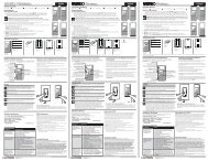
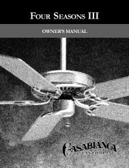
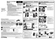
Bullet Owner’s <strong>Manual</strong>READ AND SAVE THESE INSTRUCTIONS!Safety <strong>and</strong> the proper operation of your Casablanca fan both require a thorough knowledgeof the product <strong>and</strong> proper installation; therefore, before attempting to install <strong>and</strong> operate yourCasablanca fan, read this owner’s manual completely <strong>and</strong> carefully. Retain this manual forfuture reference.CAUTION: To avoid possible electrical shock, make certain that electricity is turned offat the circuit breaker or fuse box before attempting any installation procedure.CONTENTSParts Guide .............................................................................................................................. 2Introduction________________________________________________________________________5Before You Start................................................................................................................................................. 5Safe Use............................................................................................................................................................. 5Mounting Recommendations........................................................................................................................... 6Sloped Ceiling Installation................................................................................................................................ 6Fan Installation_____________________________________________________________________7Getting Started.................................................................................................................................................. 7Canopy Installation........................................................................................................................................... 8Fan Preparation................................................................................................................................................. 9Hanging the Fan...............................................................................................................................................11Wiring................................................................................................................................................................12Securing the Canopy........................................................................................................................................13Blade Installation..............................................................................................................................................14Light Kit installation.........................................................................................................................................15lIGHT bULB iNSTALLATION............................................................................................................................16W-74 Wall Control Preparation........................................................................................................................18W-74 Control Installation__________________________________________________________ 19Installing the W-74 Wall Control......................................................................................................................19Single W-74 Installation...................................................................................................................................19Dual W-74 Installation..................................................................................................................................... 20W-74 Operation___________________________________________________________________ 21Operation Power............................................................................................................................................. 21Operation Speed Control................................................................................................................................ 21Operation Reversing Airflow.......................................................................................................................... 21Operation Lights.............................................................................................................................................. 21Changing Frequency Setting.......................................................................................................................... 22Operation CFL Mode....................................................................................................................................... 22Automatic Demonstration Program.............................................................................................................. 23Operation Safe-Exit®...................................................................................................................................... 23Light-minder® Program.................................................................................................................................. 23Operation Fan-Minder Program................................................................................................................. 24Operation Home-Safe® Program.................................................................................................................. 24Troubleshooting Tips______________________________________________________________ 25Care Recommendations___________________________________________________________ 26Product Specifications____________________________________________________________ 26P/N C4343001RL0110
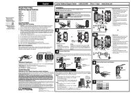
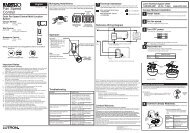
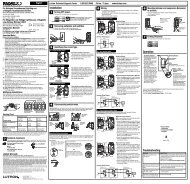
BulletModel # C43G45L C43G546LAsm. Dwg. # 99931-01 99931-02Finish Brushed Nickel Brushed CocoaQnty Part #Part # Part #1 G0903-01-214 G0903-01-546111111112 13162221 89346-01-000 89346-01-000331 77745-02-214 77745-02-5461 77745-21-214 77745-21-5461 G0544-01-214 G0544-01-5464 99934-04-232 99934-04-2321 G0111-10-000 G0111-10-0001 G0113-52-000 G0113-52-0001 89440-39-000 89440-39-000991 89653-01-000 89653-01-0001 G0548-01-000 G0548-01-000211 65350-01-000 65350-01-0001 67257-01-000 67257-01-0001 89654-01-000 89654-02-0001 89350-01-000 89350-01-000114221 G0667-01-000 G0667-02-000313321 65520-02-000 65520-02-000Call our Support Center toll free at 1-888-227-217814152024222330 31 32 33 3413
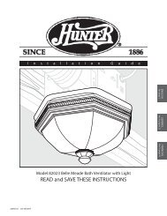
PLEASE INSPECT ALL PACKAGING PRIOR TO DISCARDING!Your Casablanca fan was crafted with pride <strong>and</strong> care <strong>and</strong> inspected thoroughly prior toshipment. Before you begin to assemble <strong>and</strong> install your Casablanca fan, remove allparts from the carton <strong>and</strong> check them against the Parts Guide in this manual.Make sure all parts are included in the box using the Parts Guide on the following pages.If there are missing or broken parts:Call 1-888-227-2178 Monday through Friday, 8 a.m.to 5 p.m. Central. Your request will be h<strong>and</strong>ledimmediately. Replacement parts will be sent to youvia Federal Express.Proper Parts H<strong>and</strong>lingDo not remove light bulbs from their packaginguntil you are ready to install them.Before discarding packaging materials, be certainthat all parts have been removed.Use a clean, dry paintbrush to remove smallStyrofoam pieces that may remain after unpacking.Do not brush Styrofoam into wiring cavities.The blades in each pack are matched for equalweight to assure smooth fan operation. If morethan one fan is being installed, do not mix bladesfrom different cartons.When cleaning, painting, or working near your fan,be cautious of the fan <strong>and</strong> blades.Always turn power to the ceiling fan OFF beforereplacing light bulbs or working on your fan.Never insert anything into the path of the fanblades while the fan is in operation.Never install a fan over a pool or spa.Never operate a fan that has been damaged in anyway.Install the fan according to the instructions in thismanual.If the fan does not work:Refer to the Troubleshooting Tips in this Owner’s<strong>Manual</strong>.Call Technical Support at 1-888-227-2178.Contact your local Authorized Service Center.Our Web site at www.casablancafanco.comcontains additional information on Casablancaproducts, troubleshooting, <strong>and</strong> Authorized Dealeror Service Centers. Please do not return thisproduct to the store.RECORD MODEL AND SERIAL NUMBERS BEFORE INSTALLATION!Please take a moment to locate the model number <strong>and</strong> serial number from your fan (see below) <strong>and</strong> recordthis information on the Warranty page inside the front cover of your Owner’s <strong>Manual</strong> if it does not appearthere already. These numbers are found on the motor identification plate affixed to the fan motor in thelocation shown below:Motor Identification PlateMemphis, TNTYPEHANGER TYPEDJ01 1151 MODEL C43GxxxLSERIAL No.: DJ06 2237C43GxxxLSerial NumberModel Number4
INTRODUCTIONBEFORE YOU STARTBullet• CAUTION: RISK OF ELECTRICAL SHOCK! Installation is to be in accordance with the National ElectricalCode, ANSI/NFPA 70-1999 <strong>and</strong> local codes. If you are unfamiliar with the wiring codes, you should usea qualified electrician.• This fan is designed to be installed on an existing electrical outlet box. The outlet box must be UL Listedfor ceiling fan installations. If it is not, a new box must be installed. Casablanca extension poles areavailable for sloped or high ceiling installations.• This ceiling fan requires a grounded electrical supply of 120 VAC, 60 Hz <strong>and</strong> a minimum 15 amp circuit.The maximum current requirement for the fan with light fixture is 2 amps. The fan uses about 1 amp or100 watts. Maximum light current is 1amp or 120 watts of lighting.• Where wire nuts are employed, be sure all bare wires are within the connectors. When installing thecanopy, make sure all wires are within the canopy <strong>and</strong> that no wires are being pinched.WARNING: Do not bend the blade brackets when installing the brackets, balancing the blades, orcleaning the fan. Do not insert foreign objects in between the rotating fan blades.UnpackingBefore assembling <strong>and</strong> installing your ceiling fan, remove all parts from the shipping cartons <strong>and</strong> checkthem against the parts listed in the Parts Guide. Before discarding packaging materials, be certain that allparts have been removed.For best performance <strong>and</strong> for your warranty to be valid, use only genuine Casablanca blades, lightfixtures, <strong>and</strong> accessories.SAFE USE• The blades in each pack are matched for equalweight to assure smooth fan operation. If morethan one fan is being installed, be careful not tomix blades from different cartons.• It is always a good idea to have an assistant tohelp with the installation.• Always turn the power OFF to the ceiling fanbefore working on it or replacing light bulbs.Fuse Box(Remove fuse for thecircuit you will beworking on)Circuit Breaker(Trip breaker for thecircuit you will beworking on)18"70"84"5
MOUNTING RECOMMENDATIONSBefore mounting your Casablanca fan, read the following helpful recommendations. The location of thefan, air circulation, <strong>and</strong> fan size are all important factors to consider before installation.LocationCeiling fans have practical uses in almost every roomin your home. We suggest you follow these mountingrecommendations as you decide where to install yourCasablanca fan.• For safety reasons, the fan blades must be a minimum of 7'above the floor.• Do not locate the fan in a doorway or above a swinging door.• In bedrooms, fans work best when mounted above the foot ofthe bed.• Over pool tables, be sure to provide plenty of clearance to avoiddamage from pool cues.• In kitchens be sure to allow for open cupboard doors to clearthe fan blades.• Do not install a fan close to or over a pool or spa. High humidity combined with corrosive gases willdestroy the finish <strong>and</strong> warp the blades.Fan SizeVariable fan speed capability permits the use of a full-size 52" fan even in smaller rooms. For very largerooms, two fans may be needed.Suggested Extension Pole LengthsCeiling HeightPole Length8' 0" 4.5"8' 6" 4.5"9' 0" 12"9' 6" 12"10' 0" 18"11' 0" 24"12' 0" 36"13' 0" 48"14' 0" 60"SLOPED CEILING INSTALLATIONExtensionPoleMaximum ®angle 32º7' minimumBlades must be aminimum of 7 feetabove the floorWhen to Use Extension PolesFor optimum performance <strong>and</strong> appearance,an extension pole should be used with yourCasablanca fan when installing on high (cathedral)ceilings or sloped ceilings. Casablanca offersst<strong>and</strong>ard poles in increments of 6" up to 5'. Custompoles are available in lengths up to 9'9". See yourAuthorized Casablanca Dealer for details.Note: Fan may wobble or vibrate if pole length isnot long enough <strong>and</strong> inside blade is too close todownslope or side wall. Extending pole length willusually solve problem.Calculation of Ceiling AngleUse the tear-off Ceiling Angle Template card insertedin this manual. It provides you with a simple “go”or “no-go” for installing your fan on a slopedceiling.6EXAMPLE 1EXAMPLE 2EXAMPLE 3This slope is less than 32º.It is OK to install your fan.This slope is 32º. This is the maximumslope that will allow the fan to hangstraight down. It is OK to install yourfan.This slope is more than 32º. Your fan willnot hang straight down, an adaptor isnecessary. Contact your local AuthorizedCasablanca Dealer in regards to purchasinga “Sloped Ceiling Adaptor.”
Installing a New Ceiling Fixture Outlet BoxIf you do not have an existing fixture locatedwhere you wish to place your Casablanca fan,an approved ceiling fixture outlet box must beinstalled <strong>and</strong> wired.WARNING!To reduce the risk of fire, electrical shock, orpersonal injury, mount to outlet box marked“Acceptable Fan Support of 22.7 kg (50lbs.) or less” using the mounting hardwareprovided with the outlet box or directly tostructure.FAN INSTALLATIONGETTING STARTEDBulletUsing Existing Ceiling Fixture Outlet BoxAfter turning the power OFF at its source (eitherthe circuit breaker or fuse box), lower the oldfixture <strong>and</strong> disconnect the wiring. Check theceiling fixture outlet box to be sure it is marked“Approved for Ceiling Fan Mounting.” If it is not,a new box must be installed.Note: The weight of this fan is 29 pounds.NOTE: Lag Screw installation is required only under two conditions:• Fan weighs 36 lbs. or more• If the existing ceiling fixture outlet box needs to be modified for a ceiling fan application (forexample, if the house is not new construction <strong>and</strong> you are replacing an existing light fixture).We recommend that the ceiling box be of sufficient capacity to support the weight of the fan <strong>and</strong> lightfixture under any conditions. If in doubt whether you need to install the lag screw, consult a qualifiedelectrician.CEILING HARDWARE (not to scale)LAG SCREW INSTALLATIONCeiling PlateLag Screw <strong>and</strong> Washer (1)1" x 8-32 Round head Screw <strong>and</strong>Washer (2)Note: After removing the old fixture, check theoutlet box to insure that it is supported by a joistor beam across its upper surface. If not, a 2 x4stud must be installed.Step 1. Remove the knockout plug in the center of theoutlet box or drill a 1 /2-inch hole for the lag screw to passthrough. Then drill a 1 /4-inch guide hole into the joist orbeam to a depth of 3 inches.Step 2. Thread the lead wires from the outlet boxdown through the large hole in the ceiling plate.Step 3. Align the slotted holes in the ceiling platewith the screw holes in the outlet box.Note: The isolators should be flush against the ceiling.7
MOUNTING BRACKET INSTALLATION (CONT.)Step 1. Place a flat washer on each of the twoscrews that came with the outlet box <strong>and</strong> pass thescrews through the slotted holes in the ceiling plateinto the screw holes in the outlet box.Step 2. Tighten the screws into the outlet box;do not use lubricants on the screws. Do not overtighten.Step 3. Install the lag screw if needed pass the lagscrew with the large washer attached through thecenter hole of the ceiling plate <strong>and</strong> screw into theguide hole. Tighten until the outlet box is mountedfirmly to the beam. This box must be secured to theceiling firmly.WasherOutletBoxScrewCeiling FanApprovedWiring BoxCeiling FanApprovedWiring BoxWasherLag BoltOutletBoxScrewCANOPY HARDWARECanopy Screws (2)CanopyCANOPY INSTALLATIONStep 1. Attach the canopy to the ceiling plate byaligning the two hex-head bolts in the canopy withthe two keyhole slots in the ceiling plate. Place thetwo hex-head bolts into the two keyhole slots onthe ceiling plate <strong>and</strong> rotate clockwise until canopyis engaged to ceiling plate.Keyhole SlotsCeilingPlateCanopyNOTE: On sloped ceilings, align the canopyopening with the top or peak of the room.Hex-head Bolts8
BulletStep 2. Instal two canopy screws into the ceilingplate. Tighten using the provided screwdriver untilsnug against the ceiling.CeilingPlateCanopyCanopy ScrewsPrepare for fan installation as follows:Step 1. Remove the paper shield from the motoras shown in Figure #1.Step 2. Loosen the Set Screw making sure thatend of the Set Screw can not be seen within themotor coupling as shown in Figure #2. If so, youwill need to unscrew the Set Screw so that the tipof the Set Screw does not remain in the path of thedownrod.Step 3. Slide both the hanging adapter cover <strong>and</strong>canopy cover ring on to the downrod, then routethe wires through the 3.5" Perma•Lock downrod<strong>and</strong> ball assembly as shown in Figures #3. Insertthe downrod into the motor coupling <strong>and</strong> turn itclockwise until it stops turning, ensuring that thedownrod has bottomed out.FAN PREPARATIONPAPER MOTORSHIELDFIGURE 1.Set ScrewStep 1. Feed the wires from the top of the fanthrough the Downrod Cover <strong>and</strong> the downrodNote: Make sure all the wires are on the same sideof the metal dowel pin inside the downrod.9' CEILING INSTALLATIONFIGURE 2.DownrodStep 2. Twist the downrod into the Motor AdapterCAUTION: The Motor Adapter has a specialcoating on the threads. Do not remove thiscoating; the coating prevents the downrodfrom unscrewing. Once assembled, do notremove the downrod.DownrodCover9
Step 3. Securely retighten the setscrew on theMotor Adapter.Step 4. Assemble Downrod cover to top of themotor using (3) #6-32 .38" Downrod cover screws.DownrodCoverSetscrewCAUTION: Failure to fullylock in the downrod beforesecurely tightening the setscrew may cause the fan toseparate from the downrod<strong>and</strong> fall during normaloperation.DownrodDownrodCoverDownrodCover Screw8' CEILING INSTALLATIONStep 1. Feed the wires from the top of the fanthrough the downrodNote: Make sure all the wires are on the same sideof the metal dowel pin inside the downrod.DownrodStep 2. Twist the downrod into the Motor AdapterCAUTION: The Motor Adapter has a specialcoating on the threads. Do not remove thiscoating; the coating prevents the downrodfrom unscrewing. Once assembled, do notremove the downrod.Step 3. Securely retighten the setscrew on theMotor Adapter.SetscrewCAUTION: Failure to fullylock in the downrod beforesecurely tightening the setscrew may cause the fan toseparate from the downrod<strong>and</strong> fall during normaloperation.10
Step 1. To hang the fan body in the canopy,hold the fan body firmly <strong>and</strong> insert the ball intothe canopy opening as in Figure #1. Check that nowires are pinched. Rotate the fan body until theslot in the ball fits into the pin opposite the canopyopening in Figure #2.HANGING THE FANBulletSlotFIGURE 1.PinFIGURE 2.11
WIRING HARDWAREReceiver Blue Wire Caps (3) Orange Wire Caps (3)WIRINGStep 1. Locate the White wire marked "NEUTRALIN" <strong>and</strong> connect it to the White Neutral Wire fromyour ceiling using one of the supplied orange wirecaps.Step 2. Connect the Black wire marked "POWER IN<strong>and</strong> the Black Power Wire from your ceiling with anorange wire cap.WhiteNeutral FromCeilingPower FromCeilingCanopyHatchLine Power(IN)Line Neutral(IN)Step 3. Tuck the White <strong>and</strong> Black connected wiresback into the canopy while you slide the Receiverinto the open end of the canopy as shown.NOTE: Ensure you do not tuck the bare groundwire from the ceiling back into the box. This will beconnected later.Bare GroundWireTuck Wiresin BoxStep 4. Connect the (Down Light) Blue wiremarked LIGHT 1 OUT from the Receiver to the BlueWire coming from the fan with a blue wire cap.Blue -DownlightPower12
Step 5. Connect the White wire marked NEUTRALOUT from the receiver <strong>and</strong> connect it to the WhiteWire coming from the fan with a blue wire cap.Step 6. Use the Red wire marked FAN OUT fromthe receiver <strong>and</strong> connect it to the Red Wire comingfrom the fan with a blue wire cap.White-Neutralto FanBulletRed-Powerto FanGreen fromMounting PlateStep 7. Connect the Green wire from theMounting Plate, Bare Wire from the ceiling, <strong>and</strong>the Green Wire from the downrod assembly <strong>and</strong>connect them together with an orange wire cap.Green fromFanBare fromCeilingStep 1. Carefully tuck the wires into the canopyaround the Receiver as not to loosen the wire caps.Step 2. Insert Canopy Door at an angle as shownin Figure 1.SECURING THE CANOPYStep 3. Swing Canopy Door up until it is secure tothe Canopy. See Figure 2.FIGURE 1. FIGURE 213
BLADE HARDWAREBlades (4)BladeGrommet (9)BLADE INSTALLATIONBlade AssemblyScrews (9)Step 1. Slide the end of the blade with the twoholes into the slot located on the blade ring asshown in Figure 1.BladeBlade RingFIGURE 1.Step 2. Using the two blade grommets <strong>and</strong> bladeassembly screws, attach the blade to the blade ringby inserting a grommet then a blade assemble screwinto the blade as shown in Figure 2.Step 3. Tighten screws by h<strong>and</strong> onlyBladeGrommetCAUTION:Blade screws must betightened securely beforeoperating the fan.Blade AssemblyScrewsBlade RingFIGURE 2.Step 4. Repeat for each blade assembly untilall four blades have been installed on the fan asshown in Figure 3.14FIGURE 3.
LIGHT KIT HARDWAREBulletLight Kit FitterLight Kit FitterScrews (3)Lamp AssemblyLIGHT KIT INSTALLATIONLamp AssemblyScrews (3)Ceramic WireNuts (2)Step 1. Attach the Light Kit Fitter to the fittermounting plate using (3) Light Kit Fitter Screws.FitterMountingPlateLight KitFitterLightKit FitterScrewsFIGURE 1.Step 2. Wire Lamp Assembly to fan using theprovided ceramic wire nuts.Step 3. Attach the Lamp Assembly to the Light KitFitter using (3) Lamp Assembly Screws.LampAssemblyLight KitFitterLamp AssemblyScrewsFIGURE 2.15
LIGHT BULB HARDWARE100W Halogen BulbLIGHT BULB INSTALLATIONGlass ShieldStep 1. Install the 100W halogen bulb by insertingit into the lamp holder at an angle, then tilt the bulbupward until it fits in the other side. See Figure1.Lamp HolderWhen installing the halogen bulb, carefully cutoff the end of the plastic sleeve the bulb comesin <strong>and</strong> hold the bulb by the plastic sleeve toscrew it into the socket.Halogen BulbFIGURE 1.WARNING: Do not touch the glass bulbs withyour fingers. It is extremely important that theglass be clean. If it is touched, or dirty, cleancarefully with a tissue. A dirty glass bulb willcause the bulb to fail almost immediately.GlassShieldStep 2. Install the glass shield by pushing it intoplace with the clips on the light sockets as shown inFigure 3.FIGURE 2.16FIGURE 3.
GLASS SHADEBulletGlass ShadeGLASSHOLDINGTABSStep 1. Align the glass shade up with the bottomof the fan as shown in Figure #1 <strong>and</strong> locate thethree glass holding slots. Then locate the threeglass holding tabs, located on the light fixture plateStep 2. Carefully lift the glass globe up inside thelight fixture as far as it will go. Rotate the shade in acounter clockwise direction as shown in Figure #2,until the glass globe is held tightly in place by thethree tabs.GLASSSHADEGLASSHOLDINGSLOTSFigure #1Figure #217
W-74 WALL CONTROL PREPARATIONWARNING!To avoid possible electrical shock, makecertain that electricity is turned off at thecircuit breaker or fuse box before attemptingany installation or repair procedureFuse Box(Remove fuse for thecircuit you will beworking on)Circuit Breaker(Trip breaker for thecircuit you will beworking on)CAUTION! NOT turning the power OFF at thecircuit breaker or fuse box may cause damageto the electronics within the wall control <strong>and</strong> orthe PC board on the fan.18
W-74 CONTROL INSTALLATIONINSTALLING THE W-74 WALL CONTROLNOTE: W-74 Wall Control should only be installed on Casablanca's Direct-Touch TM <strong>Fans</strong>.Direct - TouchThe wall control installs in the same manner as an ordinary light switch, using an existing wall box <strong>and</strong>wiring. This controller is designed to signal the fan microcomputer as well as perform normal switchingoperations. For this reason the following precautions must be observed:1. Use only the Casablanca W-74 wall control.2. Do not use any additional control with yourDirect-Touch TM fan (for example, dimmer, or fanspeed control).SINGLE W-74 INSTALLATION3. Do not use more than one fan per wall control.4. No other light fixtures or electrical appliancesmay be connected on the circuit controlled by theW-74 wall control.CAUTION!Ensure power is turned OFF at the breaker or fuse panel before starting installation.1. If you have multiple Direct-Touch TM fans, refer to thesection "changing frequency setting" on page 20.2. Remove the screws <strong>and</strong> switch plate from the existingswitch box.3. Remove the screws holding the switch in the switchbox.4. Pull the existing switch from the switch box to exposethe wire connections.5. Remove the two wires from the switch.6. Connect the BLACK wire from the POWER SOURCEthat you just removed from the switch to the BLACK/WHITE STRIP wire on the W-74 wall control. Securethis connection with a wire nut.7. Connect the second BLACK wire that you just removedfrom the switch to the second BLACK wire on thelocated on the back of the W-74 wall control. Securethis connection with a wire nut.NOTE: The RED wire is not used in thisapplication. DO NOT remove the crimpedcap from the wire.W-742 BLACKWIRESFigure 1Black/WhiteBlueRedWhiteW-74Wall Control8. Connect the green ground wire comingfrom the back of the W-74 control to theground wire in the switch box. Securethe splice with a wire nut.9. Check your work by using the wiringdiagrams as shown in Figures # 1 <strong>and</strong> #2.10. Install the W-74 in the wall box with thetwo long screws provided.11. Install the wall plate with the two whitescrews.Figure 2RED WIRENOT USEDBLACK AND WHITESTRIPED WIRE19
DUAL W-74 INSTALLATIONTo control the fan <strong>and</strong> lights from two locations (a three-waycircuit), use two W-74 wall controls as shown in the wiring diagramin Figure #4. Before installing the two switches into the wall, placeboth switches side by side, then locate the 6 dip switches on theside of the two switches as shown in Figure #3. Then make sure thatthe dip switches are set to the same address on both switches asshown in Figure #3. When setting these dip switches you are settingthe channel number that is required to control both your fan <strong>and</strong>lights from both sides of the room. If you are installing other Direct-Touch TM 3 fans within your home you may need to reset the dipswitches on these other fans to a different channel before installingyour W-74 wall control into the wall. Please review the section onchannel changing within this part of the operation manual as shownon page #20.DIP SWITCHES120V ACBLACKCAUTION!Figure 3Ensure power is turned OFF at the breaker or fuse panel before starting installation.NEBLACK WITHWHITE STRIPEWHITEGREENW-74TRALGREENBLACKBLACKREDREDREDBLACKGREENREDBLACKBLACK WITHWHITE STRIPEW-74Figure 46. Remove the two remaining wires from the three-wayswitch. Connect the black wire of these wires to a blackwire on the W-74 control. Secure the splice with a wire nut.The remaining red wire is to be connected to the other redwire on theW-74. Secure the splice with a wire nut. Figure 57. Connect the green ground wire coming from the back of theW-74 control to the ground wire in the switch box. Securethe splice with a wire nut.8. Check your work by using the wiring diagrams as shown inFigures # 4 <strong>and</strong> #5 on this page.9. Install the W-74 in the wall box with the two long screwsprovided.10. Install the wall plate with the two short color-matchedscrews provided.11. Installation of the second W-74 control is identical. Repeatsteps 1 through 7.BLACKBLACKBLACK1. To control the fan <strong>and</strong> lights from twolocations (a three-way circuit), use two W-74wall controls.2. Remove the screws <strong>and</strong> switch plate from theexisting switch box <strong>and</strong> the screws holdingthe switch in the switch box. Figure #53. Pull the existing switch from the switch box toexpose the wire connections.4. Determine which wire is connected to thecommon terminal from the power source(120V AC) of the three-way switch. (Theterminal will be marked on switch).5. Remove the wire from the common terminalof the three-way switch. Connect this wire tothe remaining black/white striped wire on theW-74 control. Secure this splice with a wirenut. Figure 42 BLACKWIRESFigure 5W-74Wall Control2 RED WIRESBLACK AND WHITESTRIPED WIRE20
OPERATION CFL MODEYour fan has the ability to disable 1 the 2dimming feature to allow the use ofCFL bulbs.0To activate CFL mode:4 31. Turn the fan off by pressing thepower button.2. Allow the fan to remain off for at least 5 seconds.3. Press the power button again to restore power to the fan.4. Immediately press <strong>and</strong> hold 1 the "1" 2 <strong>and</strong> "3" buttons for at least 5 seconds. The fans lights will go to100% brightness <strong>and</strong> the dimming 0 function will be disabled.To cancel CFL mode:4 35. Turn the fan off by pressing thepower button.6. Allow the fan to remain off for at least 5 seconds.7. Press the power button again to restore power to the fan.CHANGING FREQUENCY SETTINGCaution: CFL bulbs will notfunction properly whendimmed, which may resultin flickering or reduced bulblife.8. Immediately press <strong>and</strong> hold the "2" <strong>and</strong> "4" buttons for at least 5 seconds. The fans lights will dim to50% brightness <strong>and</strong> the dimming function will be enabled. Press <strong>and</strong> hold the light buttons until thedesired dimmer setting is reached.NOTE: All fans leave the factory set to“111111”DIPSWITCHESYou will only have to change the dip switch settings in the remote if youare using more than one fan in the same area <strong>and</strong> want to control themseparately.NOTE: DO NOT set dip switch setting in theremote to ‘0000’, this may cause frequencyinterference from other Casablanca Products.DIP SWITCHESSET TO ‘111111’(Factory Setting)(Figure 1)1. Turn power OFF at the circuit breaker or fuse box <strong>and</strong> at the toggleswitch, for the fan you want to change.2. Remove the screws <strong>and</strong> switch plate from the existing switch box.3. Remove the screws holding the switch in the switch box.4. Pull the existing W-74 switch from the switch box to expose the dipswitches located on the side of the control as shown in Figure #1.5. Change the dip switch settings, assuring that they are different fromthe previously installed Direct-Touch fan.6. Mount the W-74 Wall Control unit back into the wall 1 electrical 2 box.7. At the circuit breaker or fuse box <strong>and</strong> at the toggle switch, 0 turn thepower off for the fan whose frequency you are 4changing.38. Within 20 seconds of restoring power to the ceiling fan <strong>and</strong> the W-74Wall Control press <strong>and</strong> hold both the “1” <strong>and</strong> reverse buttonsas shown in Figure #2. For 3 seconds, you will hear one tone fromthe Piezo Buzzer indicating the comm<strong>and</strong> has been accepted. The Fan<strong>and</strong> Lights will be off.22DIP SWITCHESSET TO ‘000000’(Figure 2)
Direct - TouchAUTOMATIC DEMONSTRATION PROGRAMProgrammed into every Direct-Touch fan is an Automatic DemonstrationProgram. 1 It can 2 be used to fully demonstrate <strong>and</strong> test the operation of thefan. 041 32To enter the demonstration program:01. Turn the power button off for at least 5 seconds. This will clear4 3the fan memory ready for programming.2. Turn thepower button on.3. Immediately hold the "0" button for at least 5 seconds.A multi-tone signal will verify the start of the test program. The fan <strong>and</strong>1 2lights will go through a series of changing fan speeds, reversing the fanoperation mode, 0 turning off/on, <strong>and</strong> dimming the lights.4 3The complete cycle lasts slightly over one minute. It will continue torepeat until the is turned off for more than five seconds, cancellingthe program.1 2OPERATION SAFE-EXIT®The Safe-Exit 0 Program gives you about thirty seconds of light when you turn thelights off, 4 enabling 3 you to exit your home before the lights go out. To enter the Safe-Exit Program:1. Press the power button off for at least five seconds.Safe-Exit2. Turn the Power on. Immediately press <strong>and</strong> hold the "4" button for 5 seconds.When a light button is pressed, an audio tone <strong>and</strong> series of lights blinking will indicate the program1 2is active. When CFL mode is disabled, the Lights will stay on at 50% brightness for 20 seconds thendecrease in intensity for 30 seconds then 0turn off.4 33. With CFL mode active, the lights will turn off after 30 seconds.4. To cancel the Safe-Exit Program, press the1 2The Light-Minder Program automatically turns OFF the fan mounted 0 lights after twohours. To 1 enter 2the Light-Minder Program:4 301. To operate the lights for Light Minder Program – Turn the4 3for at least 5 seconds.power button off2. Turn the on. Immediately press <strong>and</strong> hold the "1" button for 5 seconds. Aseries of tones will be heard through the piezo-buzzer indicating the comm<strong>and</strong>has been accepted. Once the lights turn on, they will automatically turn off after2 hours.Light-Minder3. Light operation still remains normal, if you 1 leave 2the room <strong>and</strong> turn OFF thelights, the lights will blink to indicate the Light 0 Minder comm<strong>and</strong> has beenaccepted. The lights will stay on for 2 hours <strong>and</strong> then begin to dim. After thirty seconds have elapsed,4 3the lights will turn completely off. In CFL Mode, the lights will not dim, but shut off after 2 hours.4. To cancel the Light Minder Program, press thepower button <strong>and</strong> leave off for five seconds.LIGHT-MINDER® PROGRAMNote: With CFL mode active,the lights will not dim.power button <strong>and</strong> leave off for five seconds.23
1 21 201. To operate the Home-Safe Program – Turn the4 3least 5 seconds.0OPERATION 4 HOME-SAFE® 3PROGRAMpower button off for at2. Turn the on. Immediately press <strong>and</strong> hold the "3" button for 5 seconds.A series of tones will be heard through the piezo-buzzer indicating thecomm<strong>and</strong> has been accepted.Note: This program overrides all manual control of lights <strong>and</strong> fan.3. The lights will automatically cycled on <strong>and</strong> 1 off in 2a controlled sequence asfollows: ON 1 hour, OFF ½ hour, ON 2 hours, 0OFF 1 hour, ON ½ hour thenOFF 2 hours. This seven hour pattern will repeat continuously so that a4 3different pattern of lighting is seen each day of the week.4. 4) To cancel the Home-Safe Program, press theseconds.Button OFF for fiveOPERATION FAN-MINDER PROGRAM1 2The Fan-Minder feature will add to your comfort when used in 0the bedroom. The programreduces 1the speed 2 of the fan each two-hour interval to compensate 4 3 for cooling night air.01. To operate the lights for Light Minder Program – Turn the4 3at least 5 seconds.power button off for2. Turn the on. Immediately press <strong>and</strong> hold the "2" button for 5 seconds. Aseries of tones will be heard through the piezo-buzzer indicating the comm<strong>and</strong>has been accepted. Once the lights turn on, they will automatically turn off after 2hours.3. The fan will respond with three descending tones. A timer is now initiated <strong>and</strong> the fanwill reduce one speed for each two-hour1interval.2The fan will not, however, descendbelow the first or the lowest speed.04. You may increase the fan speed by pressing <strong>and</strong> holding any of the fan speed buttons until the desired4 3speed is reached, then release it. The fan will again reduce one speed for each 2 hour interval.5. To cancel the Fan-Minder Program, turn theOFF for 5 seconds.24
TROUBLESHOOTING TIPSBulletPlease refer to this troubleshooting guide before requesting service or contacting your dealer for assistance.PROBLEMPOSSIBLE REMEDIESFan will not start• Check the main circuit fuses, circuit breakers, <strong>and</strong> wall switch position. Check all wire connections.Make sure the power 1 is turned 2 off during this inspection.• Pin connectors are not making good contact. Check all connections.0• The fan receiver is defective. Replace the fan receiver.• Reset the frequency 4 setting: 3 Turn the power off at the circuit breaker for the fan that is not functioningonly. Within 20 seconds from restoring power to the ceiling fan <strong>and</strong> the W-74 Wall Control press <strong>and</strong> holdboth the “1” <strong>and</strong> reverse buttons as shown in Figure #2 for 3 seconds, you will hear one tone fromthe Piezo Buzzer indicating the comm<strong>and</strong> has been accepted. The Fan will come on at “low” speed in thereverse direction.Fan wobbles or shakes excessively• Be sure the canopy pin is set properly into the slot on the ball.• Check that the blade holders have not been bent during installation <strong>and</strong> the blades are balanced.• The hanger bracket <strong>and</strong>/or the ceiling outlet are attached too loosely. Make sure the hanger bracket isattached tightly to the ceiling outlet box <strong>and</strong> the downrod assembly is secured firmly.• The downrod is attached to the downrod base too loosely. Make sure all the screws are securelytightened.• A balancing kit is supplied with the fan to remedy slight wobble problems. Check all previous stepsbefore using this kit.Fan is noisy during operation• When changing fan speeds or reversing the fan, you may hear several audible clicks. This is normaloperation.• Check <strong>and</strong> tighten the light fixture retaining screws, glass shade screws, <strong>and</strong>/or lightbulb(s).• Tighten the canopy screws <strong>and</strong> mounting plate assembly. Make sure the wire nuts inside the canopy<strong>and</strong> switch housing are not touching the metal parts <strong>and</strong> that they have not fallen off the wire splices.Tighten as necessary.• Tighten the blade holders to the flywheel (or Direct Drive motor) <strong>and</strong> the blades to the bladeholderscrews.• Make sure all the screws in the motor housing are snug but not overly tight.Fan does not run on low speed• If fan is new, it may need to be “broken in.” Run at high speed for several days.Light is too dim• Make sure the dimmer setting is at the desired level.Hold the light button to activate the dimmer ofthe light. Release the button when the desired luminosity is reached.This device complies with RSS-210 of Industry Canada. Operation is subject to the following two conditions: (1) this1 2device may not cause interference, <strong>and</strong> (2) this device must accept any interference, including interference that maycause undesired operation of the device.01. This device complies with part 15 of the FCC Rules. Operation is subject 4 3to the following two conditions: (1) thisdevice may not cause harmful interference, <strong>and</strong> (2) this device must accept any interference received, includinginterference that may cause undesired operation.2. This equipment has been tested <strong>and</strong> found to comply with the limits for a Class B digital device, pursuant to Part15 of the FCC Rules. These limits are designed to provide reasonable protection against harmful interference in aresidential installation. This equipment generates, uses <strong>and</strong> can radiate radio frequency energy <strong>and</strong>, if not installed<strong>and</strong> used in accordance with the instructions, may cause harmful interference to radio communications. Howeverthere is no guarantee that interference will not occur in a particular installation. If this equipment does causeharmful interference to radio or television reception, which can be determined by turning the equipment off <strong>and</strong>on, the user is encouraged to try to correct the interference by one or more of the following measures: Reorientor relocate the receiving antenna, Increase the separation between the equipment <strong>and</strong> receiver, Connect theequipment into an outlet on a circuit different from that to which the receiver is connected. Consult the dealer oran experienced radio/TV technician for help. Note: Any changes or modifications to the transmitter or receiver notexpressly approved by Casablanca Fan Company may void one’s authority to operate this remote control.25
Fan Finishes• For cleaning, a soft brush or lint-free cloth should be used to prevent scratching the finish.• A vacuum cleaner brush nozzle can remove heavier dust.• Surface smudges or an accumulation of dirt <strong>and</strong> dust can be removed easily using a mild detergent <strong>and</strong>slightly dampened soft cloth. An antistatic agent may be used, but never use abrasive cleaning agents asthese will damage the finish.Blades• Wood-finish blades should be cleaned with a furniture polishing cloth. Occasionally, a light coat offurniture polish may be applied for added protection <strong>and</strong> beauty.• For painted <strong>and</strong> high-gloss blades, surface smudges or an accumulation of dirt <strong>and</strong> dust can be removedeasily using a mild detergent <strong>and</strong> slightly dampened soft cloth. An antistatic agent may be used, but neveruse abrasive cleaning agents as these will damage the finish.No Need for Lubrication• Never lubricate this fan! The precision motor at the heart of your Casablanca fan features sealed bearingsthat are lubricated for life.• Do not attempt to oil the motor.Changing Light bulbsModel Name: BulletModel Number: C43GxxxLDimensions: A = 21.2B = 24.8C = 3.1D = 8.1E = 7.0Weight: 29 lbs.CARE RECOMMENDATIONS• Be sure to turn the power to OFF at the wall switch or circuit breaker before changing light bulbs.• Replace bulbs with the same type as you removed from the light fixture.• The maximum wattage rating for this fan’s light kit is 120 watts.FOR QUESTIONS OR TO LOCATE THE NEAREST CASABLANCA AUTHORIZEDSERVICE CENTER CALL TOLL FREE: 1-888-227-2178OR VISIT US ON THE WEB AT: WWW.CASABLANCAFANCO.COMPRODUCT SPECIFICATIONSMotor: 172mm x 20mm Direct DriveBlade Span With: 54"Blade Pitch: 14°No. of Blades: 4Airflow: 5,983 cfmElectricity Use: 68.4 wattsAirflow Efficiency: 87.5 cfm/watt26