Kalzip Installation Guideline
Kalzip Installation Guideline
Kalzip Installation Guideline

You also want an ePaper? Increase the reach of your titles
YUMPU automatically turns print PDFs into web optimized ePapers that Google loves.
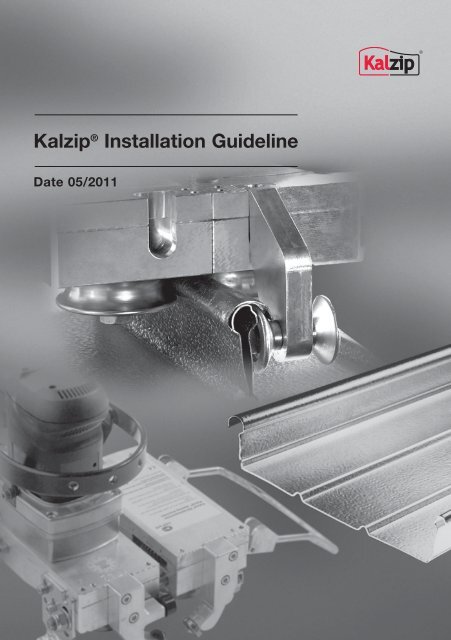
<strong>Kalzip</strong> ® <strong>Installation</strong> <strong>Guideline</strong><br />
Date 05/2011
Introduction<br />
Introduction<br />
This <strong>Kalzip</strong> <strong>Installation</strong> <strong>Guideline</strong> provides<br />
the company with the "<strong>Installation</strong><br />
Instructions" required by the building regulations<br />
for installing the profiled sheets.<br />
It provides information, general notes and<br />
explanations, as well as detailed instructions<br />
for installing <strong>Kalzip</strong> aluminium roof<br />
and wall systems.<br />
The present <strong>Guideline</strong> provides a basis<br />
for the correct, professional installation<br />
of <strong>Kalzip</strong> profiled sheets. It deals with<br />
the usual cases of processing and use.<br />
Supplementary guidelines are available<br />
for special applications, such as the<br />
installation of <strong>Kalzip</strong> solar power systems<br />
or the inclusion of roof lights (see<br />
www.<strong>Kalzip</strong>.com/<strong>Installation</strong>.de).<br />
The <strong>Kalzip</strong> <strong>Installation</strong> <strong>Guideline</strong> constitutes<br />
part of a quality concept comprising<br />
the technical rules for installation in lightweight<br />
metal construction (Fachregeln des<br />
Metallleichtbaus – Montage) published by<br />
the IFBS (Industrieverband für Bausysteme<br />
im Metallleichtbau, a German industrial<br />
association for the lightweight metal construction<br />
sector) and the ALZ (Aluminium-<br />
Zentrale e.V.) leaflet A 7 ("Richtlinie für<br />
die Verlegung von Aluminium-Profiltafeln"),<br />
which provides a guideline for the installation<br />
of aluminium profiled sheets.<br />
The applicable building authorities regulations,<br />
standards, accident prevention<br />
regulations, rules for health and safety<br />
and other similar guidelines have been<br />
taken into account.<br />
The images and processing descriptions<br />
included here represent the present state<br />
of the technology. They do not take into<br />
account any specific application. We<br />
re serve the right to make technically<br />
appropriate modifications to the designs<br />
or installation procedures for the sake of<br />
our high quality standards and of progress.<br />
Due to the dynamism of product developments<br />
and improvements, the <strong>Kalzip</strong><br />
printed documents do not always correspond<br />
to the actual products. The currently<br />
valid version of the <strong>Installation</strong> <strong>Guideline</strong><br />
can be downloaded from the Internet at<br />
www.kalzip.com.<br />
In the event of disagreement between<br />
those responsible for the construction,<br />
this <strong>Guideline</strong> shall be the standard for<br />
the correct and professional method for<br />
installing <strong>Kalzip</strong>.<br />
The fact that this <strong>Guideline</strong> has been<br />
released does not obviate the personal<br />
responsibility of those concerned for their<br />
actions. Moreover, <strong>Kalzip</strong> GmbH cannot<br />
accept liability for any errors that this<br />
<strong>Guideline</strong> may contain. In the light of<br />
present knowledge it does nevertheless<br />
ensure correct technical performance.<br />
Compensation claims cannot be based<br />
on its application.<br />
March 2011<br />
Copyright <strong>Kalzip</strong> GmbH
Overview of contents<br />
Introduction 1.0<br />
The System 2.0<br />
Transport · Storage · Inspection 3.0<br />
Clip installation 4.0<br />
Installing <strong>Kalzip</strong> · renovating with <strong>Kalzip</strong> 5.0<br />
Connections 6.0<br />
<strong>Installation</strong>s 7.0<br />
Welding · cutting · bending 8.0<br />
Useful hints and advice 9.0<br />
Special tools 10.0<br />
System components and accessories 11.0
Contents<br />
Overview Page<br />
1.0 Introduction<br />
1.0 Introduction 8<br />
2.0 The System<br />
2.0 The System 9<br />
2.1 <strong>Kalzip</strong> range of applications 10<br />
2.1.1 <strong>Kalzip</strong> non-ventilated roof on trapezoidal steel deck 11<br />
2.1.2 <strong>Kalzip</strong> non-ventilated roof on purlin with trapezoidal sheets inner skin 11<br />
2.1.3 <strong>Kalzip</strong> non-ventilated roof on timber rafters with visible timber lining 12<br />
2.1.4 <strong>Kalzip</strong> ventilated roof with common rafter insulation 12<br />
2.2 <strong>Kalzip</strong> DuoPlus ® 100 and <strong>Kalzip</strong> Duo ® 100 13<br />
2.2.1 <strong>Kalzip</strong> DuoPlus 100 13<br />
2.2.2 <strong>Kalzip</strong> Duo 100 14<br />
2.2.3 <strong>Kalzip</strong> DuoPlus 100 or <strong>Kalzip</strong> Duo 100 on steel trapezoidal deck 15<br />
2.2.4 <strong>Kalzip</strong> DuoPlus 100 or <strong>Kalzip</strong> Duo 100 on timber 16<br />
2.2.5 <strong>Kalzip</strong> DuoPlus 100 or <strong>Kalzip</strong> Duo 100 on concrete 17<br />
2.2.6 <strong>Kalzip</strong> DuoPlus 100 or <strong>Kalzip</strong> Duo 100 on aerated concrete 18<br />
2.3 <strong>Kalzip</strong> NatureRoof 19<br />
2.4 <strong>Kalzip</strong> FOAMGLAS ® System as a standard and combined solution 20<br />
2.5 <strong>Kalzip</strong> AF 21<br />
2.5.1 <strong>Kalzip</strong> AF with ProDach-insulation on trapezoidal steel deck 21<br />
2.5.2 <strong>Kalzip</strong> AF with ProDach-insulation on timber rafters with formwork 22<br />
2.5.3 <strong>Kalzip</strong> AF with common rafter insulation 22<br />
2.5.4 <strong>Kalzip</strong> AF on FOAMGLAS ® insulation 22<br />
3.0 Transport · Storage · Inspection<br />
3.1 Transporting to the building site or unloading at a designated area 23<br />
3.2 Unloading on the building site 23<br />
3.3 Storage on the building site 24<br />
3.4 Checking incoming materials 24<br />
3.5 Special instructions: transport, storage and installation<br />
of <strong>Kalzip</strong> profiled sheets made from AluPlusZinc 24<br />
3.6 Noise adsorber and anti-condensation coatings 25<br />
4.0 Clip installation<br />
4.1 Attachments 26<br />
4.2 Clip positioning 31
Contents<br />
Overview Page<br />
5.0 Installing <strong>Kalzip</strong> · renovating with <strong>Kalzip</strong><br />
5.1 Wind, weather 36<br />
5.2 Positioning 37<br />
5.3 Corrosion protection 37<br />
5.4 <strong>Installation</strong> 37<br />
5.5 Fixed point design: <strong>Kalzip</strong> aluminium clip / <strong>Kalzip</strong> composite clip 38<br />
5.6 Zipping procedure 40<br />
5.7 Renovating existing roofs with <strong>Kalzip</strong> profiled sheets 42<br />
6.0 Connections<br />
6.1 Ridge 43<br />
6.1.1 Upward fold 43<br />
6.1.2 Ridge closure 43<br />
6.1.3 Closure filler 43<br />
6.1.4 Spacer section / sliding element 44<br />
6.1.5 Ridge cover plate 44<br />
6.2 Gable end 45<br />
6.2.1 Gable end channel 45<br />
6.2.2 Gable end clip 45<br />
6.2.3 Gable end support rail 46<br />
6.2.4 Gable end profile 50/65 (option) only for flat roofs 46<br />
6.2.5 Cover plate 47<br />
6.3 Eaves closure and static edge reinforcement 48<br />
6.3.1 Gutter overhang 48<br />
6.3.2 Drip angle 48<br />
6.3.3 Folding 50<br />
6.3.4 Sealing the eaves 50<br />
7.0 <strong>Installation</strong>s<br />
7.1 Skylights / smoke extractors 51<br />
7.2 Vents 52<br />
7.3 <strong>Kalzip</strong> roof anchor 52<br />
7.4 Fall arrest systems 52<br />
7.5 Walkways / steps 53<br />
7.6 Solar systems 53<br />
7.7 Seam clamps (Cable clip, Seam clip stainless steel) 53
Contents<br />
Overview Page<br />
8.0 Welding · cutting · bending<br />
8.1. TIG welding 54<br />
8.1.2 Welding preparation 54<br />
8.2 Welding backing strip 54<br />
8.3 Cutting 55<br />
8.3.1 Cutting and sawing 55<br />
8.3.2 Cut-off discs 55<br />
8.4 Folding 55<br />
9.0 Useful hints and advice<br />
9.1 <strong>Installation</strong> template for installing clips 56<br />
9.2 Preassembly of the clips on top hat profiles 56<br />
9.3 Storing long profiled sheets 56<br />
9.4 <strong>Installation</strong> with several installation groups 57<br />
9.5 Protection when drilling through U disc 57<br />
9.6 Roof projections with clip bars 58<br />
9.7 Roof projections without clip bars 59<br />
9.7.1 Requirements for installation 59<br />
9.8 Roof projections constructed from <strong>Kalzip</strong> profile sheets 60<br />
9.9 Removing dirt 61<br />
10.0 Special tools<br />
10.1 Tools and accessories 62<br />
11.0 System components and accessories<br />
<strong>Kalzip</strong> composite clip type E 63<br />
Clip bar 64<br />
Clip bar curved 64<br />
Fixed point clip bar including fastening holes 64<br />
Thermal barrier polyamide 64<br />
Rotatable clip 65<br />
Rotatable clip rail perforated 65<br />
Gable end channel 65<br />
Gable end clip 50/65 66<br />
Gable end profile 50/65 66<br />
Gable end support rail 66<br />
Sliding element 67
Contents<br />
Overview Page<br />
11.0 System components and accessories<br />
<strong>Kalzip</strong> flashing sheet with large sheet upstand 67<br />
Cable clip 68<br />
Seam clip stainless steel 68<br />
Seam clip aluminium 68<br />
Spacer profile 69<br />
Flat bar 69<br />
Ridge closure 69<br />
Closure filler 70<br />
Seam filler 70<br />
Drip angle 70<br />
Compressed adhesive tape 71<br />
Expansion compensating ribbon 71<br />
Repair cover strip 72<br />
Omega profile 72<br />
Comb-profiled jointing sheet 72<br />
<strong>Kalzip</strong> welding backing strip 73<br />
Sanitarian vent 73<br />
Soaker frame 73<br />
Roof exit 74<br />
Vent socket 74<br />
<strong>Kalzip</strong> snow guard system 75<br />
Snow guard bracket 75<br />
Snow stopper 75<br />
Aluminium snow guard pipe 75<br />
Roof step – short grid 76<br />
Roof step – standing grid 76<br />
Aluminium continuous access grid 76<br />
Bracket for aluminium access grid 77<br />
<strong>Kalzip</strong> vapour and convection barrier 77<br />
<strong>Kalzip</strong> vapour and convection barrier H 77<br />
<strong>Kalzip</strong> roof anchor 78<br />
<strong>Kalzip</strong> roof anchor, tapered 78<br />
Connecting elements 79
1.0<br />
8<br />
Introduction<br />
1.0 Introduction<br />
Area of application<br />
This <strong>Installation</strong> <strong>Guideline</strong> specifies the<br />
correct method for installing <strong>Kalzip</strong> profiled<br />
sheets, the fasteners and accessories.<br />
Installing the profiled sheets<br />
The profiled sheets may only be installed<br />
by skilled workers employed by the manufacturer<br />
or by companies who have<br />
been properly instructed and authorized<br />
by the manufacturer. The manufacturer,<br />
or whoever is responsible for laying the<br />
profiled sheets, must prepare installation<br />
instructions describing how the elements<br />
are to be laid, and must give them to the<br />
installation companies.<br />
Approval<br />
In accordance with building regulations<br />
<strong>Kalzip</strong> can only be installed by companies<br />
approved and trained by the manufacturer.<br />
The general building inspectorate approval<br />
must be present at the construction<br />
site. This can be obtained from the manufacturer's<br />
works. It contains important<br />
notes on the qualifications required for<br />
the installing workers, on accident prevention,<br />
on walkability and on the fastening<br />
elements. It is essential that these instructions<br />
are followed. Other regulations from<br />
the building authorities, professional and<br />
trade association etc. are not considered<br />
here. Familiarity with them is assumed.<br />
Preparatory work<br />
In accordance with building regulations,<br />
certification of the stability and suitability<br />
of use is to be provided for each individual<br />
case. An installation plan must be<br />
derived from these certificates, and must<br />
also be available on-site. The contents of<br />
the installation plans is regulated by DIN<br />
18807.<br />
Before work starts, the geometry and<br />
the dimensions of the preceding works,<br />
as handed over, must be compared<br />
with the inspected plans. Contact the<br />
factory immediately if there are any<br />
deviations. Deviations must be reported<br />
to the client in writing in accordance<br />
with DIN 1961, VOB Part B, §4,<br />
Paragraph 3.<br />
General Instructions<br />
The instructions, recommendations and<br />
requirements correspond to the present<br />
level of knowledge. They are based on<br />
the experience of the manufacturing works<br />
as well as the practical experience of the<br />
building companies and are provided to<br />
the best of our knowledge. Therefore, no<br />
enforceable claims for defects, errors or<br />
incompleteness can be derived.<br />
Special tools<br />
Before commercing fixing work, check the<br />
zipping machine, hand closing tool, ridge<br />
folding tool and unzipping device. The<br />
zipping machine must close fully and the<br />
roller sets must be correctly fitted.
2.0 The System<br />
<strong>Kalzip</strong> is a system of aluminium sheets<br />
designed for low pitched roofs to a minimum<br />
of 1.5 degrees when running from<br />
ridge to eaves as well as for steeper<br />
pitches.<br />
<strong>Kalzip</strong> profiled sheets are available in a<br />
variety of construction widths and can<br />
be manufactured in different shapes such<br />
as straight, convex, concave, convex<br />
and concave curved, as well as XT freeform<br />
shapes to suit the roof geometry.<br />
The aluminium sheets are fixed with clips<br />
which are locked into the seam and concealed<br />
by the adjacent sheet. This means<br />
that the fixings are positioned beneath the<br />
roof covering.<br />
As a result of this, the fixings are located<br />
underneath the roof cladding. It is not<br />
penetrated. The clips permit the sliding<br />
movements of the <strong>Kalzip</strong> profiled sheets<br />
that occur due to changes of temperature.<br />
The sliding movements must not be<br />
impaired by connection to other structural<br />
elements (chimneys etc.).<br />
333<br />
429<br />
305<br />
333<br />
400<br />
500<br />
333<br />
434<br />
422<br />
The System<br />
50<br />
50<br />
65<br />
65<br />
65<br />
65<br />
65<br />
65<br />
65<br />
2.0<br />
9
2.0<br />
10<br />
The System<br />
2.1 <strong>Kalzip</strong> range of applications<br />
The application determines the design<br />
<strong>Kalzip</strong> aluminium profiled sheets are suitable<br />
both for non-ventilated and ventilated<br />
roofs of any shape or pitch from 1.5°<br />
and with any type of substructure or<br />
framework.<br />
The construction design depends on the<br />
individual application. It must take into<br />
account the likely effects of snow, wind,<br />
heat, humidity and weathering.<br />
High thermal insulation requirements can<br />
be easily fulfilled. The roof design can be<br />
adapted to suit the precise requirements<br />
of each individual building by selecting<br />
the appropriate thickness of thermal<br />
insulation. In addition to this, the system<br />
offers advanced detailed solutions for<br />
effective interior and exterior drainage<br />
which guarantee a high level of reliability<br />
throughout the lengthy service life of the<br />
building.<br />
Insulated roof systems are the norm<br />
The main applications for <strong>Kalzip</strong> roof<br />
systems are insulated roof structures<br />
supported by trapezoidal profiles, purlins,<br />
timber linings or concrete elements.<br />
• Chemically neutral, fibre insulating<br />
materials e.g. Rockwool insulating felt<br />
in compliance with the German DIN<br />
18165, are recommended as suitable<br />
thermal insulation. The insulation is<br />
laid into position and compressed to<br />
its required final thickness when the<br />
<strong>Kalzip</strong> profiled sheets are installed on<br />
top. There should be no cavity between<br />
the <strong>Kalzip</strong> sheets and the insulation.<br />
• A convection barrier is required. When<br />
correctly installed, a vapour and convection<br />
barrier also provides the<br />
required air-tightness.<br />
• The sound reduction values of the<br />
standard roof are outlined subsequently.<br />
Further improvements can be achieved<br />
through the use of additional layers.<br />
Attention<br />
Special notes on the installation of XT<br />
free-form profiles<br />
A high level of planning and installation<br />
work is required for XT profiled sheets.<br />
It is essential that the work is planned<br />
in advance, and should be agreed with<br />
our Application Engineering Department<br />
in Koblenz. The existing support construction<br />
must be examined carefully to<br />
see that it agrees with specifications,<br />
or whether it may have to be adapted.<br />
Any faults in the supporting construction<br />
will involve considerable additional<br />
expense if they have to be corrected later.
2.1.1 <strong>Kalzip</strong> non-ventilated roof on<br />
trapezoidal steel deck<br />
R’w 35 dB (A)*<br />
2.1.2 <strong>Kalzip</strong> non-ventilated roof on<br />
purlin with trapezoidal sheets inner<br />
skin<br />
R’w 35 dB (A)*<br />
The System<br />
This very economical roof system is used<br />
both for industrial and residential buildings.<br />
In order to make sure that there are<br />
no air cavities under the <strong>Kalzip</strong> roof skin,<br />
compressible thermal insulation is used.<br />
Incorporated within the roof system the<br />
insulation material is compressed by<br />
approx. 20 mm.<br />
The loading on the top skin is not transferred<br />
to the inner skin as an evenly distributed<br />
load but rather at set points via<br />
the secret fixing clips. The design roof<br />
load must be increased by 15 % when<br />
dimensioning the trapezoidal steel sheets.<br />
The clips must be staggered on the inner<br />
sheet to make sure that the load is evenly<br />
distributed across all corrugations of the<br />
inner sheet.<br />
If the roof is supported on purlins, the<br />
inner sheet has to be oriented parallel to<br />
the top layer. If the module of the inner<br />
sheet does not correspond with the <strong>Kalzip</strong><br />
elements a top hat section must be<br />
installed to support the clips. If the <strong>Kalzip</strong><br />
sheets can span the existing spacing of<br />
the purlins, the top hat sections will be<br />
positioned on top of the purlins. In that<br />
case, the inner skin will only serve to<br />
hold the vapour and convection barrier<br />
and the thermal insulation.<br />
For larger purlin spans additional top hat<br />
sections are required. In this instance, part<br />
of the load needs to be transferred by<br />
the inner sheet.<br />
2.0<br />
11
2.0<br />
12<br />
The System<br />
2.1.3 <strong>Kalzip</strong> non-ventilated roof on<br />
timber rafters with visible timber lining<br />
R’w 38 dB (A)*<br />
2.1.4 <strong>Kalzip</strong> roof with<br />
common rafter insulation<br />
R’w 35 dB (A)*<br />
* varies depending on thickness<br />
and material qualities<br />
In residential buildings the roof system<br />
is frequently built-up using wooden rafters<br />
with visible timber lining. This is advantageous,<br />
because:<br />
1. there is a clear separation between<br />
the trades of carpenters, roofers etc.<br />
2. a continuous flat vapour and convection<br />
barrier can be installed.<br />
The clips can only be fixed directly in<br />
the timber lining if this has a minimum<br />
thickness of 23 mm. A minimum thickness<br />
of 19 mm applies for flat press<br />
boards, and 18 mm for OSBs. In both<br />
cases the fastener is visible from below.<br />
If the timber lining is too thin, then a<br />
timber purlin must be installed over the<br />
lining and attached to the rafters.<br />
With roofs featuring a structure as shown<br />
on the left it is quite often impossible to<br />
design the roof as a non-ventilated version<br />
because the distances are too great<br />
between the vapour and convection barrier<br />
and the roof skin. Consequently perfect<br />
functioning of the vapour and convection<br />
barrier is a prerequisite condition.<br />
Sufficient ventilation is essential for efficient<br />
dispersal of any condensation that<br />
might occur.<br />
If there are any risks of wind driven snow<br />
it may be necessary to install a film barrier<br />
to prevent snow from coming into contact<br />
with the insulating material.
2.2 <strong>Kalzip</strong> DuoPlus 100<br />
and <strong>Kalzip</strong> Duo 100<br />
2.2.1 <strong>Kalzip</strong> DuoPlus 100<br />
R’w 43 dB (A)*<br />
The System<br />
The precise spacings along with the<br />
position of the rail and the number of<br />
connection elements are given in the<br />
installation plan.<br />
The <strong>Kalzip</strong> DuoPlus 100 system combines<br />
the advantages of rigid insulation<br />
with the constructional possibilities<br />
offered by the conventional <strong>Kalzip</strong> roofing<br />
system.<br />
The special design is almost cold-bridge<br />
free and has excellent sound absorption<br />
properties. An aluminium rail is placed<br />
on the 100 mm thick rigid thermal insulation<br />
and is fixed onto the substructure<br />
through the insulation. Special clips are<br />
inserted in the rail and are adjusted to<br />
suit the respective conditions. Connection<br />
of the individual clips to the rail is not<br />
necessary.<br />
The patented and type-tested system<br />
consists of rigid thermal insulation,<br />
DuoPlus rail, DuoPlus clip and connecting<br />
elements to secure the DuoPlus rail,<br />
the compressible heat insulation and the<br />
<strong>Kalzip</strong> profiles sheets.<br />
2.0<br />
13
2.0<br />
14<br />
The System<br />
2.2.2 <strong>Kalzip</strong> Duo 100 In the case of the <strong>Kalzip</strong> Duo 100 system,<br />
economic considerations are of central<br />
importance. For reasons of cost, a full<br />
layer of rigid thermal insulation is not necessary.<br />
If there are no specific sound insulation<br />
requirements then the <strong>Kalzip</strong> Duo<br />
100 system can be used, whereby a full<br />
layer of rigid thermal insulation is not necessary.<br />
The base for the <strong>Kalzip</strong> DuoPlus<br />
100 is simply provided by rigid insulation<br />
strips with a width of 24 cm and a thickness<br />
of 10 cm. The resulting spaces are<br />
filled with soft heat insulation or low-priced<br />
R’w 41 dB (A)*<br />
rigid insulating material.<br />
In the case of <strong>Kalzip</strong> DuoPlus 100, rigid<br />
thermal insulation only needs to be used in<br />
those areas specified by the statistical<br />
requirements. The rigid thermal insulation<br />
is replaced by a layer of soft insulation in<br />
all areas where no reduction in snow loads<br />
is required. This type of roof design, which<br />
does not influence heat transfer or load<br />
bearing saftey, is recommended if there<br />
are no specific sound insulation requirements.<br />
When the rigid spacer strips are laid<br />
underneath the DuoPlus rails, it is not<br />
necessary to carry out the time-consuming<br />
task of marking-up, as the contours<br />
of the steel trapezoidal profiles are visible<br />
through the vapour and convection barrier.
2.2.3 <strong>Kalzip</strong> DuoPlus 100 or <strong>Kalzip</strong><br />
Duo 100 on steel trapezoidal profile<br />
• Liner sheet:<br />
Fischer trapezoidal liner sheets<br />
Sheet thicknesses: t = 0.88 mm<br />
1.00 mm<br />
1.25 mm<br />
1.50 mm<br />
Cross sections: FI 90/305<br />
FI 100/275<br />
FI 135/310<br />
FI 144/287<br />
FI 150/280<br />
FI 165/250<br />
Alternative Fischer acoustic sheets,<br />
perforated: AK 100/275<br />
AK 135/310<br />
AK 150/280<br />
AK 165/250<br />
• <strong>Kalzip</strong> vapour and convection barrier,<br />
self adhesive<br />
• High-density thermal insulation with<br />
a highly compressed surface in<br />
accordance with DIN EN 13162<br />
Euro Class A1 in accordance with<br />
DIN EN 13501 – non-combustible<br />
Application type: WD in accordance<br />
with DIN 18165<br />
Thermal conductivity group (WLG) 040<br />
Compressive strength: 70 kN/m2<br />
10<br />
Thickness: 100 mm<br />
<strong>Kalzip</strong> Duo 100<br />
– installed in 24 cm wide strips<br />
<strong>Kalzip</strong> DuoPlus 100<br />
– installed as a full layer<br />
• DuoPlus rails<br />
Hole diameter 6.8 mm<br />
• DuoPlus clips<br />
Clip type complies with the requirements<br />
of the energy-saving directives<br />
• Connecting elements for<br />
DuoPlus rails<br />
SFS intec SD2-S16-6.0 x L<br />
The System<br />
(In the case of a <strong>Kalzip</strong> Duo 100 roof,<br />
the spaces between the 24 cm wide<br />
strips should be filled with insulating<br />
felt.)<br />
• Rockwool insulation in accordance<br />
with DIN EN 13162<br />
Euro Class A1 in accordance with<br />
DIN EN 13501 – non-combustible<br />
Application type: WD in accordance<br />
with 18165<br />
Thermal conductivity group (WLG) 040<br />
Thickness complies with the requirements<br />
of the energy-saving directives<br />
• <strong>Kalzip</strong> aluminium profiled sheets<br />
2.0<br />
15
2.0<br />
16<br />
The System<br />
2.2.4 <strong>Kalzip</strong> DuoPlus 100 or<br />
<strong>Kalzip</strong> Duo 100 on timber<br />
• Liner sheet:<br />
Soft wood minimum sorting class S 10<br />
• <strong>Kalzip</strong> vapour and convection<br />
barrier H<br />
• High density thermal insulation<br />
with highly compressed surface in<br />
accordance with DIN EN 13162<br />
Euro Class A1 – non-combustible<br />
Application type: WD in accordance<br />
with DIN 18165<br />
Thermal conductivity group (WLG) 040<br />
Compressive strength: σ 10 70 kN/m 2<br />
Thickness: 100 mm<br />
<strong>Kalzip</strong> Duo 100<br />
– installed in 24 cm wide strips<br />
<strong>Kalzip</strong> DuoPlus 100<br />
– installed as a full layer<br />
• DuoPlus rail<br />
Hole diameter 6.8 mm<br />
• DuoPlus clip<br />
Clip type complies with the requirements<br />
of the energy-saving directives<br />
(no composite clip possible)<br />
• Fasteners for the DuoPlus rail:<br />
SFS SD2-S-S16-6.0 x 165 screw or<br />
wood screws in accordance with DIN<br />
1052 or thread forming screws suitable<br />
for wood in accordance with DIN<br />
18807 or local building standards.<br />
Sealing washer diameter min. 16 mm<br />
Screw depth min. 26 mm<br />
• <strong>Installation</strong>:<br />
The max. screw spacing is 50 cm. The<br />
screws should be arranged in a staggered<br />
manner in the rail holes. The rails<br />
should be orientated at a right angle or<br />
at least at an angle of 45° to the <strong>Kalzip</strong><br />
ribs. The rail spacings correspond to<br />
the load carrying capacity of the <strong>Kalzip</strong><br />
profiled sheets. Two screws should be<br />
used per fixing point in the edge and<br />
corner areas of the roof. If the rail is to<br />
act as a single-span support (e.g. fitting<br />
piece at the end of a row), then it must<br />
be no longer than 40 cm. (In the case<br />
of <strong>Kalzip</strong> Duo 100 roofs, the spaces<br />
between the 24 cm wide strips should<br />
be filled with insulating felt.)<br />
• Rockwool insulating felt in<br />
accordance with DIN EN 13162<br />
Euro Class A1 – non-combustible<br />
Application type: WL in accordance<br />
with DIN 18165<br />
Thermal conductivity group 040<br />
Thickness complies with the requirements<br />
of the energy-saving directives<br />
• <strong>Kalzip</strong> aluminium profiled sheets
2.2.5 <strong>Kalzip</strong> DuoPlus 100 or<br />
<strong>Kalzip</strong> Duo 100 on concrete<br />
• Installed on 10 cm rigid thermal<br />
insulation or directly onto<br />
concrete B 15 liner<br />
• <strong>Kalzip</strong> vapour and convection barrier<br />
• High-density thermal insulation with<br />
a highly compressed surface in<br />
accordance with DIN EN 13162<br />
Euro Class A1 – non-combustible<br />
Application type: WD in accordance<br />
with DIN 18165<br />
Thermal conductivity group (WLG) 040<br />
Compressive strength: 70 kN/m2<br />
10<br />
Thickness: 100 mm<br />
<strong>Kalzip</strong> Duo 100<br />
– installed in 24 cm wide strips<br />
<strong>Kalzip</strong> DuoPlus 100<br />
– installed as a full layer<br />
Avoid contact corrosion when fixing<br />
directly onto concrete. Due to the rough<br />
concrete surface, the use of a 20mm<br />
thick separating layer made from rigid<br />
thermal insulation is recommended.<br />
• DuoPlus rail<br />
Hole diameter 10.5 mm<br />
The System<br />
• DuoPlus clip<br />
Clip type complies with the requirements<br />
of the energy-saving directives<br />
• Fasteners for the DuoPlus rail:<br />
SFS MBRK-X-S4-H18-10x80 and<br />
SFS MBR-X-S4-HX-10x160<br />
Predrill diameter 10 mm<br />
The shorter length of plug is designed<br />
for thermal insulation with a thickness<br />
of 20 mm (or equivalent plug with<br />
admissible FT 1.2 kN, approved by<br />
the building authorities, stainless steel<br />
fastener).<br />
• <strong>Installation</strong>:<br />
Maximum plug spacing 50 cm. The<br />
screws should be arranged in a staggered<br />
manner in the rail holes. The<br />
rails should be orientated at a right<br />
angle to the <strong>Kalzip</strong> ribs. The rail spacings<br />
are determined according to static<br />
calculations. Individual verification is<br />
required for other specifications. If the<br />
rail is to act as a single-span support,<br />
then it must be no longer than 40 cm.<br />
(In the case of <strong>Kalzip</strong> Duo 100 roofs,<br />
the spaces between the 24 cm wide<br />
strips should be filled with insulating felt.)<br />
• Rockwool insulating felt in<br />
accordance with DIN EN 13162<br />
Euro Class A1 – non-combustible<br />
Application type: WL in accordance<br />
with DIN 18165<br />
Thermal conductivity group 040<br />
Thickness complies with the requirements<br />
of the energy-saving directives<br />
• <strong>Kalzip</strong> aluminium profiled sheets<br />
2.0<br />
17
2.0<br />
18<br />
The System<br />
2.2.6 <strong>Kalzip</strong> DuoPlus 100 or<br />
<strong>Kalzip</strong> Duo 100 on aerated concrete<br />
• Installed on 10 cm rigid thermal<br />
insulation or directly onto the liner<br />
sheet of aerated concrete (PP2,<br />
P 3.3, PP4, P 4.4)<br />
Minimum component thickness:<br />
150 mm<br />
• <strong>Kalzip</strong> vapour and convection barrier<br />
• High-density thermal insulation with<br />
a highly compressed surface in<br />
accordance with DIN EN 13162<br />
Euro Class A1 – non-combustible<br />
Application type: WD in accordance<br />
with DIN 18165<br />
Thermal conductivity group (WLG) 040<br />
Compressive strength: 70 kN/m2<br />
10<br />
Thickness: 100 mm<br />
<strong>Kalzip</strong> Duo 100<br />
– installed in 24 cm wide strips<br />
<strong>Kalzip</strong> DuoPlus 100<br />
– installed as a full layer<br />
Avoid contact corrosion when fixing<br />
directly onto aerated concrete.<br />
• DuoPlus rail<br />
Hole diameter 10.5 mm<br />
• DuoPlus clip<br />
Clip type complies with the requirements<br />
of the energy-saving directives<br />
• Fasteners for the DuoPlus rail:<br />
SFS MB-S4-HX-10x120 and<br />
SFS MB-S4-HX-10x200<br />
Predrill diameter 9 mm<br />
The shorter length of plug is designed<br />
for thermal insulation with a thickness of<br />
20 mm (or equivalent plug with admissible<br />
F = 0.3 kN PP2, P 3.3 zul F = 0.6<br />
kN PP4, P 4.4, approved by the building<br />
authorities, stainless steel fastener).<br />
• <strong>Installation</strong>:<br />
Maximum plug spacing 50 cm. The<br />
screws should be arranged in the rail<br />
holes in a staggered manner. The rails<br />
should be orientated at a right angle<br />
or at least an angle of 45° to both the<br />
<strong>Kalzip</strong> ribs and the aerated concrete<br />
slabs. The rail spacings correspond to<br />
the load carrying capacity of the <strong>Kalzip</strong><br />
profiled sheets. The number of plugs<br />
used should be doubled in the edge<br />
and corner areas of the roof. If the rail<br />
is to act as a single-span support (e.g.<br />
fitting piece at the end of a row), then<br />
it must be no longer than 40 cm.<br />
• Special features:<br />
The plug is fitted by driving it through<br />
together with the screw. The driving<br />
catch in the plug prevents premature<br />
spreading during insertion. The twist<br />
protection stops it from turning in the<br />
hole as the screw is turned in.
(In the case of <strong>Kalzip</strong> Duo 100 roofs,<br />
the areas between the 24 cm wide<br />
strips should be filled with insulating<br />
felt.)<br />
The System<br />
• Rockwool insulating felt in<br />
accordance with DIN EN 13162<br />
Euro Class A1 – non-combustible<br />
Application type: WL in accordance<br />
with DIN 18165<br />
Thermal conductivity group 040<br />
Thickness complies with the requirements<br />
of the energy-saving directives<br />
• <strong>Kalzip</strong> aluminium profiled sheets<br />
2.3 <strong>Kalzip</strong> NatureRoof All roof designs described above can be<br />
transformed into a <strong>Kalzip</strong> NatureRoof<br />
providing that the design requirements<br />
are taken into consideration and <strong>Kalzip</strong><br />
65/333 is being used.<br />
<strong>Kalzip</strong> NatureRoof comprises an efficient<br />
draining mat to control the integral water<br />
management and a special substrate<br />
sup porting a vegetation layer for extensive<br />
landscaping with sedum plants.<br />
2.0<br />
19
2.0<br />
20<br />
The System<br />
2.4 <strong>Kalzip</strong> FOAMGLAS ® 1) System as<br />
a standard and combined solution<br />
This roof design and the system components<br />
used are particularly suitable for<br />
building projects which place high<br />
demands on ensuring that the roof system<br />
is free from condensation and where<br />
there is therefore a permanent risk of<br />
condensation formation.<br />
The <strong>Kalzip</strong> FOAMGLAS ® System offers a<br />
high level of energy efficiency as the<br />
thermal insulation is airtight and impervious<br />
to water vapour. What’s more, there<br />
is no mechanical attachment between<br />
the <strong>Kalzip</strong> profiled sheets and the supporting<br />
structure. This means there is no<br />
coldbridging. As Foamglas is impervious<br />
to moisture penetration the insulation<br />
can also act as a watertight substructure.<br />
<strong>Kalzip</strong> FOAMGLAS ® System<br />
as a standard solution<br />
The FOAMGLAS ® slabs are bonded to<br />
different substructures using either a<br />
cold-bonding agent or hot bitumen. In<br />
order to attach the compound clips, the<br />
galvanized steel claw plates are inserted<br />
under heat in a fixed installation plan<br />
taking into account the respective roof<br />
geometry. The compound clips are<br />
installed on the claw plates using the<br />
recommended fastening elements.<br />
The <strong>Kalzip</strong> profiled sheets are installed in<br />
the usual manner and are friction-fitted<br />
together. In order to ensure economic<br />
efficiency, the thickness of the compressible<br />
thermal insulation can be varied.<br />
Foamglas has a minimum thickness<br />
of 80 mm.<br />
<strong>Kalzip</strong> FOAMGLAS ® System<br />
as a combination solution<br />
1) FOAMGLAS ® is a registered trademark of the German company FOAMGLAS ® GmbH.
2.5 <strong>Kalzip</strong> AF<br />
<strong>Kalzip</strong> AF profiled aluminium sheets are<br />
especially designed for installation above<br />
rigid support layers. Under the trade mark<br />
“ProDach insulating system” Rockwool<br />
offers an accessible, compression-proof,<br />
water repellent mineral wool insulating<br />
board featuring a special fixing system.<br />
<strong>Kalzip</strong> AF profiled aluminium sheets are<br />
not only used in combination with the<br />
ProDach-insulation system but may also<br />
be used with FOAMGLAS ® insulation and<br />
timber lining.<br />
The twin layer ProDach insulating<br />
board: the ideal base for <strong>Kalzip</strong> AF<br />
• non combustible<br />
• very efficient thermal insulation and<br />
acoustic properties<br />
• dimensionally stable<br />
• vibration dampening<br />
• open for diffusion<br />
• high accessibility during installation<br />
and maintenance<br />
• safe absorption of pressure and<br />
suction loads<br />
Assembly<br />
The corrosion-proof and weather resistant<br />
<strong>Kalzip</strong> AF aluminium external skin is<br />
fixed with clips in the usual way. However,<br />
and this is the distinctive feature of the<br />
ProDach insulation system, rather than<br />
being fixed directly to the substructure<br />
the skin is fixed instead to special U-rails<br />
embedded in the insulation material.<br />
The stainless steel system fasteners connecting<br />
the U-rails to the substructure of<br />
the roof penetrate the insulation material<br />
only locally. This almost entirely eliminates<br />
the effect of cold / heat and sound bridging.<br />
2.5.1 <strong>Kalzip</strong> AF with ProDachinsulation<br />
on trapezoidal steel deck<br />
In order to meet increased demands for<br />
sound reduction and to reduce cold /<br />
heat bridges it is advisable to install the<br />
ProDach Insulation System.<br />
Fixing rails are embedded in the top-side<br />
of the insulation material and fixed to the<br />
trapezoidal steel deck.<br />
R’w 42 dB (A)*<br />
* varies depending on thickness<br />
and material qualities<br />
The System<br />
2.0<br />
21
2.0<br />
22<br />
The System<br />
2.5.2 <strong>Kalzip</strong> AF with ProDachinsulation<br />
on timber rafters with<br />
formwork<br />
R’w 45 dB (A)*<br />
2.5.3 <strong>Kalzip</strong> AF with common<br />
rafter insulation<br />
2.5.4 <strong>Kalzip</strong> AF on<br />
FOAMGLAS ® insulation<br />
* varies depending on thickness and material qualities<br />
With this type of roof, a timber lining<br />
which remains visible serves as a<br />
supporting element. This structure has<br />
proved to be ideal for residential buildings<br />
and other buildings of similar use.<br />
The potential extends from public buildings<br />
to multi-purpose halls and sportsarenas.<br />
The rails are invisibly fixed to the rafters.<br />
There are no visible joints or fasteners.<br />
This structure is comparable to tradi tional<br />
standing seam systems. It is frequently<br />
used in order to minimise the overall<br />
height of the roof structure. If there is an<br />
air gap under the timber lining adequate<br />
ventilation is essential. With this in mind,<br />
we recommend filling the total height of<br />
the rafters with insulating material for<br />
efficient performance. A vapour and convection<br />
barrier beneath the thermal insulation<br />
is also of critical importance.<br />
<strong>Kalzip</strong> AF can also be installed on the<br />
proven FOAMGLAS ® insulation (see p. 20).<br />
There are different ways of building up the<br />
roof structure. The method shown here<br />
with the L-shaped claw plate does not<br />
use any mechanical connection between<br />
the <strong>Kalzip</strong> profiles and the support structure<br />
and is free from cold-bridging. The<br />
plastic clips used allow optimum lubricating<br />
of the profiles in the case of thermal<br />
elongation.
3.0 Transport · Storage · Inspection<br />
3.1 Transporting to the building site<br />
or unloading at a designated area<br />
In general, <strong>Kalzip</strong> sheets are transported<br />
by road.<br />
3.2 Unloading on the bulding site<br />
• General rule: access to the unloading<br />
point must be guaranteed.<br />
• Before delivery, the person who has<br />
placed the order must check the site<br />
and it may also be necessary for the<br />
transport agent to check the route.<br />
• Delivery dates must be agreed with<br />
the supplier.<br />
• Packages can weigh up to 3.5 t, plus<br />
the weight of the cross beam. (Check<br />
crane capacity!)<br />
• Make prior arrangements for lifting<br />
gear such as cranes, fork lift trucks,<br />
spreader beams, sling belts, etc.<br />
Protect edges of pallets if sling belts<br />
are used. Sources of supply for sling<br />
belts can be supplied on request.<br />
• Maximum load per suspension pointmust<br />
not exceed 0.8 t!<br />
• Projecting ends exceeding 4.50 m<br />
must be avoided!<br />
• Precurved <strong>Kalzip</strong>: take special care<br />
when unloading / taking pre-curved<br />
<strong>Kalzip</strong> onto the roof. You must allow<br />
for the fact that extra sling belts need<br />
to be used. In many cases, the pallets<br />
cannot be placed directly on the substructure.<br />
The profiled sheets have to<br />
be lifted onto the roof individually or in<br />
small bundles.<br />
Transport · Storage · Inspection<br />
Owing to the different sheet upstands,<br />
pallets must be stored in accordance<br />
with the direction of laying to avoid<br />
having to turn the sheets in the roof.<br />
Instalation has to be made in the direction<br />
of the sheets’ small upstands.<br />
>6m<br />
>10m<br />
3.0<br />
24<br />
Transport · Storage · Inspection<br />
3.3 Storage on the building site<br />
Packages are to be stored in an inclined<br />
position and protected against the<br />
weather. Building site stores, including<br />
those on the roof, must be roofed over<br />
and well-ventilated. Condensation must<br />
be avoided. Opened packages must be<br />
covered over again during interruptions<br />
to the assembly.<br />
• When storing on the roof, ensure that<br />
the load bearing capacity of the substructure<br />
is sufficient.<br />
• Exercise caution when opening packages<br />
stored at an angle: there is danger<br />
of sheets sliding sideways and / or<br />
in the direction of slope.<br />
• Always cover translucent sheets to<br />
protect them from dirt and direct<br />
sunlight. Magnifying glass effect may<br />
cause distortion and discoloration.<br />
3.4 Checking incoming materials<br />
Obtain confirmation of any material and<br />
packaging deficiencies from the forwarder<br />
and notify the supplier immediately.<br />
Check that the number of packages and<br />
their contents agree with the delivery<br />
documents. Inform the supplier immediately<br />
of any discrepancies in dimensions<br />
or quantities, etc. Period of time in which<br />
transport damages have to be claimed:<br />
Maximum 1 week after arrival on the<br />
building site although an earlier claim is<br />
advantageous to all parties.<br />
• Permissible length tolerances for<br />
<strong>Kalzip</strong> sheets:<br />
for sheets of up to 3 m in length:<br />
+ 10 mm / - 5 mm<br />
for sheets of over 3 m in length:<br />
+ 20 mm / - 5 mm<br />
Tolerances are based on production<br />
temperature of 20 °C.<br />
3.5 Special instructions:<br />
transport, storage and installation<br />
of <strong>Kalzip</strong> profiled sheets made from<br />
AluPlusZinc<br />
• Always ensure that AluPlusZinc is<br />
transported and stored in a dry and<br />
ventilated condition. Open transportation<br />
in unsettled weather conditions<br />
should be avoided.
• During storage, ensure that condensation<br />
does not form inside the coils or<br />
stacks. Storage in damp or warm<br />
locations, or locations where the temperature<br />
is subject to frequent change,<br />
should be avoided.<br />
• Building site stores must be covered<br />
and ventilated – also on the roof.<br />
During production on-site the unprotected<br />
surface must not be exposed<br />
to rain. Roll formed profiled sheets<br />
should be laid immediately.<br />
• The protective film on the profiled<br />
sheets not only protects them during<br />
transport, but also while they are being<br />
zipped. It is important to make sure<br />
that this film is removed from the<br />
small seam prior to zipping.<br />
Transport · Storage · Inspection<br />
The film is to be removed at the latest<br />
2 weeks after delivery, or immediately<br />
after the zipping process. After this the<br />
profiled sheet should not be walked on.<br />
• The profiled sheets must not be<br />
allowed to come into direct or indirect<br />
contact with other materials which<br />
have a corrosive effect on aluminium<br />
and / or zinc.<br />
• Do not allow the surface of<br />
AluPlusZinc to come into direct contact<br />
with wet coverings. No objects<br />
(e.g. including damp thermal insulation)<br />
should be placed or stored on<br />
AluPlusZinc.<br />
• Never attempt to remove dirt using<br />
abrasive or corrosive materials.<br />
• Weld seams can be carefully painted<br />
over with a fine paint brush<br />
(RAL 7030 – weathered “new”;<br />
RAL 7023 – weathered “old”;<br />
zinc dust paint – changing grey tone<br />
depending on angle of vision).<br />
3.6 Noise adsorbing and<br />
anti-condensation coatings<br />
• Do not allow the coatings to come into<br />
direct contact with dirty or wet surfaces.<br />
• The coated surfaces must not be<br />
exposed to direct rain.<br />
• Ensure adequate ventilation during<br />
storage.<br />
3.0<br />
25
4.0<br />
26<br />
Clip installation<br />
4.0 Clip installation<br />
4.1 Attachments<br />
<strong>Kalzip</strong> clips are attached to the substructure<br />
using stainless steel screws or<br />
aluminium bulbtite blind rivets. Only the<br />
approved fasteners must be used. As a<br />
general rule, a screw or rivet is arranged<br />
on each side of the web. <strong>Kalzip</strong> fasteners<br />
and bulbtite blind rivets should be arranged<br />
in a diagonal manner. The number of<br />
attachments can also be increased in the<br />
edge areas of the roof. These details are<br />
outlined in the installation plan.<br />
Please note:<br />
The number and the positioning of the<br />
fastener elements are to be found in the<br />
installation plan or in the static calculations!<br />
Holes for self-tapping screws or self drilling screws<br />
with diameter > 6 mm and sealing washer<br />
Holes for <strong>Kalzip</strong> drilling screws<br />
Type SDK or bulbtite rivets<br />
Fixing elements:<br />
1. self-tapping screws<br />
2. drilling screws<br />
3. bulbtite rivet<br />
Use of spacer caps in combination<br />
with the <strong>Kalzip</strong> composite clip<br />
The <strong>Kalzip</strong> composite clips can be combined<br />
with spacer caps (DK) in order to<br />
compensate for height tole rances. A<br />
combination is thereby permissible only<br />
in following variants.<br />
+<br />
Composite clip + DK 10<br />
Combination for the desired clip height<br />
+<br />
Composite clip + DK 10 + DK 5<br />
Max. combination for the desired clip height<br />
and to compensate for height tolerances<br />
+<br />
Composite clip + DK 5<br />
to compensate for height tolerances<br />
+<br />
Composite clip with several DKs<br />
– not permissible
Timber purlins or spacers<br />
Timber lining minimum<br />
thickness 23 mm<br />
Through the lining into purlins<br />
or rafters<br />
As a general rule, the timber must be<br />
predrilled when using screws. This is not<br />
necessary when self-drilling screws are<br />
used.<br />
Self-drilling screw:<br />
e.g. SFS-SDK2 –S-377-6.0 x 45<br />
withour spacer cap<br />
self-drilling screw:<br />
e.g. SFS-SXW-S16-6.5 x 50<br />
or<br />
e.g. SFS-SDK2-S-377-6.0 x 35<br />
with spacer cap DK 5<br />
<strong>Kalzip</strong> self-drilling screw:<br />
e.g. SFS-SDK2-S-377-6.0 x 45<br />
with spacer cap DK 10 or<br />
spacer cap DK 10 + DK 5<br />
self-drilling screw:<br />
e.g. SFS-SXW-S16-6.5 x 50<br />
or<br />
self-tapping fastener:<br />
e.g. SFS-TDA-S-S16-6.5 x 64<br />
predrilled with ø 4.8 mm<br />
or<br />
e.g. SFS-SDK2-S-377-6.0 x 60<br />
without spacer cap or<br />
with spacer cap DK 5 or<br />
spacer cap DK 10 or<br />
spacer cap DK 10 + DK 5<br />
self-tapping fastener:<br />
e.g. SFS-TDA-S-S16-6.5 x 76<br />
predrilled with ø 4.8 mm<br />
Clip installation<br />
4.0<br />
27
4.0<br />
28<br />
Clip installation<br />
On steel purlin with seam<br />
thickness < 6 mm<br />
On steel purlin with seam<br />
thickness > 6 mm<br />
without spacer cap<br />
self-drilling screw:<br />
e.g. SFS-SX14/12-S16-5.5 x 38<br />
with spacer cap DK 5<br />
self-drilling screw:<br />
e.g. SFS-SX14/12-S16-5.5 x 38<br />
with spacer cap DK 10 or<br />
spacer cap DK 10 + DK 5<br />
self-drilling screw:<br />
e.g. SFS-SX14/38-S16-5.5 x 61,<br />
SFS-SX14/4-38-S16-5.5 x 61<br />
or self-tapping fastener:<br />
e.g. SFS-TDB-S-S16-6.3 x 38<br />
pre-drill appropriately for the<br />
thickness of the seam<br />
Attention:<br />
In order to guarantee that the clip is<br />
properly fastened it is necessary to<br />
ensure that no drilling swarf gets between<br />
the clip and the supporting construction.<br />
(This can be achieved by, for instance,<br />
fitting the clip with the aid of a grip wrench.<br />
self-tapping fastener:<br />
e.g. SFS-TDB-S-S16-6.3 x L<br />
pre-drill appropriately for the<br />
thickness of the seam)<br />
Attention:<br />
Be sure to remove drilling swarf. Selfdrilling<br />
screws no longer recommended.
On steel trapezoidal profile<br />
(thickness max. 1.25 mm)<br />
On ProDach rail<br />
(thickness 1.15 mm)<br />
<strong>Kalzip</strong> clips must not be attached using hot fired pins!<br />
without spacer cap or<br />
with spacer cap DK 5<br />
<strong>Kalzip</strong> self-drilling screw:<br />
e.g. SFS-SDK2-S-377-6.0 x 35<br />
or bulbtite blind rivet:<br />
e.g. SFS-RV-6604-6-12W<br />
with spacer cap DK 10 or<br />
Spacer cap DK 10 + DK 5<br />
<strong>Kalzip</strong> self-drilling screw:<br />
e.g. SFS-SDK2-S-377-6.0 x 45<br />
without spacer cap<br />
with spacer cap DK 5<br />
<strong>Kalzip</strong> self-drilling screw:<br />
e.g. SFS-SDK2-S-377-6.0 x 35<br />
or bulbtite blind rivet:<br />
e.g. SFS-RV-6604-6-12W<br />
with spacer cap DK 10 or<br />
Spacer cap DK 10 + DK 5<br />
<strong>Kalzip</strong> self-drilling screw:<br />
e.g. SFS-SDK2-S-377-6.0 x 45<br />
Clip installation<br />
4.0<br />
29
4.0<br />
30<br />
Clip installation<br />
On a steel top hat profile<br />
(thickness 1.50 mm)<br />
<strong>Kalzip</strong> DuoPlus 100 / Rotatable clip and<br />
<strong>Kalzip</strong> DuoPlus 100 / Rotatable cliprail,<br />
perforated<br />
<strong>Kalzip</strong> self-drilling screw:<br />
e.g. SFS-SDK3-S-377-6.0 x 30<br />
or self-drilling screw:<br />
e.g. SFS-SX3/10-S16-5.5 x 28<br />
or bulbtite blind rivet:<br />
e.g. SFS-RV-6604-6-12W<br />
with spacer cap DK 5<br />
self-drilling screw:<br />
e.g. SFS-SDK3-S-377-6.0 x 30<br />
or self-drilling screw:<br />
e.g. SFS-SX3/15-S16-5.5 x 38<br />
or bulbtite blind rivet:<br />
e.g. SFS-RV-6604-6-12W<br />
with spacer cap DK 10 or<br />
spacer cap DK 10 + DK 5<br />
self-drilling screw:<br />
e.g. SFS-SX3/20-S16-5.5 x 52<br />
With the development of the DuoPlus rail<br />
and <strong>Kalzip</strong> the DuoPlus clip, a total solution<br />
has been created for the secure and<br />
convenient installation of the mounting<br />
elements for the <strong>Kalzip</strong> profiled sheets.<br />
After the rigid insulation has been installed,<br />
the rails are aligned according to the calculations<br />
and are mounted in the steel<br />
trapezoidal profile substructure using the<br />
SD2-S-S16-6.0 x 4 fixing element from<br />
SFS intec. The approved dowel must be<br />
used for applications on concrete or aerated<br />
concrete. The DuoPlus clips are then<br />
manually screwed in.
4.2 Clip positioning<br />
General<br />
The distance between one clip and the<br />
next must never be less than the width<br />
of the <strong>Kalzip</strong> profiled sheet.<br />
The maximum positive tolerance is about<br />
3.0 mm. The clips must be positioned as<br />
far apart as possible on rounded <strong>Kalzip</strong><br />
profiled sheets. That is therefore 336 mm<br />
in the example below. Otherwise it is not<br />
possible to rule out the possibility of<br />
buckling. For those of <strong>Kalzip</strong> profiled<br />
sheets with a thickness of t = 1.2 mm,<br />
Example:<br />
<strong>Kalzip</strong> 65/333<br />
Clip installation<br />
the positioning dimension is to be<br />
increased by 2 mm above the nominal<br />
dimension, in this case 335 mm.<br />
With <strong>Kalzip</strong> AS and AF profiled sheets,<br />
an in crease in construction width of up<br />
to 20 mm must be taken into account<br />
following curving (see also the <strong>Kalzip</strong><br />
Technical Manual.)<br />
The clips must be accurately aligned.<br />
This happens automatically if the positions<br />
of the clips are laid out with a<br />
marking line.<br />
333 +3<br />
-0<br />
4.0<br />
31
4.0<br />
32<br />
Clip installation<br />
Rafter roof<br />
The clip arrangement on a rafter roof<br />
begins with a continuous row of clips in<br />
each case on the eaves and on the ridge.<br />
However, the row of clips on the eaves<br />
must not be positioned on the gutter<br />
board but, as is the case on the entire<br />
roof, on the supporting deck directly<br />
behind the gutter board. This ensures<br />
that, particularly in the case of low roof<br />
pitches, an inverse pitch is not created in<br />
the eaves area of the roof as a result of<br />
an incorrect gutter board height.<br />
Proceeding outwards from the eaves, no<br />
clip is positioned on the second upper<br />
seam of the supporting deck, so that the<br />
next clip to be positioned will be on the<br />
third upper seam.<br />
Positioning scheme 1<br />
<strong>Kalzip</strong> clips<br />
Pitch of the supporting deck<br />
Gable end<br />
Cover width of <strong>Kalzip</strong><br />
Distance of rafters<br />
Each further clip will now be staggered<br />
by one upper seam. When the maximum<br />
number of clips is reached then a new<br />
row should begin.<br />
When the clips have been correctly positioned<br />
the arrangement should look like<br />
the positioning scheme outlined below.<br />
Under normal circumstances, the clip<br />
spacing in the edge and eaves areas of<br />
the roof is reduced to take into account<br />
the increased suction forces in these<br />
areas. For convenience, an additional<br />
clip row is positioned in this area in each<br />
case. The installation plan provides more<br />
detailed information on this.<br />
Please note:<br />
d = clip distance TR = trapezoidal profile<br />
At least 2 clips must be positioned in<br />
each truss span on the upper strap of<br />
each trapezoidal profile.<br />
TR<br />
Distance of rafters<br />
Ridge<br />
Clip<br />
Eaves<br />
<strong>Kalzip</strong>
Positioning scheme 2<br />
<strong>Kalzip</strong> clips<br />
Clip installation<br />
Positioning scheme DuoPlus 100 roof design<br />
The system requires that the DuoPlus rails are positioned at an angle of 45°.<br />
The position of the rails is given in the installation plan.<br />
Clip spacing<br />
Pitch of the supporting deck<br />
Gable end<br />
Gable end<br />
Cover width of <strong>Kalzip</strong><br />
Distance of rafters<br />
d = clip distance TR = trapezoidal profile<br />
Distances not to scale<br />
45°<br />
TR<br />
Distance of rafters<br />
trapezoidal<br />
profile<br />
Distance of rafters Distance of rafters<br />
Ridge<br />
Clip<br />
Eaves<br />
Ridge Rail spacing<br />
DuoPlus clip<br />
<strong>Kalzip</strong><br />
Eaves<br />
DuoPlus rail<br />
<strong>Kalzip</strong><br />
4.0<br />
33
4.0<br />
34<br />
Clip installation<br />
Purlin roof<br />
On purlin roofs, a row of clips is arranged<br />
on each purlin. If <strong>Kalzip</strong> AF is fixed to<br />
ProDach rails, it is considered to be a<br />
purlin roof. Higher suction loads are to<br />
be accounted for in the edge areas of<br />
purlin roofs also. Occasionally it may be<br />
necessary to provide additional rails or<br />
purlins in this area. With small spacings<br />
between the purlins of approx. 1.5m, it is<br />
Positioning scheme 1<br />
<strong>Kalzip</strong> composite clips<br />
Gable end<br />
Cover width of <strong>Kalzip</strong><br />
Distance of rafters<br />
generally sufficient to only place clips on<br />
every second purlin. In order to evenly<br />
distribute the loads onto all purlins, the<br />
clips are fixed onto the purlins in a staggered<br />
arrangement. A stress calculation<br />
is required (see positioning scheme 2).<br />
Further details can be found in the installation<br />
plans.<br />
Purlin<br />
Distance of rafters<br />
d = clip distance = purlin spacing<br />
Ridge<br />
Clip<br />
Eaves<br />
<strong>Kalzip</strong>
Positioning scheme 2<br />
<strong>Kalzip</strong> composite clips<br />
Clip positions with closer spaced purlins (e.g. re-roofing)<br />
Gable end<br />
Cover width of <strong>Kalzip</strong><br />
Distance of rafters<br />
c = purlin spacing<br />
d = clip distance<br />
Distance of rafters Distance of rafters<br />
Distances not to scale<br />
Purlin<br />
Distance of rafters<br />
Clip installation<br />
Ridge<br />
Distances not to scale<br />
Positioning scheme DuoPlus 100 roof design<br />
The system requires that the DuoPlus rails are positioned parallel to the purlins.<br />
The position of the rails is given in the installation plan.<br />
Clip<br />
Eaves<br />
Ridge<br />
DuoPlus clip<br />
DuoPlus rail<br />
<strong>Kalzip</strong><br />
Eaves<br />
Panel spacing = Clip spacing<br />
4.0<br />
35
5.0<br />
36<br />
Installing <strong>Kalzip</strong><br />
5.0 Installing <strong>Kalzip</strong> · renovating with <strong>Kalzip</strong><br />
Principal rule:<br />
Zip each sheet immediately after laying!<br />
This is the only way to ensure the<br />
load bearing capacity of the system<br />
and to provide the necessary protection<br />
against wind forces.<br />
5.1 Wind, Weather<br />
<strong>Kalzip</strong> sheets are light and have a large<br />
wind uplift area. Therefore exercise caution<br />
when storing open packages and<br />
lifting <strong>Kalzip</strong> sheets onto the roof.<br />
Load bearing capacity 1 :<br />
Sheet<br />
thickness<br />
t<br />
mm<br />
0.8<br />
0.9<br />
1.0<br />
1.2<br />
65/305<br />
l gr<br />
m<br />
2.90<br />
3.35<br />
3.80<br />
3.80<br />
65/333<br />
l gr<br />
m<br />
2.90<br />
3.35<br />
3.80<br />
3.80<br />
65/400<br />
Use load distributing planks on wider spans or larger cover widths.<br />
See also <strong>Kalzip</strong> Licensing Notice and Certificate.<br />
1 Applies only to stucco-embossed and colour-coated <strong>Kalzip</strong> profile sheets.<br />
Other material combinations are available on request.<br />
2 On grounds of final visual appearance, this information is only applicable<br />
when rigid thermal insulation is used.<br />
l gr<br />
m<br />
3.00<br />
3.40<br />
3.80<br />
3.80<br />
• Lash down open packages and dis-<br />
continue installation work in strong<br />
winds, immediately fasten individual<br />
sheets and zip together.<br />
• In particular, secure the last sheet from<br />
blowing away, e.g. by provisionally fastening<br />
with the gable end clip.<br />
While installing it is possible to walk as<br />
far as the subsequent span on profiled<br />
sheets without doing anything to spread<br />
the load, if they have been zipped on at<br />
least one side in the installation area:<br />
50/333<br />
l gr<br />
m<br />
2.50<br />
2.65<br />
2.80<br />
3.00<br />
<strong>Kalzip</strong><br />
50/429<br />
l gr<br />
m<br />
2.50<br />
2.60<br />
2.70<br />
2.90<br />
AF<br />
65/333 2<br />
l gr<br />
m<br />
2.90<br />
3.20<br />
3.50<br />
3.50<br />
AF<br />
65/434 2<br />
l gr<br />
m<br />
3.50<br />
3.55<br />
3.60<br />
3.60<br />
AS<br />
65/434 2<br />
l gr<br />
m<br />
3.50<br />
3.55<br />
3.60<br />
3.60
5.2 Positioning<br />
• Follow the installation plans!<br />
Measure and string out roof and wall<br />
areas. Arrange sheet widths so that<br />
they meet transitional points such as<br />
roof lights, smoke vents etc. in accordance<br />
with the plans.<br />
• The construction width (or installation<br />
dimension) of curved roofs must be<br />
increased by 3 mm.<br />
The dimension must not be less than<br />
the construction width.<br />
x 500<br />
2<br />
3<br />
4<br />
1<br />
x = Minimum distance 100 mm from<br />
gable end clip<br />
1 = Aluminium blind rivet with stainless<br />
steel mandrel 5 x 8 mm<br />
2 = Gabel end channel<br />
3 = Gable end clip<br />
4 = 2 self-drilling screws<br />
stainless steel<br />
SFS-SX6/6-S16-5.5 x 26 mm<br />
or<br />
2 threaded screws<br />
stainless steel<br />
SFS-TDA-S-S16-6.5 x 16 mm<br />
(predrilled with ø 4.5 mm)<br />
Installing <strong>Kalzip</strong><br />
5.3 Corrision protection<br />
When fitting aluminium to other materials,<br />
contact corrosion must be avoided.<br />
5.4 <strong>Installation</strong><br />
• Insert the first <strong>Kalzip</strong> profiled sheet<br />
into the clips with the large seam<br />
towards the gable.<br />
• Zip up the large seam using the zipping<br />
machine so that the gable end<br />
channel can be attached and riveted.<br />
Here the zipping machine must be<br />
guided by hand.<br />
5.0<br />
37
5.0<br />
38<br />
Installing <strong>Kalzip</strong><br />
Transitional area<br />
If a <strong>Kalzip</strong> profiled sheet is roll-curved<br />
with several radii, a transitional area is<br />
created in which no clip may be placed<br />
(except a fixed point clip).<br />
a) This transitional area can be safely<br />
estimated to be<br />
• ± 300 mm (600 mm in total) if the<br />
two adjacent radii both have the<br />
same sign has, or<br />
• ± 600 mm (1200 mm in total ) if the<br />
two adjacent radii have different<br />
signs, i.e. from concave to convex<br />
or vice versa.<br />
b) It is necessary to consult the Application<br />
Technology Dept. in Koblenz for a<br />
more exact determination of this transitional<br />
area.<br />
The edge of the roof must be reinforced<br />
immediately and secured with gable<br />
end clips. A description of the area of<br />
the roof edge can be seen under the<br />
description of the connections on page<br />
45.<br />
The fixed point must be established<br />
before the next profiled sheet is laid.<br />
This can be done in the area of the ridge,<br />
but it can also be done somewhere else<br />
on the <strong>Kalzip</strong> profiled sheet if thermal<br />
expansion makes this necessary.<br />
5.5 Design of fixed points<br />
<strong>Kalzip</strong> aluminium clip /<br />
<strong>Kalzip</strong> composite clip<br />
The fixed point prevents slippage of the<br />
profiled sheets and is the point of each<br />
<strong>Kalzip</strong> profiled sheet that is not subject<br />
to a change of length. Each <strong>Kalzip</strong> profiled<br />
sheet is to be secured at the fixed<br />
point against displacement.<br />
If the fixed point is not located directly at<br />
the roof ridge, then the elongation of the<br />
<strong>Kalzip</strong> profiled sheets from the fixed point<br />
to the roof ridge must be taken into account<br />
when forming the covering of the<br />
roof ridge. Each <strong>Kalzip</strong> profiled sheet may<br />
have only one fixed point. Kinks in the<br />
<strong>Kalzip</strong> profiled sheet, fixed lighting elements<br />
etc. are likewise fixed points and<br />
must be taken into account. No second<br />
fixed point may be manufactured.<br />
Fixed points are statically verified and<br />
are to be taken from the installation plan.<br />
Aluminium clip<br />
Fixed point with<br />
Gesipa PolyGrip<br />
Aluminium-Blind rivet<br />
Ø 4.8 x 10 K9,5
45-60°<br />
Composite clip<br />
Fixed point with<br />
Gesipa PolyGrip<br />
Aluminium-Blind rivet<br />
Ø 4.8 x 10 K9,5<br />
A hole for the blind rivet is drilled through<br />
the small seam into the head of the clip<br />
at an angle of 45-60° degrees, the rivet is<br />
inserted and the swage head is covered<br />
by the large seam of the next profiled<br />
sheet.<br />
Alternatively, the fixed point is manufactured<br />
by the insertion of bolts through<br />
the webs of the <strong>Kalzip</strong> and the fixed<br />
point clip. Sealing washers must be<br />
inserted on both sides (bolt head and<br />
Installing <strong>Kalzip</strong><br />
nut). If a composite clip is used for the<br />
fixed point, all drilling swarf must be<br />
removed from the profiles, since the<br />
composite clip is made of plastic-sheathed<br />
steel. Rust stains on the profiled sheets<br />
are thus avoided. For the further installation<br />
of the roof surface, the <strong>Kalzip</strong> profiled<br />
sheets are placed with the large seam<br />
on the small seam, aligned to the eaves<br />
and only then pressed into the next row<br />
of clips.<br />
M6 screw,<br />
stainless steel<br />
<strong>Kalzip</strong><br />
Composite clip<br />
5.0<br />
39
5.0<br />
40<br />
Installing <strong>Kalzip</strong><br />
The sheets must be zipped immediately<br />
after laying<br />
Zipping can be performed in any direction<br />
on sheets without transverse joints. In<br />
areas where the <strong>Kalzip</strong> profiled sheets<br />
have overlaps e.g. in the area of skylights,<br />
joints, etc. ensure that the zipping<br />
200<br />
30 120<br />
Sealing<br />
scheme<br />
machine always runs in the direction of<br />
the slope over the overlaps. The diagrams<br />
below show the arrangement of the sealing<br />
and the connecting elements in the<br />
case of overlapping joints (excess silicon<br />
should be removed immediately).<br />
ca. 200<br />
ca. 150<br />
Rivet<br />
arrangement
Seam filler<br />
20<br />
It is recommended that the seam filler<br />
is inserted 20 mm from the sheet end<br />
before the next <strong>Kalzip</strong> sheet is laid.<br />
5.6 Zipping procedure<br />
A precondition for reliable load-carrying<br />
capacity, walkability, and even the function<br />
of a <strong>Kalzip</strong> roof and wall system is<br />
that the seams are mechanically zipped<br />
by a special tool, the zipping machine.<br />
This can be hired from <strong>Kalzip</strong> GmbH,<br />
and is also available for purchase. It is<br />
necessary to ensure that the small seam<br />
engages in the head of the clip, since<br />
otherwise the zipping can be faulty, and<br />
proper sliding in response to thermal<br />
expansion is also not guaranteed. For<br />
safety reasons, the <strong>Kalzip</strong> profiled sheets<br />
must be zipped immediately after laying to<br />
achieve the necessary composite effect<br />
to ensure correct load bearing capacity<br />
and accessibility.<br />
Please note:<br />
Installing <strong>Kalzip</strong><br />
Sheet thickness Final seam dimensions<br />
mm mm<br />
0.7 - 1.0 approx 20<br />
1.2 approx 22<br />
A special set of operating instructions<br />
is available on how to use the zipping<br />
machine.<br />
5.0<br />
41
5.0<br />
42<br />
Installing <strong>Kalzip</strong><br />
1<br />
1. Zipping machine<br />
2. Unzipping device (only in connection with the<br />
zipping machine)<br />
3. <strong>Kalzip</strong> installation instructions<br />
4. Operating instructions for the zipping machine<br />
5. Portable steel box<br />
5<br />
4<br />
2 3
6.0 Connections<br />
6.1 Ridge<br />
6.1.1 Upward fold<br />
The end of the profiled sheet should be<br />
folded upwards at an angle of approx.<br />
45° using the folding tool. When doing<br />
this, ensure that the correct tool is used<br />
for the corresponding <strong>Kalzip</strong> profile.<br />
6.1.2 Ridge closure<br />
When the sheet end has been folded<br />
upwards, the ridge closure should be<br />
inserted into the profiled sheet and<br />
secured on the seam webs by means of<br />
aluminium rivets using a Nirosta mandrel.<br />
Ensure that the rear edge of the ridge<br />
closure has a distance of 100 mm to<br />
the upward fold.<br />
6.1.3 Closure filler<br />
The closure filler is inserted below the<br />
rear edge of the ridge closure, whereby<br />
the design of the ridge closure creates<br />
a contact pressure in order to ensure its<br />
function as a wind break.<br />
When the fixed point is positioned in the<br />
centre of the <strong>Kalzip</strong> profiled sheets, sliding<br />
elements should be used to accommodate<br />
longitudinal expansion and these<br />
also serve to secure the ridge cover.<br />
incorrect<br />
ridge closure<br />
closure filler<br />
Connections<br />
correct<br />
6.0<br />
43
6.0<br />
44<br />
Connections<br />
6.1.4 Spacer section / sliding element<br />
To support and stabilize the ridge plates<br />
the aluminium spacer section should<br />
be installed so that the upper supporting<br />
side is aligned flush with the end of<br />
the profiled sheets and the lower side<br />
is secured on the seam webs using aluminium<br />
rivets.<br />
If the fixed point is not positioned in<br />
the ridge area, a flexible ridge design is<br />
achieved used the sliding elements.<br />
6.1.5 Ridge cover plate<br />
The ridge cover plates should only be<br />
attached in the centre or in the third sections<br />
of the ridge closures. Attachment in<br />
the area of the seam webs should always<br />
be avoided.<br />
The ridge cover plates must not be connected<br />
to each other in the area of the<br />
joints. A butt jointed design with cover<br />
plates is recommended to allow for longitudinal<br />
expansion.<br />
Alternative: Butt jointed sheet with foldover.<br />
Ridge on shed roof
6.2 Gable end<br />
6.2.1 Gable end channel<br />
The large seam web must be closed with<br />
the zipping machine. The gable end<br />
channel is placed in position, pressed<br />
against the outer seam edge, then fixed<br />
in a horizontal manner and attached in<br />
the centre of the seam rib by means of<br />
aluminium rivets at a distance of approx.<br />
500 mm. The long side faces towards<br />
the roof side.<br />
6.2.2 Gable end clip<br />
The gable end clip is placed on the<br />
clamping profile in the area of the clips<br />
and attached onto the side of the clip<br />
shaft. In the case of connections to rising<br />
wall surfaces, the holes in the clip<br />
seam must be predrilled, whereby the<br />
gable end clip with holes predrilled in<br />
the factory can be used as a template.<br />
x = Minimum distance 100 mm<br />
from gable end clip<br />
1 = Aluminium blind rivet with<br />
stainless steel mandrel 5 x 8mm<br />
2 = Gable end channel<br />
3 = Gable end clip<br />
Connections<br />
x 500<br />
4 = 2 self-drilling screws stainless steel<br />
SFS-SX6/6-S16-5.5 x 26 mm<br />
or 2 threaded screws stainless steel<br />
SFS-TDA-S-S16-6.5 x 16 mm<br />
(predrilled with ø 4.5 mm)<br />
2<br />
3<br />
4<br />
1<br />
6.0<br />
45
6.0<br />
46<br />
Connections<br />
6.2.3 Gable end support rail<br />
The gable end support is hooked into the<br />
side of the gable end channel which faces<br />
the roof surface and pressed over the<br />
edge of the gable end clip until it locks in<br />
place.<br />
6.2.4 Gable end profile 50/65 (option)<br />
only for flat roofs<br />
The gable end profile is premounted on<br />
the substructure like the clips. Here the<br />
edge of the bearing which is aligned outwards<br />
is the measurement for the centre<br />
of the seam (see diagram).<br />
The large seam of the first <strong>Kalzip</strong> profiled<br />
sheet must be zipped using the zipping<br />
machine. To begin installation, this large<br />
seam is rotated into the gable end profile<br />
and the small seam attached on the first<br />
clip.<br />
In the case of the last profiled sheet,<br />
the small seam is firstly rotated into<br />
the gable end profile and then the large<br />
seam pressed over the last small seam<br />
of the last but one profiled sheet.
6.2.5 Cover plate<br />
The gable end cover plates should be<br />
attached on the gable end support and if<br />
necessary on the gable end profile. They<br />
must not be connected to each other in<br />
the area of the joints. A butt jointed<br />
design with splice plates is recommended.<br />
Alternatively, gable ends are also<br />
Connections<br />
equipped with <strong>Kalzip</strong> transition sheets<br />
appropriate to the particular type of<br />
<strong>Kalzip</strong> used. As the transisition sheets<br />
are bended, they can have a maximum<br />
length of 6.00 m. Joints are welded in<br />
the case of low roof pitches. With roof<br />
pitches which are > 5° the joints can<br />
also be sealed.<br />
Matching tracks<br />
Matching tracks are only available with a large seam. If necessary, a "small seam"<br />
can be created by forcing down the large seam.<br />
6.0<br />
47
6.0<br />
48<br />
Connections<br />
6.3 Eaves closure and<br />
static edge reinforcement<br />
6.3.1 Gutter overhang<br />
The following gutter overhang should be<br />
observed for <strong>Kalzip</strong> profiled sheets:<br />
<strong>Kalzip</strong> sheet length gutter overhang<br />
up to 20.00 m 60 mm<br />
up to 30.00 m 70 mm<br />
up to 40.00 m 80 mm<br />
up to 50.00 m 100 mm<br />
~2/3<br />
Gutter overhang<br />
~1/3<br />
20 A<br />
A = possible movement<br />
1.0 mm/m <strong>Kalzip</strong> sheet<br />
6.3.2 Drip angle<br />
For static reasons, the drip angle is<br />
essential.<br />
It should be fixed in the area of the gutter<br />
overhang of the <strong>Kalzip</strong> profiled sheets<br />
by means of screw clamps or locking<br />
pliers. Attachment then takes place from<br />
above by means of aluminium rivets<br />
using a Nirosta mandrel.
Rivet arrangement for installation of the drip angle<br />
305/333<br />
400/429<br />
500<br />
AF 333<br />
AF 434<br />
AS 422<br />
Connections<br />
When the <strong>Kalzip</strong> projects over the first clip on the roof edge by more than 250 mm,<br />
riveting must be carried out in each rib of the bottom sheet.<br />
6.0<br />
49
6.0<br />
50<br />
Connections<br />
6.3.3 Folding<br />
Follow installation of the drip angle, the<br />
ends of the <strong>Kalzip</strong> profiled sheets should<br />
be folded using the eaves folding tool.<br />
Always ensure that the correct tool is<br />
used for the corresponding <strong>Kalzip</strong> profile<br />
used.<br />
6.3.4 Sealing the eaves<br />
With roof pitches < 5° it is essential to<br />
seal the eaves using sealing tape and<br />
seam fillers.<br />
Seam fillers are not necessary with roof<br />
pitches > 5°.<br />
With roof pitches > 10° the drip angle<br />
can be installed without the eaves seal.
7.0 <strong>Installation</strong>s<br />
7.1 Skylights / smoke extractors<br />
<strong>Kalzip</strong> GmbH supplies complete units with<br />
a variety of dimensions for the inclusion<br />
of skylight domes, SHEV systems etc.<br />
These consist of a steel soaker with skylight<br />
and a multipart, welded aluminium<br />
connecting frame. This can be welded<br />
into the roof surface. The diagram on<br />
page 52 shows a welded connecting<br />
frame.<br />
For more detailed information on installation<br />
please refer to the assembly<br />
instructions which are supplied with the<br />
skylights.<br />
soaker frame<br />
Thermal separation<br />
Upper connecting frame<br />
flat seam covering frame<br />
rigid thermal insulation<br />
Welded connecting frame<br />
<strong>Kalzip</strong><br />
static exchange trapezoidal profile<br />
<strong>Installation</strong>s<br />
Skylights and smoke extractors must not<br />
be walked on. As these must be regularly<br />
accessed for servicing and maintenance<br />
work, it is recommended that the area<br />
around the opening is reinforced with rigid<br />
thermal insulation.<br />
vapour barrier /<br />
convection barrier<br />
7.0<br />
51
7.0<br />
52<br />
<strong>Installation</strong>s<br />
7.2 Vents<br />
After laying the <strong>Kalzip</strong> sheets, cut out<br />
the bottom plate. Max. diameter (see<br />
below) if installed in the centre of a sheet.<br />
Minimum 75 mm wide gutters are left on<br />
each side.<br />
Alternative:<br />
Prefabricated aluminium vent welded<br />
to a short <strong>Kalzip</strong> sheet is sealed into the<br />
roofing area by using silicon sealant and<br />
blind rivets. (see diagram on page 40<br />
"Sealing scheme" und "Rivet arrangement")<br />
Weld aluminium vents into position<br />
7.3 <strong>Kalzip</strong> roof anchor<br />
<strong>Kalzip</strong> roof anchors must only be attached<br />
to <strong>Kalzip</strong> profiled sheets. Only original<br />
components may be used. For further<br />
instructions and regulations please refer<br />
to the instructions for use supplied with<br />
each roof anchor.<br />
Roof anchor<br />
7.4 Fall arrest systems<br />
The general regulations stipulated by<br />
the building authorities, professional<br />
trade associations, etc. must always be<br />
observed. An installation plan is required<br />
in which all dimensions, details and<br />
materials to be used are stated. The<br />
manufacturer’s instructions must always<br />
be observed and followed.
7.5 Walkways / steps<br />
Special systems consisting of steps,<br />
access grids and corresponding brackets<br />
are used which are attached to the seams.<br />
Always ensure that the movement possibilities<br />
of the <strong>Kalzip</strong> are not hindered.<br />
Walkways must be accordingly fitted<br />
with joints. You will find further information<br />
about this product in the correspondingly<br />
data sheet.<br />
Trittstufe<br />
7.6 Solar systems<br />
Solar systems are attached to the seams<br />
by means of clamps. The position and<br />
quantity of clamps are given in the statics<br />
or installation plan of the systems.<br />
The hexagonal nut of the clamps is tightened<br />
to a torque of 6 Nm, in order to<br />
prevent the nuts from being overwound<br />
and the seams from being damaged.<br />
7.7 Seam clamps (stainless steel cable<br />
clips and seam clips)<br />
Seam clamps or seam clips are used for<br />
fastening accessory components to <strong>Kalzip</strong><br />
profiled sheets without making any perforation.<br />
The clips are placed, open, on<br />
the seam, after which the clamping<br />
screw is tightened to a torque of 6 Nm. It<br />
is important to note that once they have<br />
been tightened, the seam clamps can no<br />
longer be adjusted or moved, otherwise<br />
they will lose their clamping capacity. In<br />
practice this means that the clamping<br />
screws are not tightened with the torque<br />
of 6 Nm until the accessory components<br />
(e. g. frames for solar installations) have<br />
been fitted into the seam clamp. If, for<br />
some reason, it is necessary to change<br />
the position of the seam clamps, the<br />
clamping screws must be tightened up<br />
again.<br />
Cable clip<br />
Stainless steel<br />
Seam clip<br />
Stainless steel<br />
Seam clip<br />
Aluminium<br />
<strong>Installation</strong>s<br />
7.0<br />
53
8.0<br />
54<br />
Welding · cutting · bending<br />
8.0 Welding · cutting · bending<br />
8.1 TIG Welding<br />
TIG welding is the most common method<br />
of welding aluminium. Welding can take<br />
place either at the construction site or in<br />
the factory. SG-AISi5 is recommended as<br />
the filler material.<br />
8.1.2 Welding preparation<br />
The sheets which are to welded must be<br />
clean, dry and free from grease. In conditions<br />
of strong wind and rain, weather<br />
protection should be used if required.<br />
Before welding takes place, coated<br />
sheets should have the coating removerd<br />
in small area of 20 to 30 mm. Butt joints<br />
should be avoided if possible. It is better<br />
to allow the sheets to overlap slightly (10<br />
to 20 mm). If this is not possible, a made<br />
from non-coated aluminium can be<br />
placed underneath.<br />
Welding backing strip<br />
In order to ensure position stability during<br />
welding, the joints must be supported<br />
(e.g. rigid thermal insulation). The site<br />
fire department should be informed<br />
before welding takes place<br />
8.2 Welding backing strip<br />
In the case of substructures which are<br />
temperature-sensitive or could set on<br />
fire, the substrcutures must be protected<br />
to prevent fire and damage. Here, a strip<br />
of <strong>Kalzip</strong> welding backing strip is placed<br />
under the weld joint and fixed to prevent<br />
movement. You will find further information<br />
about this product in the correspondingly<br />
data sheet.
8.3 Cutting<br />
In the case of all procedures, suitability<br />
for the respective purpose should be<br />
checked by carrying out a test cut. The<br />
burrs should be removed following cutting.<br />
Caution: risk of injury.<br />
8.3.1 Cutting and sawing<br />
A hand-held circular saw with a hard<br />
metal blade with a coarse tooth pitch<br />
(9-20 mm) or a nibbler are best suited.<br />
For cutting straight roof edges, etc.<br />
guide the hand saw along a straight<br />
edge. A large bow saw with a hard metal<br />
blade is suitable for cutting individual<br />
sheets.<br />
8.3.2 Cut-off discs<br />
Special cut-off discs suitable for aluminium<br />
sheets are used for cutting out openings<br />
and for cutting individual profiled<br />
sheets (e.g. FT24A TOP from Rhodius).<br />
Minimum internal radius<br />
Surface<br />
Stucco-embossed<br />
mill finish<br />
Coil coating<br />
1/4 hard<br />
2 x t<br />
• Mark with a soft pen, do not use marking tools.<br />
• When working with colour coated material, mask<br />
the bending tool or work with protective film.<br />
Welding · cutting · bending<br />
8.4 Folding<br />
Minimum radii must be observed in<br />
accordance with material quality and<br />
finish.<br />
<strong>Kalzip</strong> sheets and flat sheets of coated<br />
coiled material are generally manufactured<br />
from 3/4 hard material. Special flat<br />
sheets are generally 1/2 hard.<br />
1/2 hard<br />
3 x t<br />
generally 5 x t<br />
3/4 hard<br />
4 x up to<br />
6 x t<br />
8.0<br />
55
9.0<br />
56<br />
Useful hints and advice<br />
9.0 Useful hints and advice<br />
9.1 <strong>Installation</strong> template<br />
for installing clips<br />
An installation template can be used to<br />
simplify clip installation. It consists, for<br />
example, of a metal strip with a length of<br />
3 - 5 m. Notches are punched in the strip<br />
in accordance with the planned clip spacing.<br />
The first clip rows are measured and<br />
attached. The template is then placed on<br />
the existing clips and aligned. The new<br />
clips are positioned and directly attached<br />
without marking out.<br />
The template can be used for purlin<br />
roofs, rafter roofs, flat roofs and curved<br />
roofs.<br />
feed edge<br />
clip as feed<br />
Cover width<br />
= installation<br />
dimension<br />
e.g. 400, 333,<br />
etc.<br />
<strong>Installation</strong> template<br />
clips to be installed<br />
Metal strip lenght 3-5 m<br />
L profile t min 1,5 mm<br />
Example: purlin roof<br />
The roof is measured and the first two<br />
rows of clips are positioned on the gable<br />
end according to the measurement. The<br />
installation template is then used to continue<br />
installation in accordance with the<br />
plan.<br />
Example: rafter roof<br />
The roof is measured and the first rows<br />
of clips are positioned on the gable end<br />
according to the measurement. Depending<br />
on the plan, the clips are installed on a<br />
trapezoidal profile seam in each 4 th , 5 th ,<br />
etc. <strong>Kalzip</strong> profiled sheet. Accordingly a<br />
specified clip rows must be installed in<br />
correspondance with the given measurement<br />
on the gable end. The template can<br />
then be used to continue installation. The<br />
corresponding gaps are marked out on<br />
the template.<br />
9.2 Preassembly of the clips<br />
on top hat profiles<br />
If the clips are attached to spacer profiles<br />
preassembly can be carried out in<br />
the factory.<br />
9.3 Storing long sheets<br />
It is difficult to store long sheets at a<br />
sloping angle. To prevent the accumulation<br />
of water, boards should be placed<br />
under the centre of the sheets to create<br />
a slightly sloping angle.
9.4 <strong>Installation</strong> with several<br />
installation groups<br />
Only with flat roofs, not with curved<br />
sheets.<br />
In order to be able to work with two or<br />
more assembly groups at the same time,<br />
installation can begin at several positions.<br />
The roof is firstly measured and<br />
the clips installed. It is important that the<br />
measurements are carried out extremely<br />
carefully. The direction of installation is<br />
the same at all positions.<br />
The first group then begins on the gable<br />
end and a second group at any point on<br />
the roof. This second group begins so<br />
that a large seam is laid loosely on the<br />
clip. This seam is not zipped but is<br />
instead secured with gable end clips to<br />
prevent it lifting off.<br />
Group 1<br />
<strong>Installation</strong> direction<br />
<strong>Installation</strong> with several assembly groups<br />
Useful hints and advice<br />
<strong>Installation</strong> can then take place as normal.<br />
When the first group comes to the<br />
interface, the first sheet of group 2 is<br />
raised so that the clip is once again free,<br />
the small seam of the last sheet of group<br />
1 is placed on the clip, the large seam of<br />
the raised sheet is placed on top and<br />
zipped. <strong>Installation</strong> can begin at as many<br />
positions as required using this method.<br />
9.5 Protection when drilling<br />
through U disc<br />
When drilling sheets, the drill can very<br />
easily slip through and damage the surface<br />
of the sheet. The risk of this occurring<br />
can be greatly reduced by placing a<br />
distance washer on the drill. In this way,<br />
the drill chuck cannot reach the sheet.<br />
Group 2<br />
<strong>Installation</strong> direction<br />
Secured by means of gable end clip<br />
9.0<br />
57
9.0<br />
58<br />
Useful hints and advice<br />
9.6 Roof projections with clip bars<br />
The clip bars should be installed exactly<br />
as specified in the plan. The clip bars<br />
must be precisely aligned so that they do<br />
not tilt into the seams.<br />
Maximum roof projection with clip bars<br />
1.5 m.<br />
a<br />
a<br />
a<br />
b a / 2<br />
b a / 2<br />
b a<br />
hole pattern 2<br />
hole pattern 1<br />
hole pattern 2<br />
a<br />
a<br />
Drip angle as<br />
lateral stiffener<br />
a<br />
b a<br />
hole pattern 1<br />
hole pattern 2<br />
b<br />
a b<br />
b a<br />
hole pattern 2<br />
hole pattern 2<br />
b = fixing distance depends on substructure<br />
36
9.7 Roof projections without clip bars<br />
Follow the specifications outlined in the<br />
plan precisely. The max. roof projection<br />
without clip bars is 1.00 m. However, this<br />
is on the condition that the <strong>Kalzip</strong> sheet<br />
length is at least 5.00 m. Please refer to<br />
Table 9.8 on Page 60 for precise values.<br />
9.7.1 Requirements for installation<br />
In this kind of design a short clip piece<br />
can be installed within the seams to<br />
secure the gutter support. The clip is<br />
attached by using either 2 rivets in the<br />
clip head or 2 screws. As there is no<br />
connection to the substructure, the<br />
<strong>Kalzip</strong> profile sheets are able to expand<br />
freely. With a sheet length of greater than<br />
12 m the downpipe must be designed to<br />
accommodate the elonga tion of the<br />
tracks, e.g. by means of moveable pipe<br />
laps. The sheets must be connected<br />
with the eaves angle in each case.<br />
a<br />
Useful hints and advice<br />
Please note:<br />
The roof projections are not accessible<br />
during installation or before the<br />
seams are zipped.<br />
Please observe and follow all instructions<br />
relating to safety measures and fall arrest<br />
equipment. Roof projections should be<br />
fitted with clip bars in the case of values<br />
above 1.0 and up to 1.5 m.<br />
The roof projection (a) is calculated from<br />
the spacing between the first clip at the<br />
roof edge and the outer edge of the<br />
<strong>Kalzip</strong>.<br />
When the <strong>Kalzip</strong> profile sheets are<br />
visible from below, it is advisable to<br />
always use load spreading equipment<br />
when gaining access.<br />
Cliplength according to<br />
table on next page<br />
9.0<br />
59
9.0<br />
60<br />
Useful hints and advice<br />
9.8 Roof projections constructed from <strong>Kalzip</strong> profile sheets<br />
Line Wind suction kN/m2 1.50 2.00 2.50<br />
<strong>Kalzip</strong> type Roof projection (a) in metres<br />
1 50/333 x 0.9 0.90 0.80 0.60<br />
Clip length s s d<br />
2 50/333 x 1.0 1.00 1.00 0.80<br />
Clip length s s d<br />
3 50/429 x 0.9 0.80 0.60 0.50<br />
Clip length s d d<br />
4 50/429 x 1.0 1.00 0.80 0.60<br />
Clip length s d d<br />
5 65/305 x 0.9 1.00 1.00 0.90<br />
Clip length s s d<br />
6 65/305 x 1.0 1.00 1.00 1.00<br />
Clip length s s d<br />
7 65/333 x 0.9 1.00 1.00 0.80<br />
Clip length s s d<br />
8 65/333 x 1.0 1.00 1.00 1.00<br />
Clip length s s d<br />
9 65/400 x 0.9 1.00 1.00 0.60<br />
Clip length s d d<br />
10 65/400 x 1.0 1.00 1.00 0.90<br />
Clip length s d d<br />
s: first clip at the roof edge in standard length and in aluminium<br />
d: first clip at the roof edge in double length
9.9 Removing dirt<br />
Washing with warm water will usually be<br />
adequate. Detergent or special cleaning<br />
agents can be helpful, and should be<br />
used according to the instructions of the<br />
relevant manufacturer. Sponges or soft<br />
brushes – such as those used for washing<br />
cars – make suitable tools. The use<br />
of high-pressure cleaners creates a risk<br />
that water will penetrate into the roof<br />
space and into the supporting construction.<br />
Such devices should therefore only<br />
be used with great care. Rinsing off with<br />
warm, clean water is essential. The<br />
cleaning process must always work from<br />
the top to the bottom.<br />
Natural-finish surface:<br />
Use an abrasive agent with a pH-value of<br />
between 5 and 8 abrasive cleaning e.g.<br />
fibre fleece. Abrasion traces will be visible<br />
with abrasive cleaning. The surface will<br />
be brighter as the oxide coat darkens<br />
and the new coat will be bright metallic<br />
at first.<br />
When using special cleaning agents,<br />
make sure that they are ecologically<br />
compatible. Always rinse off with water.<br />
Steam-jet cleaning must be performed<br />
by a specialised company.<br />
Useful hints and advice<br />
Coated surface:<br />
Use special non-abrasive, biodegradable<br />
cleaner compatible with the coating system<br />
and rinse thoroughly after cleaning.<br />
Always work with extreme care since<br />
major colour differences may occur.<br />
It is often worthwhile delaying the cleaning<br />
process because weathering and dirt<br />
accumulation will reduce colour differences.<br />
Good results are achieved with a chemically<br />
neutral (5 ≤ pH ≤ 8) 5 % soap solution,<br />
using a high-pressure cleaner.<br />
Organic solvents, acid or alkalis, cleaning<br />
agents that contain chlorine or that<br />
are not neutral, abrasive agents such as<br />
coarse scouring agents, dry or hard<br />
brushes should not be used.<br />
9.0<br />
61
10.0<br />
62<br />
Special tools<br />
10.0 Special tools<br />
The special tools listed below should be<br />
used for installing <strong>Kalzip</strong> roof and wall<br />
systems.<br />
10.1 Tools and accessories<br />
Tools Use<br />
Please note:<br />
A special set of operating instructions is<br />
available on how to use the zipping machine.<br />
Zipping machine for mechanically closing the <strong>Kalzip</strong><br />
110/230 volts, 50/60 Hertz profiled sheets<br />
1 roller set for <strong>Kalzip</strong> 0.7 - 1.0 mm,<br />
packed in portable steel box<br />
Unzipping device Unzipping <strong>Kalzip</strong> sheets (can only be<br />
used together with zipping machine)<br />
Additional roller set Type L for closure rail and<br />
translucent sheets<br />
Type 1.2 for material thickness 1.2 mm<br />
Hand closing tool Closing sheet upstands by hand<br />
Folding tool Folding <strong>Kalzip</strong> sheets at the ridge<br />
(available for all standard profiles)<br />
Eaves folding tool Folding down <strong>Kalzip</strong> profiled sheets<br />
(available for all standard profiles) in the eaves area<br />
Roofing pliers Folding down small sheets<br />
cranked or straight<br />
Spreader beam (on rental basis) Unloading long sheets<br />
Spreader beam length up to 24 m<br />
Spreader beam length up to 36 m
11.0 System components and accessories<br />
<strong>Kalzip</strong> composite clip type E<br />
Clip<br />
type<br />
in combination with<br />
spacer cap (DK)<br />
height<br />
in mm<br />
System components and accessories<br />
The new <strong>Kalzip</strong> Generation connecting<br />
clip for fastening <strong>Kalzip</strong> aluminium profiled<br />
sheets minimises thermal bridges,<br />
permitting a roof structure whose heat<br />
transfer rate is determined by the thermal<br />
insulation. The <strong>Kalzip</strong> Type E composite<br />
clip consists of a strong steel core<br />
enclosed in glass-fibre reinforced plastic.<br />
<strong>Kalzip</strong> 50/…<br />
w3<br />
<strong>Kalzip</strong> 65/...<br />
w3<br />
<strong>Kalzip</strong> AF 65/...<br />
w3<br />
E 5 66 20 not<br />
applicable<br />
5<br />
E 20 81 35 20 20<br />
E 20 + DK 10 91 45 30 30<br />
E 40 101 55 40 40<br />
E 40 + DK 10 111 65 50 50<br />
E 60 121 75 60 60<br />
E 60 + DK 10 131 85 70 70<br />
E 80 141 95 80 80<br />
E 80 + DK 10 151 105 90 90<br />
E 100 161 115 100 100<br />
E 100 + DK 10 171 125 110 110<br />
E 120 181 135 120 120<br />
E 120 + DK 10 191 145 130 130<br />
E 140 201 155 140 140<br />
E 140 + DK 10 211 165 150 150<br />
E 160 221 175 160 160<br />
E 160 + DK 10 231 185 170 170<br />
E 180 241 195 180 180<br />
DK 10 mm<br />
DK 5 mm<br />
w3 = distance from <strong>Kalzip</strong> base to lower edge of clip foot base E<br />
w<br />
11.0<br />
63
11.0<br />
64<br />
System components and accessories<br />
Clip bar<br />
Clip bar curved<br />
Fixed point clip bar<br />
including fastening holes<br />
aluminium<br />
L 10<br />
L 25<br />
L 100<br />
L 140<br />
L 10<br />
L 25<br />
L 10<br />
L 25<br />
L 100<br />
L 140<br />
Thermal barrier polyamide<br />
suitable for fixed point<br />
clip bar DTK 5<br />
DTK15<br />
L<br />
B<br />
H<br />
Type Size in mm<br />
Supply lengths of 6,000 mm<br />
Supply lengths of 6,000 mm<br />
Supply length 119 mm<br />
58 mm<br />
L<br />
121<br />
121<br />
B<br />
63<br />
63<br />
H<br />
5<br />
15
Rotatable clip<br />
Rotatable clip rail<br />
perforated<br />
120<br />
64<br />
100<br />
Gable end channel<br />
aluminium press plain<br />
D 10<br />
D 25<br />
D 100<br />
D 140<br />
System components and accessories<br />
Type clip height<br />
66<br />
81<br />
156<br />
196<br />
120 x 6,000 long<br />
<strong>Kalzip</strong> 50/…<br />
w4<br />
25<br />
40<br />
115<br />
155<br />
Only available together with the DuoPlus rail.<br />
<strong>Kalzip</strong> 65/…<br />
w4<br />
not applicable<br />
25<br />
100<br />
140<br />
w4 = distance between <strong>Kalzip</strong> lower surface and the bottom edge of<br />
DuoPlus rail.<br />
Size in mm<br />
35 x 27 x 20 x 1.5<br />
6,000 long<br />
11.0<br />
65
11.0<br />
66<br />
System components and accessories<br />
Gable end clip for <strong>Kalzip</strong> 50/...<br />
and AF/AS<br />
Gable end clip for <strong>Kalzip</strong> 65/...<br />
aluminium press plain<br />
can be used for Al clip<br />
and composite clip<br />
Gable end profile 50 for<br />
<strong>Kalzip</strong> 50/... and AF/AS<br />
Gable end profile 65 for<br />
<strong>Kalzip</strong> 65/...<br />
aluminium<br />
Gable end support rail<br />
aluminium press plain<br />
76.5<br />
Size in mm<br />
l = 58<br />
2 holes, Ø 7<br />
6,000 long<br />
6,000 long<br />
61.5<br />
60 wide<br />
6,000 long
Sliding element<br />
aluminium press plain<br />
<strong>Kalzip</strong> flashing sheet with<br />
large sheet upstand<br />
aluminium<br />
6,000 mm long<br />
b<br />
System components and accessories<br />
Type Size in mm<br />
60 wide<br />
60 long<br />
stucco<br />
<strong>Kalzip</strong> 50/.. 599 wide<br />
<strong>Kalzip</strong> 65/.. 586 wide<br />
<strong>Kalzip</strong> AF 385 wide<br />
coloured<br />
<strong>Kalzip</strong> 50/.. on request<br />
<strong>Kalzip</strong> 65/.. on request<br />
<strong>Kalzip</strong> AF 385 wide<br />
AluPlusPatina<br />
<strong>Kalzip</strong> 50/.. on request<br />
<strong>Kalzip</strong> 65/.. on request<br />
<strong>Kalzip</strong> AF 385 wide<br />
AluPlusZinc<br />
<strong>Kalzip</strong> 50/.. 496 wide<br />
<strong>Kalzip</strong> 65/.. 481 wide<br />
<strong>Kalzip</strong> AF 385 wide<br />
11.0<br />
67
11.0<br />
68<br />
System components and accessories<br />
Cable clip<br />
stainless steel<br />
Seam clip<br />
stainless steel<br />
Seam clip<br />
aluminium<br />
Size in mm<br />
38 long<br />
60 wide<br />
Hole diameter 8.5 for screw diameter 8<br />
35 long<br />
20 wide<br />
Hole diameter 7 for screw diameter 6.5<br />
60 long<br />
80 wide
Spacer profile<br />
aluminium press plain<br />
Flat bar<br />
aluminium press plain<br />
Ridge closure<br />
aluminium<br />
System components and accessories<br />
Type<br />
50/333<br />
50/429<br />
65/305<br />
65/333<br />
65/400<br />
65/500<br />
AF 65/333<br />
AF 65/434<br />
AF 65/537<br />
AS 65/422<br />
Special ridge closure<br />
Arris ridge closure<br />
Size in mm<br />
45 x 6 x 45 x 1.5<br />
6,000 long<br />
22 x 6<br />
6,000 long<br />
Cut to size of<br />
<strong>Kalzip</strong> profile<br />
As required<br />
As required<br />
11.0<br />
69
11.0<br />
70<br />
System components and accessories<br />
Closure filler<br />
cellulose polyethylene<br />
Seam filler<br />
cellular polyethylene<br />
Drip angle<br />
aluminium press plain<br />
Type<br />
50/333<br />
50/429<br />
65/305<br />
65/333<br />
65/400<br />
65/500<br />
AF 65/333<br />
AF 65/434<br />
AF 65/537<br />
AS 65/422<br />
Special size<br />
Typ 50<br />
Typ 65<br />
Typ AF/AS<br />
Size in mm<br />
Cut to size of<br />
<strong>Kalzip</strong> profile<br />
1,000 long<br />
Cut to size of<br />
<strong>Kalzip</strong> profile<br />
40 x 20 x 2.0<br />
6,000 long<br />
70 x 30 x 2.0<br />
6,000 long
Compressed adhesive tape<br />
precompressed<br />
adhesive on one side<br />
Expansion compensating ribbon<br />
aluminium vulcanized<br />
System components and accessories<br />
Size in mm<br />
2/10 x 15<br />
Roll length 12,500<br />
1.2 x 390<br />
6,000 long<br />
11.0<br />
71
11.0<br />
72<br />
System components and accessories<br />
Repair cover strip<br />
stucco embossed<br />
(not suitable for translucent sheets)<br />
aluminium, thickness 1 mm<br />
Omega profile<br />
extruded aluminium<br />
thickness 1.5 mm<br />
Comb-profiled jointing sheet<br />
aluminium press plain<br />
Size in mm<br />
6,000 long<br />
6,000 long<br />
3.0 x 80 x 6,000 long
<strong>Kalzip</strong> welding backing strip<br />
Sanitarian vent<br />
with rain cap and compensation<br />
for roof pitch<br />
Soaker frame<br />
single layer implementation<br />
with roof pitch compensation<br />
height at ridge side: 300 mm<br />
System components and accessories<br />
Size in mm<br />
2.0 x 100<br />
25,000 long<br />
Ø 100<br />
Ø 125<br />
Ø 150<br />
Ø 200<br />
500 x 500<br />
800 x 800<br />
Ø 300<br />
Ø 400<br />
Ø 500<br />
Ø 600<br />
11.0<br />
73
11.0<br />
74<br />
System components and accessories<br />
Roof exit<br />
aluminium roof exit<br />
double layer construction<br />
incl. thermally insulated construction<br />
Height: 300 mm<br />
Vent socket<br />
(e. g. as surround for fan plinth)<br />
Size in mm<br />
800 x 800<br />
on request
<strong>Kalzip</strong> snow guard system<br />
Snow guard bracket<br />
aluminium, with 2 stainless steel screws<br />
M8 x 35 and nuts<br />
Snow stopper<br />
aluminium with stainless steel screw<br />
Aluminium snow guard pipe<br />
32/2 mm<br />
System components and accessories<br />
Size in mm<br />
110 long<br />
–<br />
6,000 long<br />
11.0<br />
75
11.0<br />
76<br />
System components and accessories<br />
Roof step – short grid<br />
cleanly cast and machined,<br />
including mounting bracket<br />
Roof step – standing grid<br />
cleanly cast and machined,<br />
including mounting bracket<br />
Aluminium continuous access grid<br />
with plug-in connections<br />
Size in mm<br />
460 x 250<br />
800 x 250<br />
1,500 x 250
Bracket for aluminium access grid<br />
for grids with width of 25 cm<br />
System components and accessories<br />
Size in mm<br />
<strong>Kalzip</strong> vapour barrier /<br />
1,000 x 25,000<br />
Convection barrier<br />
elastomeric bitumen vapour barrier strip<br />
for steel trapezoidal profile roofs, cold-bond,<br />
self-adhesive, ensure there is an 8 cm seam<br />
and joint overlap<br />
<strong>Kalzip</strong> vapour barrier H /<br />
Convection barrier H<br />
elastomeric bitumen vapour barrier strip<br />
for timber lining, cold self-adhesive seams,<br />
ensure there is an 8 cm seam and joint<br />
overlap<br />
–<br />
1,000 x 25,000<br />
11.0<br />
77
11.0<br />
78<br />
System components and accessories<br />
Size in mm<br />
<strong>Kalzip</strong> roof anchor can be used for <strong>Kalzip</strong> construction<br />
widths of between 305 mm and 434<br />
mm, not for use with tapered sheets.<br />
For further information please refer to<br />
the instructions for use supplied with<br />
every roof anchor.<br />
<strong>Kalzip</strong> roof anchor, tapered can be used for conical profiled sheets.<br />
For further information please refer to the<br />
instructions for use supplied with every<br />
roof anchor.
Fixing elements<br />
Composite clip for wood*<br />
without spacer cap (DK)<br />
<strong>Kalzip</strong> self-drilling screw<br />
SDK 2-S-377<br />
<strong>Kalzip</strong> self-drilling screw<br />
SDK 2-S-377<br />
<strong>Kalzip</strong> self-drilling screw<br />
SDK 2-S-377<br />
Self-drilling screw with<br />
Washer and<br />
seal 14 mm<br />
SW 2-S-A14<br />
Wood screw with<br />
washer and<br />
seal 16 mm<br />
TDA-S-S 16<br />
Composite clip for<br />
steel trapezoidal sheet*<br />
without spacer cap (DK)<br />
<strong>Kalzip</strong> self-drilling screw<br />
SDK 2-S-377<br />
<strong>Kalzip</strong> self-drilling screw<br />
SDK 2-S-377<br />
<strong>Kalzip</strong> self-drilling screw<br />
SDK 2-S-377<br />
Bulbtite blind rivet<br />
Bulb-tite RV 6604-6<br />
*Screw length for fixing without spacer cap (DK).<br />
Use the appropriate screw length if spacer caps are used.<br />
System components and accessories<br />
Size in mm Material<br />
6.0 x 35<br />
6.0 x 45<br />
6.0 x 60<br />
4.8 x 35<br />
6.5 x 51<br />
6.0 x 35<br />
6.0 x 45<br />
6.0 x 60<br />
12 W<br />
stainless<br />
steel<br />
stainless<br />
steel<br />
stainless<br />
steel<br />
stainless<br />
steel<br />
stainless<br />
steel<br />
stainless<br />
steel<br />
stainless<br />
steel<br />
stainless<br />
steel<br />
aluminium<br />
11.0<br />
79
11.0<br />
80<br />
System components and accessories<br />
Composite clip for<br />
folded steel section*<br />
without spacer cap (DK)<br />
<strong>Kalzip</strong> self-drilling screw<br />
SDK 3-S-377<br />
<strong>Kalzip</strong> self-drilling screw<br />
SDK 3-S-377<br />
Composite clip for steel<br />
Thread forming screw<br />
with washer and<br />
seal 16 mm<br />
TDB-S-S16<br />
<strong>Kalzip</strong> corrugated and trapezoidal<br />
profiles on wooden supporting<br />
constructions<br />
Drilling screw with<br />
washer and<br />
seal 14 mm<br />
SW 2-S-A14<br />
<strong>Kalzip</strong> corrugated and trapezoidal<br />
profiles on metal supporting<br />
constructions<br />
Drilling screw with lower head grip<br />
Irius drive, washer and seal 12 mm,<br />
SX3/4-L/2-A12<br />
Drilling screw with hexagonal head<br />
Washer and seal 16 mm<br />
SX3/4-S16<br />
*Screw length for fixing without spacer cap (DK).<br />
Use the appropriate screw length if spacer caps are used.<br />
Size in mm Material<br />
6.0 x 30<br />
6.0 x 45<br />
6.3 x 25<br />
4.8 x 35<br />
5.5 x 22<br />
5.5 x 22<br />
stainless<br />
steel<br />
stainless<br />
steel<br />
stainless<br />
steel<br />
stainless<br />
steel<br />
stainless<br />
steel<br />
stainless<br />
steel
<strong>Kalzip</strong> corrugated and trapezoidal<br />
profiles on lightweight steel<br />
supporting constructions<br />
Thread forming screw with washer<br />
and seal 16 mm<br />
TDB-S-S16<br />
Drilling screw with hexagonal head<br />
Washer and seal 16 mm<br />
SX3/4-S16<br />
Drilling screw with hexagonal head<br />
Washer and seal 16 mm<br />
SX3/10-S16<br />
Blind rivets<br />
Seal blind rivet<br />
ASC-D 48095<br />
Blind rivet K9<br />
ASO-D 50080<br />
Blind rivet K9<br />
ASO-D 50100<br />
Fixed point rivet K9.5<br />
Gesipa Poly Grip<br />
<strong>Kalzip</strong> DuoPlus 100<br />
DuoPlus 100 screw<br />
SD 2 - S 6.0 x 127<br />
DuoPlus 100 screw<br />
SD 2 - S 6.0 x 165<br />
System components and accessories<br />
Size in mm Material<br />
6.3 x 25<br />
5.5 x 22<br />
5.5 x 28<br />
4.8 x 9.8<br />
5.0 x 8.0<br />
5.0 x 10.0<br />
4.8 x 10.0<br />
6.0 x 127<br />
6.0 x 165<br />
stainless<br />
steel<br />
stainless<br />
steel<br />
stainless<br />
steel<br />
Alu/Niro<br />
Alu/Niro<br />
Alu/Niro<br />
Alu/Niro<br />
stainless<br />
steel<br />
stainless<br />
steel<br />
11.0<br />
81
www.kalzip.com<br />
The product and technical information contained in<br />
this document is accurate according to our knowledge<br />
at the time of publication. Details do not refer to any<br />
specific application and cannot give rise to any claim<br />
for compensation. From time to time our product range<br />
may alter as a result of our continued commitment to<br />
product innovation and development. <strong>Kalzip</strong> cannot<br />
guarantee that printed literature will contain the most<br />
recent updates; the latest editions are available to<br />
download at www.kalzip.com.<br />
Copyright 2011<br />
<strong>Kalzip</strong> GmbH<br />
Part of Tata Steel Europe Ltd.<br />
<strong>Kalzip</strong> GmbH<br />
August-Horch-Str. 20-22 · D-56070 Koblenz<br />
P.O. Box 100316 · D-56033 Koblenz<br />
T +49 (0) 261 - 98 34-0<br />
F +49 (0) 261 - 98 34-100<br />
E germany@kalzip.com<br />
English<br />
gmbh:902:EN:05/2011<br />
media<br />
The address of your nearest local sales office<br />
can be found on our website: www.kalzip.com adhoc