RDAC XF installation manual - MGL Avionics
RDAC XF installation manual - MGL Avionics
RDAC XF installation manual - MGL Avionics
- No tags were found...

You also want an ePaper? Increase the reach of your titles
YUMPU automatically turns print PDFs into web optimized ePapers that Google loves.
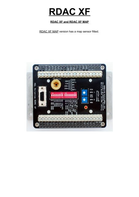
<strong>RDAC</strong> <strong>XF</strong><strong>RDAC</strong> <strong>XF</strong> and <strong>RDAC</strong> <strong>XF</strong> MAP<strong>RDAC</strong> <strong>XF</strong> MAP version has a map sensor fitted.
Input ConnectionsTC 1 to 12GNDOIL POIL TFUEL PCOOLCURRInputs for use with thermocouple temperature probes. Typcallyused for EGT probes (K-types) and CHT probes (K or J types).Can also be used for other types of temperature monitoringdepending on abilities of connected system.Grounding point. Connected to the engine block, also used asground for sensors not electrically connected to the engine itselfsuch as flow senders and current senders.Oil pressure senderOil temperature senderFuel pressure senderCoolant temperature senderElectrical current sender (Example: <strong>MGL</strong> magnetic currentsender)FL 1 Fuel level sender for tank 1FL 2 Fuel level sender for tank 2AUX 1 & AUX 2RPM 1 Engine RPM input 1RPM 25V OUTFF 1 Fuel flow sender 1FF 2MAP SensorAuxiliary inputs. Used for example for Rotax 912/914 NTC typeCHT probesEngine RPM input 2 (also used for Rotor RPM for some systems)5V DC supply output. Intended only for low current users (30mAmaximum). Typically used as supply point for <strong>MGL</strong> fuel flowsenders.Fuel flow sender 2 (also used for tank return flow sender in adifferential flow <strong>installation</strong>)This 1/8” NPT fitting connects to an internal MAP pressure sensor(Range: 0.2 – 2.5 Bar). Optional, fitted to <strong>RDAC</strong> <strong>XF</strong> MAP
DB9 Connectionspin 1 OPT- Used only with EFIS systems fitted with a three way <strong>RDAC</strong>connector.Connect to “- or Ground” of <strong>RDAC</strong> connector.pin 2 TX RS232 TX line. Used for OEM applications only.pin 3 RX RS232 RX line. Used for OEM Applications only.pin 4 OPT+ Used only with EFIS systems fitted with a three way <strong>RDAC</strong>connector.Connect to center connector (signal) of <strong>RDAC</strong> connector.pin 5 GND Ground. Connect this to engine block (and engine block to batterynegative). Do not connect directly to battery negative. This must berouted via the engine block.pin 6 CAN+ CANH signal line to EFISpin 7 CAN- CANL signal line to EFISpin 8 VIN +12V supply from battery via power switch / circuit breaker and fuseif required.pin 9 GND Ground. Connect this to engine block (and engine block to batterynegative). Do not connect directly to battery negative. This must berouted via the engine block.This terminal may be left unconnected if desired, it is connected topin 5 internally.DIP Switches<strong>RDAC</strong> SEL B & <strong>RDAC</strong> SEL AThese switches are used to assign each<strong>RDAC</strong> in the system with an ID number.up to four <strong>RDAC</strong>s can be connected at thesame time on the CAN interface.Note: set both switches to “off” for a single<strong>RDAC</strong> <strong>installation</strong>.AUX 1 PU used to pull the AUX 1 sensing line highAUX 2 PU used to pull the AUX 2 sensing line highOIPP PD used to pull the OILP line lowOIPP PU used to pull the OILP line highFuel P PU used to pull the Fuel Pressure sensing linehighCoolant PU used to pull the Coolant sensing line highFuel level 2 PUFuel level 1 PURPM 2 Filterused to pull the Fuel level 2 sensing linehighused to pull the Fuel level 1 sensing linehighAdds a high frequency filter to the signal
RPM 2 BallastRPM 2 High GainRPM 1 FilterRPM 1 BallastRPM 1 High GainPD = pull down resisterThis drawing illustrates the pull up resister circuitpathused when the RPM 2 signal line requires a220 ohm ballast resister to groundused when the RPM 2 signal needs a HighGain (increases signal sensitivityapproximately by a factor 10)Adds a high frequency filter to the signalpathused when the RPM 1 signal line requires a220 ohm ballast resister to groundused when the RPM 1 signal needs a HighGain (increases signal sensitivityapproximately by a factor 10)PU = pull up resisterThis drawing illustrates the pull up and pull down resistercircuit for the oil pressureThese circuits shows how the various PU switches feeds 5 volt onto the input(sense) line ifrequired. Please check the senders information for type and settings needed.The 2 nd circuit shows a pull down circuit that has a 100Ω load resister switched to GND.This intended for use with the Rotax 4-20 mA oil pressure sender. The white wire isconnected to the OILP input on the <strong>RDAC</strong> <strong>XF</strong>. The OILP PD switch must be in the ONposition and the OIL PU switch must be in the OFF position.Passive senders such as resistive temperature and pressure senders will require the pullupresistor to be “ON”. If you are using active senders (mostly used as electronic pressuresenders) please switch the pull-up resistor “OFF”.Default settings for most <strong>installation</strong>s (assuming the Rotax 4-20mA sender is not used):
Sensitivity gain adjustRPM 1 MIN MAXRPM 2 MIN MAXAdjusts sensitivity of the RPM1 inputAdjusts sensitivity of the RPM2 inputSensitivity to input signals on the RPM inputs can be adjusted over a wide range I twoswitchable ranges (via the DIPSwitch selection, high and low range).Highest sensitivity achievable is around 0.4V peak to peak in high gain and 4V peak topeak in low gain. From this level, the trimmers can be used to reduce the gain over a verywide range to around 50V peak to peak or higher depending on trimmer setting.IndicatorThe green LED flashes at about 1Hz during operation. If the LED is steady “ON” there is aserious fault with the <strong>RDAC</strong> and it cannot operate. If the LED is “OFF” the <strong>RDAC</strong> is notbeing supplied with power or there is a serious fault with the <strong>RDAC</strong>.INSTALLATIONPrecautionsNote that the unit is not waterproof, when installing the unit in a location where it will beexposed to fluids it is advisable to install it in an enclosure(box)This unit is intended for mounting on the aircraft's fire-wall,engine side.The unit is not designed for mounting directly to the engine!Excessive vibration , moisture and temperature extremes will damage the <strong>RDAC</strong> orshorten its life span.Advisory !Once <strong>installation</strong> is complete and all setups regarding <strong>RDAC</strong> <strong>XF</strong> are done, it is importantfor the dip switches and sensitivity gain adjustment to be covered (Suggestion: clear selfadhesive film)This is to prevent dust and moisture getting in to the switches, variable resisters and othercomponents.
<strong>RDAC</strong> <strong>XF</strong> DIMENSIONSWIRINGIt is important to connect the <strong>RDAC</strong> ground wire to the engine block. Failure to do so willresult in the readings from the engine sensors to be incorrect. Please note that thefollowing steps need to be done correctly otherwise unit may function incorrectly ordamage could result from bad <strong>installation</strong>. Take care to insulate all exposed connections.Plan your wire routings carefully to minimise chaffing of cables. The engine compartmentmay get hot so use suitable wire.Make neat connections with minimal exposed wire showing from connectors. If you are notsure, then ask for advise from an AMO.Connecting to EFIS / I-EFISConnecting the <strong>RDAC</strong> to an EFIS / IEFIS can be done in one of three ways.The ENIGMA, VOYAGER and ODYSSEY G1 EFIS units can only use the OPTconnection.OPT (optical) is the the connection that is used on the EFIS units and connects to the<strong>RDAC</strong>1 input on the back of the units.The ODYSSEY G2(pending relevant software updates) and the IEFIS systems use onlythe CAN interface.XTreme EFIS, XTreme EMS can use one <strong>RDAC</strong> <strong>XF</strong> connected via CAN interface.
Connection to an ENIGMA, VOYAGER or ODYSSEY G1 and G2The <strong>RDAC</strong> <strong>XF</strong> has a RS232 connection .This connection is only used for OEM and 3 rd partyapplications and is not used with any of <strong>MGL</strong> systems!Connections to an ODYSSEY G2 and I-EFIS unitsWhen using CAN interface, you can connect up to four <strong>RDAC</strong> <strong>XF</strong> s together.Observe the polarity of the two CAN wires. One of the lines is called “CAN-” or “CANL”, theother “CAN+' or “CANH” depending on equipment. It is recommended that a twisted pairwire is used for this connection using two wire colors for ease of identification. The CANbus must be terminated at each end with a 120 ohm resistor. Connections from equipmentinto the CAN bus (other than the ends) must only use short stubs into the bus (maximumlength of a stub should not exceed 20cm if possible).It is OK to use only a single resistor of value 60-120 ohms if the total length of the CANbus is not more than two meters (6 feet).You will need to set the <strong>RDAC</strong> SEL switches to the correct order so the ODYSSEY G2and IEFIS depending on the number of <strong>RDAC</strong> units you have on your bus. Normally, onlya single unit is used and thus the two SEL switches are set to “off”.Table for Rdac numberThe CAN bus will typically be shared with other equipment such as AHRS, compass,transponders etc. Please ensure that the CAN bus wiring is done to high standards and allconnections are secure as this is a critical link in your aircraft.
Thermocouple Probes Inputs (egt/cht)TC 1 to 12 provide up to 12 channels for thermocouple temperature sensors. You can use“K” TYPE thermocouple probes for EGT and “K or J” TYPE thermocouple probes as CHTsensors. Note that you need to setup the EFIS so it knows the probe types and whatchannels you are using..The TC setups on Enigma, Voyager, Odyssey G1 and G2 unitsare programmed to see the first TC inputs as EGTs thenfollowed immediately by CHTs. Example: 2 EGTs and 4 CHTsthen TC1=EGT1, TC2=EGT2, TC3=CHT1, TC4= CHT2,TC5=CHT3 and TC6=CHT4.On IEFIS systems you can assign TC channels as you prefer. It is however recommendedto follow the above guide by grouping your EGT probes starting at TC1, followed by agroup of CHT probes.Depending on how many probes used for the engine ,it is possible to use open TC inputswith probes for monitoring other components like bearings, pulleys or gearboxes ect. Notethat you need to use the screen design program to add these extra items into your desiredscreen pages on the IEFIS or EFIS systemsNote that thermocouple sensors can not be sheared across two <strong>RDAC</strong>s.These are some examples of “J” and “K” type thermocouple lead colour codesand corresponding polarity
Fuel Level InputsFL 1FL 2connects to fuel level sender output/signal from tank1connects to fuel level sender output/signal from tank 2 ( if installed)Safety Hazard ! Please read this:Be careful when installing fuel level senders into fuel tanks. Ensure that thefuel tank is completely empty when you proceed with the <strong>installation</strong>. Ensurethat the fuel tank is well ventilated and does not contain any fuel vapors –these are highly explosive when mixed with air.Ensure that at all times the ground connection (the connection of the fuel levelsender mounting flange) is securely connected to the aircraft frame (in case ofa metal frame) and to the negative terminal of the battery. In addition thenegative terminal of the battery must at all times be connected to the Supplyground terminal of the <strong>RDAC</strong> X EMS.Please note – this wiring is critical and must never break in flight. It would bepossible to create electrical sparks in the fuel tank if your wiring is faulty orincorrect. The consequences of this can be imagined. This has nothing to dowith the <strong>RDAC</strong> EMS itself but is a general hazard for any automotive fuel levelsender <strong>installation</strong>.If you have no experience with electrical wiring, PLEASE delegate the task toa qualified automobile electrician or electronics technician.If you need to remove the <strong>RDAC</strong> X EMS, please first disconnect and securethe fuel level sender wire before disconnecting anything else.
Aux InputsAUX 1AUX 2is an axillary input for extra temperature sensors( cht1,coolant)is an axillary input for extra temperature sensors (cht2)The AUX inputs can be used to measuretemperature or pressure with the use of a variable resistanceNTC type probes.Electronic sensors such as the popular type LM335 canalso be used.This is a typical Rotax 912/914 CHTsensor connection. With this setup theAUX 1 PU and AUX 2 PU switcheswill be in the ON position.
Rpm InputsRPM 1unitsRPM 2This input connects to one of your magneto, ignition, ecu or pick-upThis input can be used to see your second mag rpm( dual magneto, ecu or ignition units)This input is also setup for EXTREME units to get a rotor rpm feed.( auto gyro or helicopters) This setup is only for the Xtreme EFIS!On the EFIS AND IEFIS units the RPM generally works by taking the highest RPM readingfor display on the standard screens.This drawing of a system that uses a pick-up sensor (Hall Effect Sensor) sometimes seenon Rotax enginesEach RPM input has the following options:Noise filter: This can be switched into the signal path to help in removing high frequencynoise artefacts from the signal that can result in unstable readings. Use this switch only ifyou rely on a “dirty” signal. An example of such a signal is a direct coupling to a magnetodevice.Ballast resistor: This switches a 220 ohm ballast resistor to ground. This can be used toreduce noise or secondary pulses on the RPM line. Often used with Rotax engines. Note:For direct magneto pickups this switch must be “OFF” as otherwise the magneto pulsemay have low energy in particular at idle.Gain setting: Switch “on” selects a high gain. In this case the input is about 10 times moresensitive than normal. Used only for low level signals such as inductive pickup coils.
Typical sensitivity settings and resultant minimum signal levels:RPM 1 shows ¼ turn RPM 1 shows mid position RPM 1 shows max positionRPM 1 High Gain on 3.5 volt (peak to peak) 0.8 volt (peak to peak) RPM 1 High Gain on RPM 1 High Gain ON 0.4 volt (peak to peak)RPM High Gain OFF 35 volt (peak to peak) RPM High Gain OFF 8 volt (peak to peak) RPM High Gain OFF 4 volt (peak to peak)RPM 1 High Gainturned ONRPM 1 High Gainturned OFFECU units may have a digitalRPM output you may be ableto useThis a drawing of a magneto system. In this casethe RPM feeds are taken from the “P” connectionterminal.Note that the two magnetos are connected tothe appropriate RPM inputs with arecommended 10KΩ (10.000 ohms)resister in line. In this case you wouldhave the RPM 1&2 BALLAST switches inthe OFF position.
Fuel Flow InputsThis example is based on typical <strong>MGL</strong> flow senders:FF1 & FF2 Connection of fuel flow sender ( Braid to GND, Red to +5 volts, Blue to FF1)If a second fuel flow sensor is used then the braid and red wires of the secondflow sender connect as the first sender but the blue wire (signal) connects toFF2.Using the Fuel Flow SenderNote the setup for Fuel flow senderon EFIS unit ”Fuel related setup;Fuel flow setup menu”“Flow sender type Rdac one: TurbineIt is important to install thefuel flow sender at an angle so thatwill no bubbles can get trapped in theimpeller section. This will causeincorrect or erratic readings.It is also important to work out what fuel flowto expect (generally manufacturers specify fuel usage per hour)in order to select the right jet for the fuel flow sender unit.Please note that the <strong>installation</strong> of the Fuel Flow sender should be done insuch a fashion that dirt or debris from the fuel tank cannot lodge inside theflow sender. These will not block your fuel flow but may lead to the impellerinside the sender jamming. It is usually sufficient to mount the Flow senderAFTER the fuel filter but before the fuel pump. It is a good idea to provide asmall reservoir such as a primer bulb between the flow sender and the fuelpump.Using InjectorsIn this injector system is the injectorhas a +12volts connection but thenegative (low) side of the injector isswitched/fired by the electronicinjector control system.For this reason in ”Fuel relatedsetup;Fuel flow setup menu” the selectionshould show as “Flow sender typeRdac one: InjectorL”Most systems used are lowtriggering/firing systemsIf a positive(high) switching/ firinginjector system is used then theselection will show“Flow sender type Rdac one: InjectorH”
Manifold Air Pressure InputPlease note that the MAP Sensor is only available on th <strong>RDAC</strong> <strong>XF</strong> MAPThe MAP Sensor is connected to the manifold.This sensor measures the air pressure or vacuum in the manifold.In the case of the 912 and 914 Rotax engines there is a pipe connectingthe two manifolds where this connection can be made.On the <strong>RDAC</strong> there is a standard 1/8 th NPT female threaded fitting.
Temperature monitoring connection for Rotax 582A typical sensor connection layout
Technical dataWeight <strong>RDAC</strong> <strong>XF</strong>Weight <strong>RDAC</strong> <strong>XF</strong> MAPPower supply:CAN bus:RS232:OPT:Temperature range:340 grams370 grams9-18V DC. DO-160 compliant to 120V/10mS pulse250kBaud, 11bit identifiers, <strong>MGL</strong> CAN bus protocol38400 Baud1250 Baud-30 degrees C to +70 degrees C ambient (operation)Thermocouple common mode range: -2V to +3V with respect to GND terminalsThermocouple temperature range: up to 1200 degrees C (K-type probes)Analog input pull up resistors to +5V:AUX1, AUX2, OILT, COOL: 1500 ohmsOILP: 1000 ohmsFL1, FL2: 220 ohmsRPM inputs:Input impedance (A/C coupled):High gain: 15.000 ohmsLow gain: 110.000 ohmsBallast resistor (switchable): 220ohms, 5W to GND, DC coupled