Deterministic protocols for real-time communication in multiple ...
Deterministic protocols for real-time communication in multiple ...
Deterministic protocols for real-time communication in multiple ...

You also want an ePaper? Increase the reach of your titles
YUMPU automatically turns print PDFs into web optimized ePapers that Google loves.
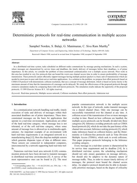
S. Norden et al. / Computer Communications 22 (1999) 128–136 131Table 1Node and channel status table (MDCR)Time N 1 N 2 N 3 N 40 (5, 17) (2, 6) (2, 9) (2, 12)1 C C C C2 N (5, 17)3 X (5, 17)4 X (5, 17) D (2, 6)5 X (5, 17)7 X (5, 17) D (2, 9)8 I I9 N (2, 12)10 X (2, 12)11respect to its predecessor, and modify<strong>in</strong>g the laxity of itssuccessor. Messages with negative laxity are removed fromthe queue.The LDCR protocol consists of three phases, namely,contention mode, collision resolution (CR) mode, andleast laxity first (LLF) mode, which are described below.This comb<strong>in</strong>ation of CR mode and LLF mode def<strong>in</strong>es anepoch <strong>in</strong> the LDCR protocol as contrasted to the DCR preorder and MDCR <strong>protocols</strong> where<strong>in</strong> an epoch is the CRmode alone.1. Contention mode (when channel is idle)(a) Each node exam<strong>in</strong>es the message at the head of itsqueue. If the laxity of the message is negative, themessage is dropped.(b) Otherwise, it attempts to transmit notifier <strong>for</strong> themessage.(c) If the notifier transmission is successful, themessage is transmitted.(d) If a collision occur dur<strong>in</strong>g notifier transmission, allnodes enter <strong>in</strong>to CR mode by travers<strong>in</strong>g the CR tree <strong>in</strong>pre order.Table 2Node and channel status table (LDCR). C: Collision; N: Notifier; X: Transmit;D: Drop; L: Laxity; I: IdleTime N 1 N 2 N 3 N 40 (5, 17) (2, 6) (2, 9) (2, 12)1 C C C C2 N (5, 17)3 Defer (L 1 ˆ 9) C C4 (L 1 ˆ 8) N (2, 6)5 (L 1 ˆ 7) X (2, 6)7 (L 1 ˆ 5) N (2, 9)8 X (2, 9)10 (L 1 ˆ 2) N (2, 12)11 X (2, 12)12 LLF mode – (L 1 ˆ 0): X (5, 17)172. Collision resolution mode(a) When a node n i gets its turn <strong>in</strong> the CR mode, ittransmits its notifier. Thus every other node is <strong>in</strong><strong>for</strong>medof the message requirements of node n i(b) If the laxity of a message (first message at queue ofn i ) is less than a threshold (but non-negative), then themessage is transmitted, else the message is deferred andper order traversal cont<strong>in</strong>ues. It two or more messageshave the laxity less than or equal to the threshold value,the preference is given to message with shorter service<strong>time</strong>. This m<strong>in</strong>imizes the <strong>time</strong> that the channel isblocked, thereby improv<strong>in</strong>g the chances of successfultransmission <strong>for</strong> subsequent messages.(c) Even after the CR tree is completely traversed, ifsome deferred messages are still to be transmitted, theprotocol enters <strong>in</strong>to the LLF mode.3. LLF mode(a) In the LLF mode, all the deferred messages aretransmitted, based on the least laxity order of messagesamong nodes. This phase is required to enable thosemessages, that arrived <strong>in</strong> the current epoch, to be transmittedbe<strong>for</strong>e the next epoch. By do<strong>in</strong>g this, the overhead<strong>in</strong>curred as result of collision between messages oftwo different epochs is elim<strong>in</strong>ated.(b) If all the messages are either transmitted or dropped,the next epoch beg<strong>in</strong>s.Note that the threshold value mentioned <strong>in</strong> Step 2(b) isfixed, <strong>in</strong> our protocol, to be one. The importance of thisvalue, is brought out <strong>in</strong> a subsequent section, when compar<strong>in</strong>gthis protocol with another representative protocol.3.4.2. Illustrative examplesIn this section, we demonstrate the effectiveness of theLDCR over MDCR with an illustrative example. The exampleconsiders a LAN with 4 nodes. Tables 1 and 2 depict thework<strong>in</strong>g of MDCR and LDCR, respectively. The first entry(at <strong>time</strong> 0) <strong>in</strong> these tables is the <strong>in</strong>itial status of the queue ateach node (each node has a s<strong>in</strong>gle message to transmit). Forexample, node N 1 has a message hav<strong>in</strong>g deadl<strong>in</strong>e of 17 andrequir<strong>in</strong>g 5 slots <strong>for</strong> transmission. In this example, the preorder traversal of CR tree (b<strong>in</strong>ary tree), as shown <strong>in</strong> Fig. 1, is<strong>in</strong> the order of N 1 ,N 2, N 3, and N 4.Let us trace a few steps <strong>in</strong> the MDCR protocol shown <strong>in</strong>Table 1. At <strong>time</strong> 1, all nodes attempt to transmit their notifierwhich results <strong>in</strong> collision, thus all nodes enter the CRmode. At <strong>time</strong> 2, N 1 (root of the CR tree) transmits itsnotifier, and proceeds to transmit its message from <strong>time</strong>slot 3 onwards, <strong>for</strong> 5 <strong>time</strong> slots. Thus all nodes back off<strong>for</strong> a period of 5 slots. Even though the laxity of thismessage is very large (10), compared to the laxity of othermessages, it is still transmitted. As result, the other nodes allend up hav<strong>in</strong>g negative laxity, when they get their turn. By<strong>time</strong> 8, two nodes <strong>in</strong> the left subtree (N 2 and N 3 ) would droptheir messages, as their laxities become negative at the end
132S. Norden et al. / Computer Communications 22 (1999) 128–136Fig. 1. Mapp<strong>in</strong>g of nodes <strong>in</strong>to vertices of CR tree.of slot 4 and 7, respectively. At <strong>time</strong> 9, the node <strong>in</strong> the rightsubtree (N 4 ) will transmit its notifier successfully, and transmitsits message successfully be<strong>for</strong>e the deadl<strong>in</strong>e.For the LDCR protocol, the threshold used <strong>for</strong> defermentis taken to be 1. The behaviour of LDCR protocol is similarto MDCR up to <strong>time</strong> 2, i.e., after transmission of the notifierof message at N 1 . After transmission of the notifier, theLDCR computes the laxity <strong>for</strong> this message and f<strong>in</strong>ds thatthe laxity is greater than threshold, hence defers themessage. At <strong>time</strong> slot 4, N 2 transmits its notifier, and f<strong>in</strong>dsthat the laxity of the message is zero, hence the message istransmitted immediately. The protocol proceeds <strong>in</strong> thismanner.From the above example, it can be noted that the LDCRprotocol transmits all the messages successfully, while theMDCR protocol can transmit only 50% of the messages.The key aspect that contributes to the improved per<strong>for</strong>mance<strong>in</strong> LDCR is the deferment of the message at N 1 ,which has a large laxity. This allows more critical messagesat N 2 , N 3 , etc., to be transmitted be<strong>for</strong>e their deadl<strong>in</strong>es.4. Simulation studiesTo study the effectiveness of the proposed <strong>protocols</strong>, wehave conducted extensive simulation studies. For eachsimulation run, 10000 messages were generated <strong>for</strong> theentire system. For the per<strong>for</strong>mance results, 95% confidence<strong>in</strong>tervals were obta<strong>in</strong>ed. The per<strong>for</strong>mance metrics used, andthe simulation model are def<strong>in</strong>ed below:4.1. Simulation model and parameters• N: Number of nodes on the network.Table 3Simulation parametersParameter Explanation Value when varied (fixed)N Number of nodes 5…30 (10)M Average message length 7…20 (20) slotsa Laxity parameter 2…25 (10)Load l M N 0.1…1 (0.6)P/Nt Packet to Notifier ratio 2…10 (10)• M: Average message length (or service <strong>time</strong>).• a: Laxity parameter which decides the deadl<strong>in</strong>e ofmessages, directly proportional to deadl<strong>in</strong>e. The deadl<strong>in</strong>eis uni<strong>for</strong>mly chosen <strong>in</strong> the <strong>in</strong>terval [C i ,a*C i ].• l: Mean message arrival rate at a node. Message arrivalat each node follows Poisson distribution with mean arrivalrate l.• L: Load on the network is def<strong>in</strong>ed as the product ofnumber of nodes (N), mean message length (M), andthe arrival rate, i.e., L ˆ (l * M * N).• (P/Nt): Packet to notifier ratio. As mentioned earlier, slotis a basic unit of transmission <strong>in</strong> which one packet can betransmitted. We fix a normalized value of packet slot tobe 10 <strong>time</strong> slots, and from this ratio, we can determ<strong>in</strong>ethe number of slots used by transmission of a notifier,relative to this normalized value of a packet slot.The simulation parameters and their ranges are given <strong>in</strong>Table 3.4.2. Per<strong>for</strong>mance metrics• Success Ratio (SR): This is def<strong>in</strong>ed as the ratio of thetotal number of messages transmitted successfully to thetotal number of messages that arrived <strong>in</strong> the system. TheSR is an important metric which reflects the throughputof the network.• Effective Channel Utilization (ECU): This is the ratio ofthe <strong>time</strong> slots used <strong>for</strong> successful transmission to thenumber of <strong>time</strong> slots that elapsed until all messageswere transmitted or dropped. A higher value of ECUwould imply that the channel utilization, as result ofsuccessful message transmission, is large compared tothe net overhead as result of collision and notifier transmission.• Normalized Transmission Length (NTL): This is theratio of the mean length of the transmitted messages tothe mean length of the generated messages. The closer itsvalue to one, the less bias towards longer or shortermessages. In other words, when the NTL offered by aprotocol is one, the protocol behaves <strong>in</strong>dependent ofmessage service <strong>time</strong>.4.3. Results and discussionIn this section, we compare the per<strong>for</strong>mance of theproposed <strong>protocols</strong> (MDCR and LDCR) with a recentlyproposed protocol called PBCSMA. The PBCSMA protocolis chosen <strong>for</strong> comparison because it can support multipacketmessages, and has been reported to per<strong>for</strong>m better than theVTCSMA and CSMA based <strong>protocols</strong> [15]. It is a modifiedversion of p-persistent CSMA with support <strong>for</strong> differentpriority levels of traffic. Note that the MDCR, LDCR, andPBCSMA are best ef<strong>for</strong>t <strong>protocols</strong>, which means that theyadmit all the messages arriv<strong>in</strong>g <strong>in</strong> the system, withoutguarantee<strong>in</strong>g that these messages will be transmitted
S. Norden et al. / Computer Communications 22 (1999) 128–136 133Fig. 2. Effect of load on (a) SR,(b) ECU,(c) NTL.successfully. In the simulation plots, these <strong>protocols</strong> arelabelled as with an extension BE to <strong>in</strong>dicate ‘‘Best Ef<strong>for</strong>t’’.For the sake of completeness, we describe the PBCSMAprotocol as given below:The PBCSMA protocol• A message is characterized as critical, if its laxity is lessthan a predef<strong>in</strong>ed threshold, otherwise it is classified asnon-critical.• Transmission of a critical message beg<strong>in</strong>s with the broadcastof a notifier, similar to our protocol.• When a new message arrives and is classified as eithercritical or non-critical, and the channel is idle, themessage is sent. Otherwise (i.e., the channel is busy),if the message currently be<strong>in</strong>g transmitted is not critical,it is preempted to allow a critical message to besent.• Transmission of a non-critical message from a node isnot possible as long as the channel is busy. Also, themessage is not sent right after the channel becomesidle. The node waits <strong>for</strong> one slot, and if the channelrema<strong>in</strong>s idle, the message is sent.• Follow<strong>in</strong>g a collision, a non-critical message issuspended <strong>for</strong> the duration of a slot, and if that slot isnot occupied by a critical message, the non-criticalmessage is retransmitted with probability P i .• If a critical message collides, it is retransmitted immediatelywith probability P i .From the Figs. 2(a)–5(a), it can be observed that the SRoffered by LDCR is better than the other two <strong>protocols</strong> ofwhich the MDCR is better than PBCSMA. From Figs. 3(b)–5(b), the ECU obta<strong>in</strong>ed us<strong>in</strong>g LDCR is higher (better) thanthe other two because of its SR. Similarly, the NTL offeredby LDCR is closer to one as compared to the other <strong>protocols</strong>.The reasons <strong>for</strong> these observations are discussedbelow:• LDCR is better than PBCSMA: The reasons, why LDCRis an improvement over PBCSMA, are as follows. In thecase of the notifier of a critical message collid<strong>in</strong>g with thenotifier transmission of another critical message,PBCSMA will retransmit the <strong>in</strong>terrupted message withcerta<strong>in</strong> probability. When the threshold is large, onecould have several critical messages which require tobe transmitted. Repeated attempts at retransmission withoutproper arbitration <strong>in</strong> the CSMA fashion will lead toseveral collisions utiliz<strong>in</strong>g several slots which <strong>in</strong> turnleads to miss<strong>in</strong>g of message deadl<strong>in</strong>es. Whereas <strong>in</strong>LDCR-BE, by <strong>for</strong>c<strong>in</strong>g the threshold <strong>for</strong> critical messagesto be one, the protocol restricts the number of criticalmessages; <strong>in</strong> the event of collision, the arbitration isdone as per the pre order traversal of the CR treeFig. 3. Effect of a on (a) SR, (b) ECU, (c) NTL.
134S. Norden et al. / Computer Communications 22 (1999) 128–136Fig. 4. Effect of N on (a) SR,(b) ECU,(c) NTL.allow<strong>in</strong>g one of the nodes to transmit <strong>in</strong> subsequent slotswithout wast<strong>in</strong>g the bandwidth. Further, <strong>in</strong> LDCR, whentwo critical messages have laxities less than the thresholdvalue, the smaller message is transmitted whichimproves the chances of subsequent messages. AsPBCSMA is a preemption based protocol, if a non-criticalmessage is preempted as result of the presence ofseveral critical messages, the assumption made <strong>in</strong> [15]is that the non-critical message will have a large enoughdeadl<strong>in</strong>e so as to still be transmitted after all the criticalmessages. This will not hold especially when the thresholdis large and there are a large number of criticalmessages wait<strong>in</strong>g <strong>for</strong> channel access. The subsequentdelay <strong>in</strong>curred by the non-critical message may make itcritical, lead<strong>in</strong>g to degradation <strong>in</strong> the protocol as thenumber of critical messages steadily <strong>in</strong>creases. Another<strong>in</strong>terest<strong>in</strong>g observation about PBCSMA that re<strong>in</strong><strong>for</strong>cesthe above po<strong>in</strong>t, also made by the author <strong>in</strong> [15], is thatthe SR will degrade when the threshold is <strong>in</strong>creasedbeyond a certa<strong>in</strong> value, as the number of criticalmessages (with vary<strong>in</strong>g degree of criticality) <strong>in</strong>creases.This results <strong>in</strong> <strong>in</strong>creased number of collisions betweenthese messages, thereby reduc<strong>in</strong>g the SR. The <strong>in</strong>creasednumber of collisions will also result <strong>in</strong> a lower ECUvalue. In addition, it may also result <strong>in</strong> priority <strong>in</strong>version,as high laxity (non-critical) messages would contend <strong>for</strong>the channel along with low laxity (critical) messages.The <strong>in</strong>creased number of collisions will also result<strong>in</strong> a lower ECU value. This situation will not arise<strong>in</strong> LDCR, as it defers the non-critical messages to aseparate mode (LLF), thus avoid<strong>in</strong>g collisions betweenmessages with high and low laxities. This will reducethe number of overall collisions. These deferredmessages are transmitted <strong>in</strong> the LLF mode, us<strong>in</strong>glaxity based order<strong>in</strong>g. This systematic way of collisionresolution and message deferment results <strong>in</strong> improvedSR and ECU. The superiority of the LDCR protocolover PBCSMA, can be clearly seen, from all the simulationgraphs.• LDCR is better than MDCR: The relatively poor per<strong>for</strong>manceof MDCR is ow<strong>in</strong>g to its bl<strong>in</strong>d transmission ofmessages as per the static position of nodes <strong>in</strong> the CR treewithout tak<strong>in</strong>g <strong>in</strong>to account the laxity of messages amongthe nodes. Thus higher priority (lower laxity) messageswill be treated <strong>in</strong> the same way as lower priority (largelaxity) messages. This will lead to miss<strong>in</strong>g of messagedeadl<strong>in</strong>es. Further, a large number of messages with tighterlaxity, hav<strong>in</strong>g small service <strong>time</strong>s, could be dropped ifa message with larger laxity, and hav<strong>in</strong>g larger service<strong>time</strong>, is transmitted. This scenario is brought out by thehigh NTL values, shown by the MDCR protocol, <strong>in</strong> Figs.2(c)–5(c). From the Figs. 2(a)–5(a), which study theFig. 5. Effect of P/Nt ratio on (a) SR,(b) ECU,(c) NTL.
S. Norden et al. / Computer Communications 22 (1999) 128–136 135effect of the different <strong>in</strong>put parameters, on SR, we canconclude the follow<strong>in</strong>g:• SR vs Load: In Fig. 2(a), as load <strong>in</strong>creases, there is apredictable fall <strong>in</strong> SR values <strong>for</strong> all the three <strong>protocols</strong>as more number of messages are generated and morenumber of collisions, thus reduc<strong>in</strong>g SR.• SR vs a: In Fig. 3(a), as the laxity factor <strong>in</strong>creases, thedeadl<strong>in</strong>e associated with every message <strong>in</strong>creases,result<strong>in</strong>g <strong>in</strong> an <strong>in</strong>crease <strong>in</strong> the number of messagesthat are transmitted successfully, hence <strong>in</strong>creas<strong>in</strong>g SR.• SR vs N: In Fig. 4(a), as the number of nodes<strong>in</strong>creases, the SR falls. This is the result of an <strong>in</strong>crease<strong>in</strong> the number of messages, as well as a larger epoch<strong>time</strong>, which leads to more messages miss<strong>in</strong>g theirdeadl<strong>in</strong>es.• SR vs P/Nt: In Fig. 5(a), as P/Nt is decreased, theper<strong>for</strong>mance will fall expectedly, as a smaller ratioimplies a larger overhead as result of notifier transmission,compared to actual packet transmission.An <strong>in</strong>terest<strong>in</strong>g observation from the graphs is that theECU is not always <strong>in</strong>fluenced by the SR. Normally, onewould expect that as SR decreases, the ECU will alsodecrease s<strong>in</strong>ce less number of slots are used <strong>for</strong> successfultransmission. Some<strong>time</strong>s, this relation may not hold wheneven if less number of messages are transmitted, thecomb<strong>in</strong>ed service <strong>time</strong>s may exceed those of the droppedmessages, which will still <strong>in</strong>crease the ECU (see Fig. 2(a)and (b)). This explanation is supported by the <strong>in</strong>creas<strong>in</strong>gNTL values (<strong>in</strong> Fig. 2(c)) with <strong>in</strong>creas<strong>in</strong>g load, <strong>for</strong> all the<strong>protocols</strong>, imply<strong>in</strong>g that messages with larger service <strong>time</strong>sare transmitted.5. ConclusionsIn this article, we have identified the need <strong>for</strong> <strong>real</strong>-<strong>time</strong><strong>protocols</strong> to support multipacket <strong>real</strong>-<strong>time</strong> message transmissionwhich is the <strong>for</strong>m of <strong>communication</strong> <strong>in</strong> a typical<strong>real</strong>-<strong>time</strong> system. We have highlighted the <strong>in</strong>adequacy ofthe exist<strong>in</strong>g <strong>protocols</strong> to support this requirement. As a solutionto the problem, we have proposed <strong>protocols</strong> with bestef<strong>for</strong>t service <strong>for</strong> <strong>multiple</strong>-access networks, namely, theLDCR and MDCR <strong>protocols</strong>. The MDCR is an extensionof DCR protocol while the LDCR protocol is based on theconcept of message deferment.We have demonstrated the effectiveness of our best ef<strong>for</strong>t<strong>protocols</strong> through simulation, <strong>for</strong> a wide range of parameters<strong>for</strong> <strong>multiple</strong> per<strong>for</strong>mance metrics, by compar<strong>in</strong>gthem with a protocol (PBCSMA) recently proposed <strong>for</strong>the same problem. Our simulation results reveal that theLDCR protocol per<strong>for</strong>ms better than the PBCSMA andMDCR <strong>for</strong> all the three per<strong>for</strong>mance metrics – successratio, effective channel utilization, and normalized transmissionlength. We are currently study<strong>in</strong>g the effect of dynamicallyassign<strong>in</strong>g more than one vertex <strong>in</strong> the CR tree to anode, allow<strong>in</strong>g additional messages to be sent <strong>in</strong> the sameepoch.References[1] K. Arv<strong>in</strong>d, K. Ramamritham, J.A. Stankovic, W<strong>in</strong>dow MAC <strong>protocols</strong><strong>for</strong> <strong>real</strong>-<strong>time</strong> <strong>communication</strong> services, Technical Report, Universityof Massachusetts, USA, 1992.[2] J.I. Capetanakis, Tree algorithm <strong>for</strong> packet broadcast channels, IEEETrans. on Communications 27 (10) (1979) 1476–1484.[3] D.E. Comer, D.L. Stevens, Internet work<strong>in</strong>g with TCP/IP-Volume 2,Prentice-Hall International Inc, Englewood Cliffs, NJ, USA, 1994.[4] Intel Corp., CSMA/DCR determ<strong>in</strong>istic access LANs, PresentationViewgraphs, Folsom Microcomputer Group, Feb. 1988.[5] K.H. Kim, C. Serro, Robustness of <strong>real</strong>-<strong>time</strong> local area network <strong>protocols</strong>,Computer Communications 20 (1997) 169–176.[6] L. Kle<strong>in</strong>rock, Packet switch<strong>in</strong>g <strong>in</strong> radio channels: Part 1 – Carriersense <strong>multiple</strong> access modes and their throughput-delay characteristics,IEEE Trans. on Communications 23 (12) (1975) 1400–1416.[7] J.F. Kurose, M. Schwartz, Y. Yem<strong>in</strong>i, Multiple-access <strong>protocols</strong> and<strong>time</strong>-constra<strong>in</strong>ed <strong>communication</strong>, ACM Comput<strong>in</strong>g Surveys 16 (1)(1984) 43–70.[8] G. Le Lann, N. Rivierre, Real-<strong>time</strong> <strong>communication</strong>s over broadcastnetworks: The CSMA-DCR and the DOD-CSMA-CD <strong>protocols</strong>,Technical Report, Institute National De Recherche En In<strong>for</strong>matiqueEt En Automatique, France, Mar. 1993.[9] N. Malcolm, W. Zhao, Hard <strong>real</strong>-<strong>time</strong> <strong>communication</strong> <strong>in</strong> <strong>multiple</strong>accessnetworks, Real-<strong>time</strong> Systems 8 (1995) 35–77.[10] N. Malcolm, W. Zhao, The <strong>time</strong>d-token protocol <strong>for</strong> <strong>real</strong>-<strong>time</strong><strong>communication</strong>s, IEEE Computer 27 (1) (1994) 35–41.[11] S.K. Oh, G.J. Macewen, Task behaviour monitor<strong>in</strong>g <strong>for</strong> adaptive <strong>real</strong><strong>time</strong><strong>communication</strong>, Real-<strong>time</strong> Systems 11 (1996) 173–195.[12] R. Yavatkar, P. Pai, R. F<strong>in</strong>kel, A Reservation-based CSMA protocol<strong>for</strong> <strong>in</strong>tegrated manufactur<strong>in</strong>g networks, IEEE Trans. on Systems, Manand Cybernetics 24 (8) (1994) 1247–1257.[13] K. Ramamritham, Channel characteristics <strong>in</strong> local-area hard <strong>real</strong>-<strong>time</strong>systems, Computer Networks and ISDN Systems 13 (1987) 3–13.[14] J.A. Stankovic, K. Ramamritham, Hard <strong>real</strong>-<strong>time</strong> systems, ComputerSociety Press of IEEE, 1730, Massachussets Avenue, Wash<strong>in</strong>gton,DC, 1993.[15] O. Ulusoy, Network access protocol <strong>for</strong> hard <strong>real</strong>-<strong>time</strong> <strong>communication</strong>systems, Computer Communications 18 (12) (1995) 943–948.[16] V. Upadhya, Design and Analysis of Real-<strong>time</strong> LAN <strong>protocols</strong>, M.S.Thesis, Department of Computer Science and Eng<strong>in</strong>eer<strong>in</strong>g, IndianInstitute of Technology, Madras, Jan. 1996.[17] W. Zhao, K. Ramamritham, Virtual <strong>time</strong> CSMA <strong>protocols</strong> <strong>for</strong> hard<strong>real</strong>-<strong>time</strong> <strong>communication</strong>, IEEE Trans. on Software Eng<strong>in</strong>eer<strong>in</strong>g 13(8) (1987) 938–952.Samphel Norden obta<strong>in</strong>ed his B.Tech degree <strong>in</strong> Computer Science andEng<strong>in</strong>eer<strong>in</strong>g from the Indian Institute of Technology, Madras, <strong>in</strong> 1998.Currently, he is a research student at the Computer Science Department,University of Wash<strong>in</strong>gton at St. Louis, USA. His research areas of<strong>in</strong>terests are <strong>real</strong>-<strong>time</strong> networks and active networks.S. Balaji obta<strong>in</strong>ed his B.Tech degree <strong>in</strong> Computer Science and Eng<strong>in</strong>eer<strong>in</strong>gfrom the Indian Institute of Technology, Madras, <strong>in</strong> 1998.Currently, he is a research student at the Computer Science Department,University of Ill<strong>in</strong>ois at Urbana Champaign, USA. His researchareas of <strong>in</strong>terest are parallel and distributed comput<strong>in</strong>g and computernetworks.
136S. Norden et al. / Computer Communications 22 (1999) 128–136G. Manimaran obta<strong>in</strong>ed his B.E. degree <strong>in</strong> Computer Science andEng<strong>in</strong>eer<strong>in</strong>g from Bharathidasan University, Thiruchirappalli, <strong>in</strong>1989, his M.Tech. <strong>in</strong> Computer Technology from the Indian Instituteof Technology, Delhi, <strong>in</strong> 1993 and his Ph.D. <strong>in</strong> Computer Science andEng<strong>in</strong>eer<strong>in</strong>g from the Indian Institute of Technology, Madras, <strong>in</strong> 1998.His research <strong>in</strong>terests are resource management <strong>in</strong> parallel and distributed<strong>real</strong>-<strong>time</strong> systems, <strong>real</strong>-<strong>time</strong> networks and fault-tolerantcomput<strong>in</strong>g.C. Siva Ram Murthy obta<strong>in</strong>ed his B.Tech. degree <strong>in</strong> Electronics andCommunications Eng<strong>in</strong>eer<strong>in</strong>g from the Regional Eng<strong>in</strong>eer<strong>in</strong>g College,Warangal, <strong>in</strong> 1982, his M.Tech. <strong>in</strong> Computer Eng<strong>in</strong>eer<strong>in</strong>g from theIndian Institute of Technology (IIT), Kharagpur, <strong>in</strong> 1984 and hisPh.D. <strong>in</strong> Computer Science from the Indian Institute of Science(IISc), Bangalore, <strong>in</strong> 1988. From March to September, 1988, he workedas a Scientific Officer <strong>in</strong> the Supercomputer Education and ResearchCentre at IISc. He subsequently jo<strong>in</strong>ed IIT, Madras, as a Lecturer ofComputer Science and Eng<strong>in</strong>eer<strong>in</strong>g. He became an Assistant Professor<strong>in</strong> August 1989, and is currently an Associate Professor at the sameplace. He has held visit<strong>in</strong>g positions at the German National ResearchCentre <strong>for</strong> In<strong>for</strong>mation Technology (GMD), Sankt August<strong>in</strong>, Germany,the University of Wash<strong>in</strong>gton, Seattle, USA, and the University of Stuttgart,Germany. He is a recipient of the Seshagiri Kaik<strong>in</strong>i Medal <strong>for</strong> thebest Ph.D. thesis and also of the Indian National Science AcademyMedal <strong>for</strong> Young Scientists.