Quidway AR 28 Series Routers Installation Manual.pdf - Index of
Quidway AR 28 Series Routers Installation Manual.pdf - Index of
Quidway AR 28 Series Routers Installation Manual.pdf - Index of
- No tags were found...

You also want an ePaper? Increase the reach of your titles
YUMPU automatically turns print PDFs into web optimized ePapers that Google loves.
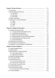
<strong>Installation</strong> <strong>Manual</strong><strong>Quidway</strong> <strong>AR</strong> <strong>28</strong> <strong>Series</strong> <strong>Routers</strong>Chapter 4 <strong>Installation</strong> <strong>of</strong> the RouterII. Recommended power outletThe user is recommended to use a single-phase 3-core outlet with a neutral point or amulti-functional computer power socket. The neutral point <strong>of</strong> the outlet should begrounded reliably. Normally, the neutral point <strong>of</strong> the power supply system in a building isburied in the ground during the construction and cabling. The user must make sure thatthe power supply for the building is grounded before connecting the AC power cord.III. Connection <strong>of</strong> AC power cordStep 1: Confirm that the PGND wire is correctly connected.Step 2: Make sure that the power switch for the router is placed in the OFF position.Then, connect one end <strong>of</strong> the power cord, which came with the device, to the powersocket on the rear panel <strong>of</strong> the router chassis, and the other end to the AC power outlet.Step 3: Press the power switch <strong>of</strong> the router to the ON position.Step 4: Check that the POWER LED on the front panel is on, which indicates that theconnection <strong>of</strong> power cord is correct.4.4.2 Connecting DC Power CordI. DC power supplyDC power supply input is in the range -48V to -60V DC.Rated voltage range: -48- -60V d.c.The following figure illustrates the partial external appearance <strong>of</strong> the power socket for aDC-powered router:-48 -60VBGND -48VPGNDPower switchDC inputFigure 4-7 Partial external appearance <strong>of</strong> the power socket for the DC-powered router4-7