Selection Guide - Tate Access Floors
Selection Guide - Tate Access Floors
Selection Guide - Tate Access Floors

Create successful ePaper yourself
Turn your PDF publications into a flip-book with our unique Google optimized e-Paper software.
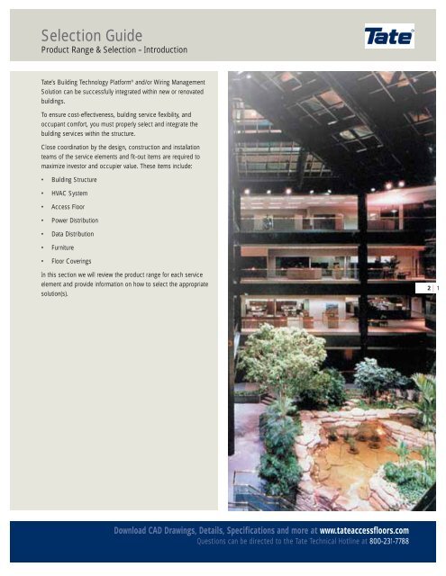
<strong>Selection</strong> <strong>Guide</strong>Product Range & <strong>Selection</strong> – Introduction<strong>Tate</strong>’s Building Technology Platform ® and/or Wiring ManagementSolution can be successfully integrated within new or renovatedbuildings.To ensure cost-effectiveness, building service flexibility, andoccupant comfort, you must properly select and integrate thebuilding services within the structure.Close coordination by the design, construction and installationteams of the service elements and fit-out items are required tomaximize investor and occupier value. These items include:• Building Structure• HVAC System• <strong>Access</strong> Floor• Power Distribution• Data Distribution• Furniture• Floor CoveringsIn this section we will review the product range for each serviceelement and provide information on how to select the appropriatesolution(s).2 | 1Download CAD Drawings, Details, Specifications and more at www.tateaccessfloors.comQuestions can be directed to the <strong>Tate</strong> Technical Hotline at 800-231-7788
<strong>Selection</strong> <strong>Guide</strong>Product Range & <strong>Selection</strong> – Introduction2 | 2Building StructureFloor to Ceiling Height ReductionsCeiling OptionsFurnitureNon-Powered WorkstationsPowered Workstations<strong>Access</strong> Floor<strong>Tate</strong> ConCore ® Panels<strong>Tate</strong> PosiLock UnderstructureModular Floor CoveringsIntroduction | <strong>Selection</strong> <strong>Guide</strong> | ConCore | All Steel | Aluminum | Wood Core | Architectural Details | Finishes<strong>Access</strong> Floor Systems | Underfloor Air Systems | Wire & Cable Systems | Summary
<strong>Selection</strong> <strong>Guide</strong>Product Range & <strong>Selection</strong> – IntroductionUnderfloor HVAC SystemsHeating/Cooling Perimeter SystemPassive and VAV DiffusersHVAC Controls2 | 3Modular Power/Cabling SystemsDistribution BoxesIn-floor PVD ServicentersPlug & Play ConnectivityDownload CAD Drawings, Details, Specifications and more at www.tateaccessfloors.comQuestions can be directed to the <strong>Tate</strong> Technical Hotline at 800-231-7788
<strong>Access</strong> Floor <strong>Selection</strong>Product Range & <strong>Selection</strong> – System Performance CriteriaImportant Load Criteria and Key FeaturesImportant criteria such as design loads and safety factors areoften over-looked when evaluating an access flooring system. Thedesign load, often referred to as the safe working load, is not thesame as a concentrated load because it includes a safety factorin the event that a panel is overloaded. This is important becauseSteelConcreteSafety Factor >2some materials used to make access floors show little or novisible damage before failing. A panel that fails without warningcan be very dangerous in the event that it is overloaded.Different materials fail in different ways. The chart belowcompares steel with concrete, two common materials used inaccess floor panels. As you can see steel will bend significantlybefore failing providing additional warning and safety.Load DefinitionsYield Point - The Yield point is the load at which permanentdamage to the system begins to occur.DEFLECTIO NYield PointDesign LoadDesign Load/Yield PointUltimate LoadUltimate Load - The maximum load that is able to be applied toa panel without failure or falling through the floor.Design Load 1 - The safe working load that can be applied to thesystem determined by choosing the smaller value of the ultimateload divided by a safety factor of two or the yield point.Safety Factor 2 - The multiple of the design load to the ultimate load.Safety Factor =21 For information on design load visit <strong>Tate</strong>’s Website and click on TechnicalResources / Technical BulletinsLO AD2 The American Society of Civil Engineers (ASCE) and The American Institute ofSteel Construction (AISC) recommend a safety factors for collapse of two.2 | 6Design FeaturesPerformancePlenumService & UsabilityKey FeaturesConCore System (Explanation and/or benefit)Panel ConstructionFlat steel top sheet welded 156 times to a waffle shape bottom sheet then filled internally with lightweight cement.Recycled Content32% recycled content, Over 10% post-consumer.Positive Engagement<strong>Tate</strong>’s PosiLock® pedestal head positions and retains panels in place without screws.Zinc WhiskersAll components of system are zinc whisker free.Combustibility*All components are noncombustible.Corner ScrewsScrews do not extend below panel underneath. Screws are designed with retention feature.Finish OptionsAlmost unlimited factory laminated finish options. PosiTile® carpet & Integral Trim® edge for HPL.Walkability*Quiet & solid underfoot with a sound transmission of 53 NNIC.Design LoadProvides a minimum safety factor of 2. Design loads are equal to or above concentrated load ratings.Overload Protection*System yields gradually for built in safety.Panel Strength Options 5 interchangeable panel strengths, meet all the requirements of a modern office building without adjustments.Cutout Strength*System maintains design load strength when cut.Air Leakage* Die cut edges reduce panel gaps (.015” +/- .005). Reduce air leakage and make it predictable .Plenum DividerAttaches to pedestals maintaining underfloor access. Adjustable to meet any width requirement.Clean Air PlenumPainted steel panels with tight seams minimize dust and debris entering the air delivery plenum.Industry Commitment<strong>Tate</strong> is the oldest and largest manufacturer dedicated solely to the R&D and marketing of access flooring.Lifting & HandlingEasy to carry with one hand an be removed with a suction cup lifter. Panels are 25% lighter than concrete panels.Shock ResistanceNo damage occurs when dropped from waist height.Cracking & ReuseSteel panels are free from unsightly cracks which improve life cycle and reuse.Edge DesignThin edge design eliminates adhesives from leaking between panels locking them place.Ease of CuttingSteel panel filled with cement cuts without special blades.Attaching WallsScrews and shot-pin can be driven directly into the panel without sacrificing it’s integrityIntroduction | <strong>Selection</strong> <strong>Guide</strong> | ConCore | All Steel | Aluminum | Wood Core | Architectural Details | Finishes<strong>Access</strong> Floor Systems | Underfloor Air Systems | Wire & Cable Systems | Summary
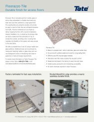
<strong>Access</strong> Floor <strong>Selection</strong>Product Range & <strong>Selection</strong> – ConCore and All Steel PanelsConCore ® PanelsAll Steel PanelsApplicationsWith five standard load performance grades and an extensiveselection of understructure supports and floor finishes, theConCore system is suitable for a wide range of applications fromgeneral office to light industrial to mission critical facilities.ApplicationsWith three standard load performance grades and completeinterchangeability with Concore, Perforated and Grate airflowpanels, these panels coupled with an extensive selection ofunderstructure supports and floor finishes are suitable for a widerange of applications from typical data/computer centers totelecommunication rooms, mission critical facilities, electronicassembly areas, and general purpose equipment applications.ConCore System Performance Criteria (Tested on Actual Understructure)Static LoadsRolling LoadsPanel Criteria(for reference only)PanelUnderstructureSystem Design Safety Factor* Uniform 10 10,000 Impact ConcentratedWeight Loads* (min. 2.0) Loads Passes Passes Loads Loads @ .100”ConCore 1000 PosiLock 7.5lbs/ft 2 1000lbs Pass 350lbs/ft 2 800lbs 600lbs 150lbs 1000lbs37kg/m 2 454kg 16.75kPa 363kg 272kg 68kg 454kgConCore 1250 PosiLock 8.5lbs/ft 2 1250lbs Pass 400lbs/ft 2 1000lbs 800lbs 150lbs 1250lbs41kg/m 2 567kg 19.1kPa 454kg 363kg 68kg 567kgConCore 1000 Bolted Stringer 9.0lbs/ft 2 1000 lbs Pass 350 lbs/ft 2 800 lbs 600lbs 150lbs 1000lbs37kg/m 2 454kg 16.75kPa 363kg 272kg 68kg 454kgConCore 1250 Bolted Stringer 10.0lbs/ft 2 1250lbs Pass 400lbs/ft 2 1000lbs 800lbs 150lbs 1250lbs49kg/m 2 567kg 19.1kPa 454kg 363kg 68kg 567kgConCore 1500 Bolted Stringer 10.5lbs/ft 2 1500lbs Pass 450lbs/ft 2 1250lbs 1000lbs 150lbs 1500lbs52kg/m 2 680kg 21.55kPa 567kg 454kg 68kg 680kgConCore 2000 Bolted Stringer 11.5lbs/ft 2 2000lbs Pass 550lbs/ft 2 1500lbs 1250lbs 150lbs 2000lbs56kg/m 2 907kg 26.3kPa 680kg 567kg 68kg 907kgConCore 2500 Bolted Stringer 12.0lbs/ft 2 2500lbs Pass 650lbs/ft 2 1500lbs 2000lbs 150lbs 2500lbs59kg/m 2 1134kg 31.1kPa 907kg 680kg 68kg 1134kgAll Steel System Performance Criteria (Tested on Actual Understructure)Static LoadsRolling LoadsPanel Criteria(for reference only)PanelUnderstructureSystem Design Safety Factor* Uniform 10 10,000 Impact ConcentratedWeight Loads* (min. 2.0) Loads Passes Passes Loads Loads @ .100”All Steel 1000 Bolted Stringer 6.0lbs/ft 2 1000 lbs Pass 350 lbs/ft 2 400 lbs 400lbs 150lbs 1000lbs30kg/m 2 454kg 16.75kPa 181kg 181kg 68kg 454kgAll Steel 1250 Bolted Stringer 7.0lbs/ft 2 1250lbs Pass 400lbs/ft 2 500lbs 500lbs 150lbs 1250lbs35kg/m 2 567kg 19.1kPa 227kg 227kg 68kg 567kgAll Steel1500 Bolted Stringer 8.5lbs/ft 2 1500lbs Pass 450lbs/ft 2 600lbs 600lbs 150lbs 1500lbs41kg/m 2 680kg 21.55kPa 272kg 272kg 68kg 680kg*Design loads and safety factors are defined in the <strong>Selection</strong> <strong>Guide</strong> Section. All other tests are conducted under CISCA’s recommended testprocedure for access floors.2 | 7Download CAD Drawings, Details, Specifications and more at www.tateaccessfloors.comQuestions can be directed to the <strong>Tate</strong> Technical Hotline at 800-231-7788
<strong>Access</strong> Floor <strong>Selection</strong>Product Range & <strong>Selection</strong> – Air Flow PanelsPerforated Panels for Equipment RoomApplicationsGrateAire ® Grates for Equipment RoomApplications2 | 8Air Flow PanelsThese panels are primarily used in applications requiring deliveryof conditioned air to equipment for the purposes of cooling theequipment. These products would typically be used in equipmentroom applications such as telecommunication switch centers,data centers, and corporate computer rooms.They are not used, nor are they recommended for, use inunderfloor air applications in commercial offices. For air deliverysolutions in Commercial Office applications, see HVAC Serviceslater in this section.Air Flow System Performance Criteria (Tested on Actual Understructure)Static loads Rolling loads Airflow (cfm)Panel TypeDesignloads*Safety factor*(min. 2.0)Uniformload10passes10,000passes.05”H 2 O.10”H 2 OPanel Criteria(for reference only)ConcentratedloadPerforated 800800 lbsPass200 lbs./ft 29.5 kPaNotrecommended552784800 lbs.363 kgPerforated 10001000 lbsPass250 lbs./ft 211.9 kPaNotrecommended5527841000 lbs.454 kgPerforated 12501250 lbsPass300 lbs./ft 214.3 kPaNotrecommended5527841250 lbs.567 kgGrateAire ®Grate1000 lbsPass250 lbs./ft 211.9 kPa1000 lbs454 kg800 lbs363 kg141620161000 lbs.454 kg*Design loads and safety factors are defined in the <strong>Selection</strong> <strong>Guide</strong> Section. All other tests are conducted under CISCA’s recommended testprocedure for access floors.Introduction | <strong>Selection</strong> <strong>Guide</strong> | ConCore | All Steel | Aluminum | Wood Core | Architectural Details | Finishes<strong>Access</strong> Floor Systems | Underfloor Air Systems | Wire & Cable Systems | Summary
<strong>Access</strong> Floor <strong>Selection</strong>Product Range & <strong>Selection</strong> – Woodcore PanelsWoodcore PanelsApplicationsWoodcore panels are available with several understructuresupport systems and numerous finishes providing a wide range ofapplications from general office environments to general purposeequipment applications such as data centers,telecommunications, and mission critical facilities.Woodcore PanelsWoodcore panels consist of high density composite wood coreglue to and encased in hot dipped galvanized formed steelsheets. These panels have a class A flame spread rating andprovide excellent rigidity, durability, and acoustic performance.Panel features• High strength to weight performance• Full range of factory finishes• Class A frame spread rating• Internally grounded• Excellent rolling load performance• Excellent acoustics• Zinc whisker free2 | 9Woodcore System Performance Criteria (Tested on Actual Understructure)Panel Criteria(for reference only)Static Loads Rolling Loads ConcentratedPanelUnderstructureSystem Design Safety Factor* Uniform 10 10,000 Impact Loads @Weight Loads* (min. 2.0) Loads Passes Passes Loads ! .010” perm setWC 5000 Cornerlock 6.9lbs/ft 2 1000lbs Pass 250lbs/ft 2 1000lbs 600lbs 150lbs 1000lbs34kg/m 2 454kg 11.9kPa 454kg 272kg 68kg 454kgSnap-tile Stringer/ 7.4lbs/ft 2 1000lbs Pass 250lbs/ft 2 1000lbs 600lbs 150lbs 1000lbsBolt-tile Stringer 36kg/m 2 454kg 11.9kPa 454kg 272kg 68kg 454kg*Design loads and safety factors are defined in the <strong>Selection</strong> <strong>Guide</strong> Section. All other tests are conducted under CISCA’s recommended testprocedure for access floors.Download CAD Drawings, Details, Specifications and more at www.tateaccessfloors.comQuestions can be directed to the <strong>Tate</strong> Technical Hotline at 800-231-7788
<strong>Access</strong> Floor <strong>Selection</strong>Product Range & <strong>Selection</strong> – Aluminum Panels2 | 10Solid Panel• Die Cast aluminum panels meet class A fire rating.• Available with a wide selection of conductive and staticdissipative coverings or coatings.• Contains no ferrous materials to disrupt magnetic fields.• Panel-to-pedestal contact ensures continuous conductivity.• Excellent rolling load performance.• Lightweight for ease of handling.• Conductive gasket ensures continuous conductivity.Grate• Designed to provide superior air flow.• Unique octagonal design reduces rolling load vibrations.• Fully interchangeable with FF1250 and FF3000 panels.• A damper can be used to regulate airflow.• Available in a variety of coatings.Perforated Panel• Perforated panels provide optimum laminar airflow, withoutturbulence.• Optional chamfered perforations provide superior particulatecontrol with up to 20% increase in airflow.• Several perforated panel patterns from which to choose.System Performance Criteria (Tested on Actual Understructure)Static LoadsRolling LoadsPanel Criteria(for reference only)PanelUnderstructureSystem Design Safety Factor* Uniform 10 10,000 Impact ConcentratedWeight Loads* (min. 2.0) Loads Passes Passes Loads Loads @ .100”FF 1250 Solid Bolted Stringer 6.5lbs/ft 2 1250 lbs Pass 400 lbs/ft 2 1000 lbs 1000lbs 150lbs 1250lbs30kg/m 2 567kg 19.1kPa 454kg 454kg 68kg 567kgFF 1250 Perforated Bolted Stringer 6.25lbs/ft 2 1250lbs Pass 400lbs/ft 2 1000lbs 1000lbs 100lbs 1250lbs35kg/m 2 567kg 19.1kPa 454kg 454kg 45kg 567kgFF 1250 Grate Bolted Stringer 7.25lbs/ft 2 1250lbs Pass 400lbs/ft 2 1000lbs 1000lbs 150lbs 1250lbs41kg/m 2 567kg 19.1kPa 454kg 454kg 68kg 567kgSystem Performance Criteria (Tested on Actual Understructure)Static LoadsRolling LoadsPanel Criteria(for reference only)PanelUnderstructureSystem Design Safety Factor* Uniform 10 10,000 Impact ConcentratedWeight Loads* (min. 2.0) Loads Passes Passes Loads Loads @ .100”FF 3000 Solid Bolted Stringer 7.6lbs/ft 2 2250 lbs Pass 750 lbs/ft 2 2000 lbs 2000lbs 200lbs 3000lbs37kg/m 2 1020kg 36kPa 907kg 907kg 91kg 1361kgFF 3000 Perforated Bolted Stringer 7.4lbs/ft 2 2000lbs Pass 750lbs/ft 2 1500lbs 2000lbs 100lbs 3000lbs36kg/m 2 907kg 36kPa 680kg 907kg 68kg 1361kg*Design loads and safety factors are defined in the <strong>Selection</strong> <strong>Guide</strong> Section. All other tests are conducted under CISCA’s recommended testprocedure for access floors. Permanent set after application of concentrated loads shall be
<strong>Access</strong> Floor <strong>Selection</strong>Product Range & <strong>Selection</strong> – Finished Floor HeightDetermine the required finished floor height• Consider the service requirementsAs part of the assessment of determining the service levels in thefloor void, consideration needs to be given to the individualrequirements at desk/operator level.As part of this exercise consider the need forexpansion/increased service levels and the implications of this onthe raised floor void and hence raised floor height.• Minimum floor to ceiling requirementsWithin any building design the top of floor to underside of ceilingminimum dimension is one aspect that is outside the designersarea of influence as it is governed by building regulations.However the use of a raised access flooring system inconjunction with under floor modular cable managementand/or under floor HVAC will allow this dimension to beoptimised (see below).• Level of services in floor voidA raised access floor is used to provide a means of creating anaccessible void which is capable of ensuring building services areavailable at their required destination. These services will typicallyinclude electrical power, data, telecom/voice, environmental/airconditioning, fire detection/suppression, security, etc.An evaluation of each of these underfloor services will give anindication of the space required for each service run. Due regardneeds to be taken for any multiple service runs, crossover ofservices, separation requirements, etc.This information can then be used to determine the cavitydepth required under the raised floor and hence the finished floorheight which will then be used in specifying the raised accessfloor system.Slab-to-Slab Floor Height ComparisonConventional Construction& Overhead HVAC SystemBuilding Technology Platform®With Underfloor HVAC2 | 11Floor slabMain structurezoneCeiling, HVAC &services zone2'0" 2'0"2'0"6"Floor slabMain structure &services zone13'6"Slab-to-slabheightcomparison13'0"Space zone9'6"9'6"Space zone1'0"Raised floor,underfloor HVAC& wire/cable zoneFloor slabFloor slabUsing the information presented on pages 12-14 will help you select the appropriate finished floor height (FFH) for your application.Download CAD Drawings, Details, Specifications and more at www.tateaccessfloors.comQuestions can be directed to the <strong>Tate</strong> Technical Hotline at 800-231-7788
<strong>Access</strong> Floor <strong>Selection</strong>Product Range & <strong>Selection</strong> – Finished Floor HeightBuilding Renovation & ModernizationApplicationsWe recommend the following finished floor heights for office andcommercial office building renovation and modernizationapplications.Retrofit for minimal impact on architectural details. Suitable forwire and cable management only. Use when floor to ceiling heightis a concern.• 2 1 /2” - 4” Finished Floor HeightThis system provides enough space under the floor to allow forvoice and data cables, as well as low profile modular wiring, up to7/8” MC cable, for use with the low profile PVD Servicenter(see the Architectural Detail section).ConCore ® /PosiLock can accommodate any floor height up toand including 24” FFH. Contact <strong>Tate</strong> Technical Support for projectspecific details.Office & Commercial Building ApplicationsWe recommend the following finished floor heights for office andcommercial building applications incorporating underfloor wireand cable management systems only.• 5” Finished Floor HeightMinimum height required for our standard height modular wiringsystem. Provides over 3 inches of space to run cable.• 6” Finished Floor HeightMinimum height required to use high capacity PVD Servicenters(see the Architectural Detail section under <strong>Access</strong>ories). For wiremanagement applications this provides enough space for fourcable crossovers of 1” MC cable.• 12” Finished Floor HeightTypical height to accommodate large amounts of cabling andpiping. Can accommodate virtually all future wiring and cablingrequirements.ConCore ® /PosiLock can accommodate any floor height up toand including 24” FFH. Contact <strong>Tate</strong> Technical Support for projectspecific details.2 | 12<strong>Tate</strong> Building RenovationPlatformBuilding Renovation UnderfloorWire & Cable Management System<strong>Tate</strong> Building WiringPlatformUnderfloor Wire & CableManagement SystemIntroduction | <strong>Selection</strong> <strong>Guide</strong> | ConCore | All Steel | Aluminum | Wood Core | Architectural Details | Finishes<strong>Access</strong> Floor Systems | Underfloor Air Systems | Wire & Cable Systems | Summary
<strong>Access</strong> Floor <strong>Selection</strong>Product Range & <strong>Selection</strong> – Finished Floor HeightOffice & Commercial Building ApplicationsWe recommend the following finished floor heights for office andcommercial building applications incorporating underfloor HVAC,wire and cable systems.• 8” Finished Floor HeightTypically the minimum height required for underfloor HVACpressurized plenums to use <strong>Tate</strong> Diffusers or VAV terminals.• 12” Finished Floor HeightFor new construction or renovation utilizing underfloor airdistribution and horizontal cable management. A minimum 12”floor height will enable you to place VAV terminals and someperimeter fan terminal units anywhere and to run cabling andpiping under these terminals if required.• 14” - 16” Finished Floor HeightTypical floor height for underfloor VAV terminals and most fanterminal units used at the building perimeter with large amountsof wiring and cabling.ConCore ® /PosiLock can accommodate any floor height up toand including 24” FFH. Contact <strong>Tate</strong> Technical Support for projectspecific details.2 | 13<strong>Tate</strong> Building TechnologyPlatform ®Underfloor HVAC, Wire & CableManagement SystemDownload CAD Drawings, Details, Specifications and more at www.tateaccessfloors.comQuestions can be directed to the <strong>Tate</strong> Technical Hotline at 800-231-7788
<strong>Access</strong> Floor <strong>Selection</strong>Product Range & <strong>Selection</strong> – Finished Floor HeightData Centers/Equipment RoomBuilding ApplicationsWe recommend the following finished floor heights for datacenters/equipment room building applications incorporatingunderfloor HVAC for equipment cooling and wire andcable systems.2 | 14• 24” - 36” Finished Floor HeightsThis provides enough space under the floor to allow for largeamounts of equipment cooling air, process piping, power wiringand data cabling. Understructure systems are available toaccommodate floor heights from 12” to 60”, however, 24” to 36”FFH are typical.Introduction | <strong>Selection</strong> <strong>Guide</strong> | ConCore | All Steel | Aluminum | Wood Core | Architectural Details | Finishes<strong>Access</strong> Floor Systems | Underfloor Air Systems | Wire & Cable Systems | Summary
<strong>Access</strong> Floor <strong>Selection</strong>Product Range & <strong>Selection</strong> – Finished Floor Height2 | 15Download CAD Drawings, Details, Specifications and more at www.tateaccessfloors.comQuestions can be directed to the <strong>Tate</strong> Technical Hotline at 800-231-7788
<strong>Access</strong> Floor <strong>Selection</strong>Product Range & <strong>Selection</strong> – Pedestal Performance CriteriaDetermine the Understructure SupportDesign type requiredVarious understructure design options are available toaccommodate structural performance requirements, floor height,and accessibility needs. It is important at an early stage in theconsideration of a raised access floor that a detailed assessmentis made of the likely loadings that will be imposed on theunderstructure. These loadings need to be assessed in terms of:• Axial Load:Axial load is a vertical load applied to the center of the pedestaldue to concentrated, rolling, uniform, and other loads applied tothe surface of the access floor panel.Axial load• Overturning Moment:Overturning moment is a lateral load applied to the pedestal dueto rolling load traffic, underfloor work due to wire pulls, or seismicactivity. It is determined by multiplying the lateral load applied tothe top of the pedestal by the pedestal’s height.A pedestal’s ability to resist overturning moment is a function ofits attachment method to the structural slab, size and thicknessof the base plate, and pedestal column size.Lateral load2 | 16• Seismic Load:Seismic load is a combination of vertical (both up and down) onthe surface of the access floor as well as lateral loads.FloorheightThe understructure system selection charts, shown on thefollowing pages outline the structural performance and heightlimitations of the <strong>Tate</strong> standard range of support pedestals. Thisallows selection of the appropriate support pedestal againststructural performance and height requirements.Note: <strong>Tate</strong> has the capacity to make a full range of pedestals tomeet virtually any criteria. For more information contact <strong>Tate</strong>Technical Hotline at 800-231-7788.Introduction | <strong>Selection</strong> <strong>Guide</strong> | ConCore | All Steel | Aluminum | Wood Core | Architectural Details | Finishes<strong>Access</strong> Floor Systems | Underfloor Air Systems | Wire & Cable Systems | Summary
<strong>Access</strong> Floor <strong>Selection</strong>Product Range & <strong>Selection</strong> – Pedestals for Steel PanelsLow Finished Floor Height PosilockBolted StringerPosiLock head2’ or 4’ stringerBolted Stringer headLFFH base:3 /4” coupling nutwelded to a 4” x4” baseType 1 base: 7 /8” squaregalvanized steel tube weldedto a 4” x 4” baseStandard Floor Height PosilockPosiLock headFeatures & BenefitsPedestal Assembly• TypeAssembly 1 base: from 2 1 7/2" to 5" FFH shall provide/8” square galvanizedsteelatube 6,000 welded lb. axial to a load without permanent deformation4” x 4” base• Assembly shall provide ± 1 /2" total adjustment with a minimumfinished floor height of 2 1 /2"• Overturning moment of 1,000 in./lbs. when <strong>Tate</strong>recommend pedestal adhesive is utilised on a cleanunsealed concrete slabFeatures & BenefitsPedestal Assembly• Assembly up to 36" FFH shall provide a 6,000 lb. axial loadwithout permanent deformation• Assembly shall provide a 2" total adjustment with a floorheight of 7" or greater• Standard finished floor heights of 6" to 36"For other finished floor heights and/or seismic conditions,please contact the <strong>Tate</strong> Technical Hotline 1-800-231-7788.• Overturning moment of 1,000 in./lbs. when <strong>Tate</strong> recommendpedestal adhesive is utilized2 | 17Understructure performance selection chartUnderstructureOverturning momentAxial loadFFH rangeReference detailsLow finished floor heightPosiLockStandard floor heightPosiLockBolted stringer1000 in-lbs.113 Nm1000 in-lbs.113 Nm1000 in-lbs.113 Nm6000 lbs.2724 kg6000 lbs.2724 kg6000 lbs.2724 kg2 1 /2” -5”64mm - 127mm5” - 24”127mm - 610mm6” - 36”152mm - 914mmConCore & All SteelSectionsConCore & All SteelSectionsConCore & All SteelSectionsDownload CAD Drawings, Details, Specifications and more at www.tateaccessfloors.comQuestions can be directed to the <strong>Tate</strong> Technical Hotline at 800-231-7788
<strong>Access</strong> Floor <strong>Selection</strong>Product Range & <strong>Selection</strong> – Pedestals for Wood Core PanelsBolt-Tite UnderstructureCornerlock UnderstructureNo. 10-32 x 3 /4”stringer screwGalvanized steel Snap-Tite stringer1/4” -20x1 7 /8” screwgalv. steel headgalv. steel headGalvanized steel stud 3 /4” -10UNCNut with vibration proof locking device7/8” sq. galv. tubing welded to4” x 4” steel baseGalvanized steel stud 3 /4” -10UNCNut with vibration proof locking deviceSnap-Tite Understructure7/8” sq. galv. tubingwelded to 4” x 4”steel base2 | 18Galvanized steel Snap-Tite stringerPanel alignment tabsFeatures & Benefitsgalv. steel headPedestal Assembly• Assembly from 2 1 /2" to 5" FFH shall provideGalvanized a 6,000 steel lb. stud axial 3 /4” load -10UNC without permanent deformationNut • with Assembly vibrationshall proof provide locking device ± 1 /2" total adjustment with a minimumfinished floor height of 2 1 /2"7/8” sq. galv. tubing welded to 4” x• 4” steel Overturning base moment of 1,000 in./lbs. when <strong>Tate</strong>recommend pedestal adhesive is utilised on a cleanunsealed concrete slabFeatures & BenefitsPedestal Assembly• Assembly up to 36" FFH shall provide a 6,000 lb. axial loadwithout permanent deformation• Assembly shall provide a 2" total adjustment with a floorheight of 7" or greater• Standard finished floor heights of 6" to 36"For other finished floor heights please contact the <strong>Tate</strong>Technical Hotline 1-800-231-7788. For seismic conditions,refer to seismic submittal details• Overturning moment of 1,000 in./lbs. when <strong>Tate</strong> recommendpedestal adhesive is utilizedUnderstructure performance selection chartUnderstructureOverturning momentAxial loadFFH rangeReference detailsBolt-TiteUnderstructureSnap-TiteUnderstructureCornerlockUnderstructure1000 in-lbs1000 in-lbs1000 in-lbs6000 lbs6000 lbs6000 lbs6” - 36”6” - 24”6” - 24”Woodcore SectionWoodcore SectionWoodcore SectionIntroduction | <strong>Selection</strong> <strong>Guide</strong> | ConCore | All Steel | Aluminum | Wood Core | Architectural Details | Finishes<strong>Access</strong> Floor Systems | Underfloor Air Systems | Wire & Cable Systems | Summary
<strong>Access</strong> Floor <strong>Selection</strong>Product Range & <strong>Selection</strong> – CoveringsType of finish on floor panels• Bare floorHere the raised floor surface will be left with its bare painted finishto accept loose laid carpet tiles by others. The panels may alsobe left with a bare painted finish to accept PosiTile ® one to onecarpet tile location system. This type of surface finish is mostsuited to office areas.When a raised access floor is used within toilet areas,cafeteria/kitchen and other potentially wet areas the floorsurface will be covered with Durarock (cement backer board) andthen covered with sheet vinyl, ceramic, or other user specifiedfloor finishes. Limited access will be provided tounder floor services in these areas but these services will notnormally require frequent access.• Factory laminated finishesThe floor covering is factory laminated to each raised accessflooring panel to give a permanently bonded finish whilemaintaining quick and easy access to the underfloor void.2 | 20Most floor coverings can be factory laminated to raised accessflooring panels to meet aesthetic and performance requirements.Edge trims are used on some surface coverings in order toprotect the edge of the covering in use. These edge trims canalso add to the architectural design and overall aesthetics of thefinished floor surface.Raised access floors finished with factory laminated staticdissipative vinyls or high pressure laminates would normally beused in computer type installations. The more exotic finishes suchas marble, stone etc would be found in areas such as receptions.Introduction | <strong>Selection</strong> <strong>Guide</strong> | ConCore | All Steel | Aluminum | Wood Core | Architectural Details | Finishes<strong>Access</strong> Floor Systems | Underfloor Air Systems | Wire & Cable Systems | Summary
<strong>Access</strong> Floor <strong>Selection</strong>Product Range & <strong>Selection</strong> – CoveringsOfficeWood Stone RubberPosiTile or Carpet TilesTerrazzo2 | 21Data Center/Equipment RoomHPL with integral trimStatic dissipative/conductive vinylDownload CAD Drawings, Details, Specifications and more at www.tateaccessfloors.comQuestions can be directed to the <strong>Tate</strong> Technical Hotline at 800-231-7788
<strong>Access</strong> Floor <strong>Selection</strong>Product Range & <strong>Selection</strong><strong>Access</strong> floor system selectionAs a general guide, selection of the appropriate system can be bygeneral description of the area. However, the guide chart shownbelow is based upon <strong>Tate</strong>’s experience to date and it isrecommended that due consideration is given to the anticipatedraised floor loadings and height requirements in every case.System selection guide chartPanel typeBuilding typeStandardHeavyUnderstructure typeGeneral OfficeConCore ® 1000ConCore ® 1250PosiLockService CorridorsConCore ® 1500ConCore ® 2000ConCore ® 2500Combination BoltedStringer & CornerLockComputer RoomsConCore ® 1000All Steel 1250Perforated 1000Woodcore 5000ConCore ® 1250Perforated 1250Bolted StringerInternetData Center/Telecom SwitchConCore ® 1000All Steel 1250GrateAire ®ConCore ® 1250GrateAire ®Bolted Stringer2 | 22Clean RoomFF1250 Solid, Perfs & GratesFF3000 Solid, Perfs & GratesBolted StringerElectrical/Telecom ClosetConCore ® 1000All Steel 1250ConCore ® 1250Bolted StringerLobbiesConCore ® 1500ConCore ® 2000ConCore ® 2500Combination BoltedStringer & CornerLockCasinosConCore ® 1500ConCore ® 2000ConCore ® 2500Combination BoltedStringer & CornerLockEducationalConCore ® 1000ConCore ® 1250PosiLockPrint RoomsConCore ® 1500ConCore ® 2000ConCore ® 2500Bolted StringerCall CentersConCore ® 1000ConCore ® 1250PosiLockTrading <strong>Floors</strong>ConCore ® 1250ConCore ® 1500Bolted StringerRetailConCore ® 1000ConCore ® 1250PosiLockIntroduction | <strong>Selection</strong> <strong>Guide</strong> | ConCore | All Steel | Aluminum | Wood Core | Architectural Details | Finishes<strong>Access</strong> Floor Systems | Underfloor Air Systems | Wire & Cable Systems | Summary
<strong>Access</strong> Floor <strong>Selection</strong>Product Range & <strong>Selection</strong>Finished Floor HeightWire/cable onlyWire/cable & airCoveringsReference specifications2 1 /2” –6”12” – 18”Carpet TilePosiTile ®Speciality CoveringsConCore Section2 1 /2” –6”12” – 18”HPL with Integral TrimRubber TileConCore Section12” – 24”24” – 36”HPL with Integral TrimConCore, All Steel & Woodcore12” – 24”24” – 36”HPL with Integral TrimConCore & All Steel Sections18” – 24”24” – 36”HPL with Integral TrimConductive Vinyl with TrimAluminum Section2 | 236” – 12”N/AHPL with Integral TrimConCore & All Steel Sections2 1 /2” –6”12” – 18”Carpet TilePosiTile ®Speciality CoveringsConCore Section6” – 12”12” – 18”Carpet TilePosiTile ®Speciality CoveringsConCore Section2 1 /2” –6”12” – 18”Carpet TilePosiTile ®VinylConCore Section6” – 12”12” – 18”Vinyl TileRubber TileConCore Section6” – 18”12” – 18”Carpet TilePosiTile ® TileConCore Section6” – 12”12” – 24”Carpet TilePosiTile ® TileConCore Section2 1 /2” –6”12” – 18”VinylSpeciality CoveringsConCore SectionDownload CAD Drawings, Details, Specifications and more at www.tateaccessfloors.comQuestions can be directed to the <strong>Tate</strong> Technical Hotline at 800-231-7788
<strong>Access</strong> <strong>Floors</strong>Product Range & <strong>Selection</strong> – Glossary of Terms2 | 24Building Technology Platform ® (BTP)A service distribution system consisting of an access floor withunderfloor modular wiring complete with floor terminations,electrical boxes and modular underfloor HVAC system.<strong>Access</strong> Floor (A/F)Refers to the entire access flooring system including panels,pedestals and accessories.Finished Floor Height (FFH)Dimension measured from the subfloor surface to the top surfaceof the access floor panel.PedestalStructural element with leveling capability designed to elevate theaccess floor panel to a desired height.PosiLockA pedestal designed to provide positive access floor panelpositioning and lateral containment with or without the useof fasteners.StringerStructural element designed to horizontally connect one pedestalto another to gain additional lateral stability.Understructure (U/S)<strong>Access</strong> floor panel’s structural supporting elements generallyconsisting of pedestals and where needed, stringers andfasteners.<strong>Access</strong> Floor PanelStructural load bearing element typically 2’ x 2’ square designedto be supported by pedestals.ConCore ®<strong>Access</strong> floor panel constructed with steel top plate welded tosteel formed bottom plate and filled internally with lightweightcement material.PosiTile ®Carpet tile that is the same size as an access floor panel andcomes complete with positioning buttons designed to index tile topanel without adhesive. Typically used in office applications.High Pressure Laminate (HPL)A floor finish typically used in equipment room application.Consists of resin and paper with various printed paper patternscomplete with melemine clear surface for maximum durability.Integral TrimEdge treatment for high pressure laminate providing protectionagainst edge chipping, and eliminating the need for a separatetrim piece.DeflectionThe amount of movement exhibited by an access floor panelwhen a load is applied to its surface.Permanent SetThe amount of residual deflection left in the access floor panelwhen a load is removed from its surface.Local DeformationLocal deformation is generally the term used when referring to thelocalized permanent set recorded along the wheel path after arolling load test. ItDynamic LoadLoads that vary significantly with time as measurements are beingmade. Two examples of dynamic loads are rolling loads andimpact loadsStatic LoadA static load is a force which does not undergo a change inmagnitude or direction during a measurement procedure. Threestatic loads generally referred to are concentrated, ultimate, anduniform loads.Live LoadA live load is produced by the use or occupancy of a building.this does not include construction, environmental, seismic, oraccess floor dead loads. The live load should not be confusedwith the uniform load capacity of an access floorDesign LoadThe safe working load that can be applied to the systemdetermined by choosing the smaller value of the ultimate loaddivided by a safety factor of two, or the yield point.Introduction | <strong>Selection</strong> <strong>Guide</strong> | ConCore | All Steel | Aluminum | Wood Core | Architectural Details | Finishes<strong>Access</strong> Floor Systems | Underfloor Air Systems | Wire & Cable Systems | Summary
HVAC ServicesProduct Range & <strong>Selection</strong> – Introduction2 | 25Download CAD Drawings, Details, Specifications and more at www.tateaccessfloors.comQuestions can be directed to the <strong>Tate</strong> Technical Hotline at 800-231-7788
HVAC ServicesProduct Range & <strong>Selection</strong> – IntroductionOverhead Constant Volume (CV) SystemThe typical method of air distribution throughout the 1960’s was aconstant volume system (CV). With this system, a constantvolume of conditioned air was supplied to a space. Zone controlwas accomplished by adding heat to this airstream to satisfy thethermostat, and prevent a space from overcooling.Corporate Headquarters – Jessup, Maryland, USASeveral problems existed with these systems. First, the heatingand cooling plant, as well as the air distribution system, neededto be sized to handle the total load of the building without beingable to take advantage of the load diversity occurring in thespace. This added considerably to the first cost of the system.Secondly, this type of system mixed hot and cold and thereforewas not energy efficient.Constant Volume Overhead HVAC DistributionCooling coilConstant speed supply fanFiltersReheat coil(electric, hot water, steam)Control dampersOutside air inletThermostat90°/90% RHReturn air inletSupply diffuser2 | 26Return airgrille55°75°/50% RH55-80° 55-80°4'2 | 2610'• Even distribution of temperature and pollutantsthroughout space• Supply air ‘short circuiting’• Supply air fan runs at a constant speed, regardlessof load• Supply air is reheated to satisfy space comfortIntroduction | <strong>Selection</strong> <strong>Guide</strong> | ConCore | All Steel | Aluminum | Wood Core | Architectural Details | Finishes<strong>Access</strong> Floor Systems | Underfloor Air Systems | Wire & Cable Systems | Summary
HVAC ServicesProduct Range & <strong>Selection</strong> – IntroductionOverhead Variable Air Volume (VAV) SystemDuring the late 1960’s and into the early 1970’s, a new type ofsystem began to take hold of the market, and there began aparadigm shift in the Heating, Ventilation and Air Conditioning(HVAC) industry. This new system was the Variable Air Volume(VAV) system. The basic principle of this system is to vary theamount of constant temperature air to a zone to satisfy thecooling load. The benefits of this system are the ability to takeadvantage of the diversity of cooling loads within a building. Thisallows the designer to downsize both equipment and ductsystems, by as much as 30% or more, depending on the facility.Along with the first cost savings, energy usage is reducedsignificantly, since mechanically cooled air is not being re-heated,and fan horsepower is reduced.All commercial buildings experience diversity. Buildings that havea traditional occupancy (buildings with a constant number ofWNSEpeople for specific, fixed hours) stillexperience diversity. Solar loads are themost common diverse loads, butcontinually through the day, people aremoving from space to space, shifting thecooling load between zones. A properlydesigned HVAC system will be able totrack and accommodate this movementof load.Heat is normally only applied at theperimeter of a building with a VAV system.Perimeter spaces can be enclosed with ahard wall, or can be part of an open plan office area.VAV continued for 30 years through to the end of the century asthe most popular way to air condition commercial buildings andmany industrial applications.Variable Volume Overhead HVAC DistributionVariable speed supply fanVAV terminalCooling coilFiltersControl dampersOutside air inlet2 | 27ThermostatSupply diffuser90°/90% RHReturn air inletReturn airgrille55°55° 55°75°/50% RH4'10'• Even distribution of temperature and pollutantsthroughout space• Supply air ‘short circuiting’• Large amount of ductwork required• VAV operation only supplies enough air to satisfy comfort andreduces fan energy• Distribution duct, air handling unit and chiller can bedownsized to take advantage of building coolingload diversityDownload CAD Drawings, Details, Specifications and more at www.tateaccessfloors.comQuestions can be directed to the <strong>Tate</strong> Technical Hotline at 800-231-7788
HVAC ServicesProduct Range & <strong>Selection</strong> – IntroductionMigration of Technology into the Workplace:A Switch to Underfloor Air DistributionBuilding infrastructure needs since the mid-1980’s have evolvedsignificantly. With the advent of the desktop computer, computernetworks, printers, copiers and fax machines, the need for power,voice and data cabling has risen dramatically. Management ofthese wiring systems has become an issue. More and morefacilities are being built with a raised access floor to house andaid in the management of this cabling. A raised access flooroffers significant flexibility and ease of management of thesecabling systems along with cost savings. The same flexibility canbe added to the HVAC System when the void created by theaccess floor is used for air distribution.• Underfloor Air Distribution SystemUnderfloor Air Distribution (UFAD) has been used in Europe andSouth Africa for a number of years. This concept is gainingpopularity in the United States. UFAD delivers air from the spacebelow the access floor through either passive diffusers withmanual volume and direction control or VAV thermostaticallycontrolled devices. Delivering air from the floor offers addedbenefits, beyond rearrangement flexibility. Cool, clean air isdelivered directly into the occupied zone of the space, so heatand pollutants are not continually circulated within the space asthey are with an overhead system. The result is a space that hasstratification of heat and pollutants, with concentrations in thelower levels of the space less than those at the upper levels ofthe space. Ventilation is accomplished through displacement asopposed to dilution. Also, since the pressure required to supplyair to the space is significantly less compared to an overheadsystem, fan energy usage can be reduced.Underfloor HVAC DistributionVariable speed supply fanCooling coilFiltersControl dampersOutside air inlet2 | 2890°/90% RHFilterReturn air bypassReturn air grille 82°60°2'80°78° – 8'10'60°77° – 6'75° – 3'72° – 3"VAV or Passive Diffuser<strong>Access</strong> floor 12" FFH• Stratification of heat and pollutants• Better Indoor Air Quality (IAQ) in breathing zone• Use of bypass air for free reheat• Modular VAV or passive diffusers• Low pressure plenum reduces fan energy• Distribution duct, air handling unit and chiller can bedownsized to take advantage of building cooling loaddiversityIntroduction | <strong>Selection</strong> <strong>Guide</strong> | ConCore | All Steel | Aluminum | Wood Core | Architectural Details | Finishes<strong>Access</strong> Floor Systems | Underfloor Air Systems | Wire & Cable Systems | Summary
HVAC ServicesProduct Range & <strong>Selection</strong> – IntroductionUFAD – how does it workUnderfloor Air Distribution System is a floor based system.The space that houses the power, voice and data cabling ispressurized with space conditioning air.The pressure requirement of the system is 0.05” - 0.10” w.g.static pressure. Supply air used to pressurize the space isnominally 60º F. In order to maintain humidity control in the supplyair, the air is cooled to 52º-55º F, and then mixed with return air to60º F, or higher. The system utilizes a bypass of return air fromthe space, mixing it with saturated air from the cooling coil, priorto discharging it to the supply air plenum. Only return air from thespace bypasses the coil. If a mixture of outdoor air and return airbypasses the coil, a loss of humidity control may result, so astandard face and bypass coil configuration will not suffice.Load Calculation ConsiderationsCooling Loads are considered somewhat differently than they arewith an overhead VAV system.Building cooling loads are comprised of all pieces of equipment,or occupants in the building that generate heat. They alsoinclude the effects of weather outside of the building. An HVACdesigner will look at cooling loads from two points of view.Internal loads are comprised of the people, overhead lighting andsmall power (computers, equipment) in a building. External loadsare the effects of weather on the building (solar load, heattransmission, infiltration).The primary difference of the underfloor and overhead systems ishow these cooling loads are accounted for in the air conditioningsystem. With the UFAD System, we are only air conditioning thelower 6’ (occupied zone) of the space. An overhead systemconditions the entire space from floor to ceiling. With an overheadsystem, the temperature from the floor to the ceiling is nearlyconstant. With the UFAD system, there is a temperature gradientfrom the floor to the ceiling. This is one of the key differentiatingfactors when calculating system sizes.Overall, in typical buildings, airflows to the space are slightly lesswith the UFAD system, and chiller or refrigeration capacity is less.Of course every building is different, and there are many factorsthat effect the calculation of cooling loads. Precise loadcalculations should be performed for each building design.Underfloor HVAC Distribution2 | 29Variable speed supply fanCooling coilFiltersControl dampersOutside air inlet90°/70% RHFilterReturn air bypassReturn air grille 82°60°2'80°78° – 8'10'60°77° – 6'75° – 3'72° – 3"VAV or Passive DiffuserTerminal (MIT)<strong>Access</strong> floor 12" FFHDownload CAD Drawings, Details, Specifications and more at www.tateaccessfloors.comQuestions can be directed to the <strong>Tate</strong> Technical Hotline at 800-231-7788
HVAC ServicesProduct Range & <strong>Selection</strong> – BenefitsVariable Air Volume Overhead HVAC Distribution:• Heat and pollutants evenly distributed throughout spaceVariable speed supply fanVAV terminalCooling coilFiltersControl dampersOutside air inletThermostatSupply diffuser90°/90% RHReturn air inletReturn air grille55°55° 55°75°/50% RH4'10'2 | 30Underfloor Air Distribution• Heat and pollutants concentrated at ceiling away frombreathing zone• Ventilation air enters breathing zone firstVariable speed supply fanCooling coilFiltersControl dampersOutside air inlet90°/90% RHFilterReturn air bypassReturn air grille 82°60°2'80°78° – 8'10'60°77° – 6'75° – 3'72° – 3"VAV or Passive Diffuser<strong>Access</strong> floor 12" FFHIntroduction | <strong>Selection</strong> <strong>Guide</strong> | ConCore | All Steel | Aluminum | Wood Core | Architectural Details | Finishes<strong>Access</strong> Floor Systems | Underfloor Air Systems | Wire & Cable Systems | Summary
HVAC ServicesProduct Range & <strong>Selection</strong> – BenefitsBenefits of Underfloor Air (continued)Energy Saving OpportunitiesThere are several areas where energy savings can be takenadvantage of with an underfloor air distribution system, whencompared to a variety of traditional systems. As with any HVACsystem, care must be taken to properly size the equipment forit’s intended use. Following are several suggestions that will aidthe designer in making the correct decision on the equipment tobe installed.Fan EnergySince the static pressure requirements of the underfloor plenumare only 0.05” – 0.10” w.g., compared to 1.5” – 2.0” w.g. for anoverhead VAV system, supply air fan horsepower can besignificantly reduced.Ventilation Air RequirementsSince the ventilation effectiveness with underfloor air is greaterthan that of an overhead system, the facility designer has severalchoices. The first would be to supply the same amount ofventilation air to the space, improving the indoor environment forthe occupants. The second opportunity may be to lower theamount of ventilation air supplied to the space, maintaining thesame indoor air quality, but lowering operating costs.Chiller savingsThere are two areas of savings with equipment selections, one isan initial cost savings, and the other is an energy-based savings.• As previously mentioned, operating the system usingventilation air reset can save operating costs, based on CO 2levels in the occupied spaces.• Using the thermal storage capacity of the floor slab, coolingthe slab overnight with economizer or free cooling, and takingadvantage of the stored energy during the day may result inthe ability to save energy.• A smaller supply air fan and motor will generate less heat thatneeds to be removed by the system. This is a direct capacityand energy savings.• The return air to the Air Handling unit (AHU) is typically in therange of 80º-84ºF. This means that any exhaust air from thebuilding will take with it more heat from the space, comparedto an overhead system returning 76ºF. air. This is a directcapacity and energy saving.• If we size the number of terminals to cool the interior spaceusing 65º F. supply air, we can take advantage of free cooling,or economizer operation for more hours of the year. This canbe used in areas that have appropriate humidity conditions,but the savings can be substantial. Figure #5 below indicatesthe number of additional hours of free cooling potential for anumber of cities across the United States.• Due to stratification in the space, the temperature is higher atthe ceiling, compared to a traditional overhead system.Temperatures at the ceiling will be in the range of 80º-82º F atthe skin of the building. This results in less transmissionthrough the skin in the stratified zone of the space allowingfor capacity and energy savings.2 | 31Figure: 5Annual weather dataCity Hours < 55°F Hours 55°-65°F % Additional hoursNew York City 3842 780 20%Chicago 3619 604 17%St. Louis 4754 586 12%Atlanta 5779 773 13%Dallas 6199 645 10%San Francisco 5235 1593 30%Download CAD Drawings, Details, Specifications and more at www.tateaccessfloors.comQuestions can be directed to the <strong>Tate</strong> Technical Hotline at 800-231-7788
HVAC ServicesProduct Range & <strong>Selection</strong> – BenefitsBenefits of Underfloor Air (Continued)CostThe cost of an underfloor air system is typically less than theinstalled cost of a traditional overhead VAV system.• A significant portion of ductwork is eliminated, including all ofthe overhead ductwork in most instances.required, and no underfloor plenum partitions need to berelocated.• Creating a new zone, or making a large zone into severalsmaller zones is accomplished by adding a few plug and playcontrol components. Again, no ductwork or plenum partitionreconfiguration.• Installation is done on the floor, not on ladders or scaffolding.• The cost of field modifications is nearly eliminated. If aterminal needs to be relocated prior to occupancy, it can bemoved in several minutes. No ductwork modifications arerequired to accomplish this.• Reconfiguration of zones is a matter of rearranging the plugand play control wiring. No ductwork modifications are2 | 32Introduction | <strong>Selection</strong> <strong>Guide</strong> | ConCore | All Steel | Aluminum | Wood Core | Architectural Details | Finishes<strong>Access</strong> Floor Systems | Underfloor Air Systems | Wire & Cable Systems | Summary
HVAC ServicesProduct Range & <strong>Selection</strong> – Interior Components• Passive DiffuserPassive diffusers are modular devices that are designed to mountinto an access floor and “plug” into the underfloor air handlingspace. This device delivers conditioned air at floor level to thespace and allows the occupant to manually control both thevolume and direction of the air.• Interior – VAV DiffuserVAV diffusers are modular devices that are designed to mountinto an access floor and “plug” into the underfloor air handlingspace. This device delivers conditioned air at floor level to thespace and is controlled by a thermostat.2 | 33Note: Product components pictured are manufactured by York International a Johnson Controls Company.Download CAD Drawings, Details, Specifications and more at www.tateaccessfloors.comQuestions can be directed to the <strong>Tate</strong> Technical Hotline at 800-231-7788
HVAC ServicesProduct Range & <strong>Selection</strong> – Perimeter Components• Perimeter - Fan Terminal Unit (cooling mode)The perimeter fan terminal unit is designed to deliver bothcooling and heating to the space. In cooling mode, the sidedampers of the device open to allow conditioned air to exitout of both diffusers.2 | 34• Perimeter - Fan Terminal Unit (heating mode)The perimeter fan terminal unit is designed to deliver both coolingand heating to the space. In heating mode, the dampers closeand the fan energizes to draw-in room air through one diffusersending it through an electric or hot water coil and then exit thewarm air out the other diffuser.Note: Product components pictured are manufactured by York International a Johnson Controls Company.Introduction | <strong>Selection</strong> <strong>Guide</strong> | ConCore | All Steel | Aluminum | Wood Core | Architectural Details | Finishes<strong>Access</strong> Floor Systems | Underfloor Air Systems | Wire & Cable Systems | Summary
HVAC ServicesProduct Range & <strong>Selection</strong> – Perimeter Components• Perimeter - Trough Style Unit (cooling mode)The trough style unit is designed to deliver both cooling andheating to the space. In cooling mode, the dampers open toallow conditioned air to exit out of the linear bar grill.Fin Tube OffAir PlenumDamper Open• Perimeter - Trough Style Unit (heating mode)The trough style unit is designed to deliver both cooling andheating to the space. In heating mode, the dampers close andthe fin tube energizes and heats up. The cool air from theperimeter glass travels down one side of the trough and warm airmoves out into the space through the other side of the trough.2 | 35Fin Tube OnAir PlenumDamper ClosedDownload CAD Drawings, Details, Specifications and more at www.tateaccessfloors.comQuestions can be directed to the <strong>Tate</strong> Technical Hotline at 800-231-7788
Wire & Cable ServicesProduct Range & <strong>Selection</strong> – Introduction2 | 36Introduction | <strong>Selection</strong> <strong>Guide</strong> | ConCore | All Steel | Aluminum | Wood Core | Architectural Details | Finishes<strong>Access</strong> Floor Systems | Underfloor Air Systems | Wire & Cable Systems | Summary
Wire & Cable ServicesProduct Range & <strong>Selection</strong> – IntroductionBackground• Types of wiringThere are a variety of wiring types for distributing power from theservice closet to the point of use. Methods ranging from highlyflexible pre-connectorized manufactured wiring to labor intensivefield installed conduit and hard wired terminations.Rigid Conduit with Hard Wired ConnectionsFlexible Conduit with Hard Wired Connections2 | 37Manufactured Modular Wiring with ‘Plug and Play’ ConnectionsDownload CAD Drawings, Details, Specifications and more at www.tateaccessfloors.comQuestions can be directed to the <strong>Tate</strong> Technical Hotline at 800-231-7788
Wire & Cable ServicesProduct Range & <strong>Selection</strong> – Introduction• Wire and cable distributionThe wiring types discussed on previous page as well asvoice/data and other cabling can be routed to the point ofuse in many ways. These include running wire and cabling underan access floor, down through walls, in ceiling space anddown through power poles or up through poke-through fittingsfor example.Conventional Wiring SystemWiring for power distribution topowered furniture via power polesLow voltage voice/data cablingcontained in cable trays and fedto workstation via power poles2 | 38Wiring for power distribution to poweredfurniture via through slab ‘poke-through’s’Wiring for power distribution to servicesembedded into walls/partitionsModular Wiring SystemPVD Servicenter‘Plug and Play’ connectorPower wiring and low voltage voice/datacabling routed under access floor<strong>Access</strong> FloorIntroduction | <strong>Selection</strong> <strong>Guide</strong> | ConCore | All Steel | Aluminum | Wood Core | Architectural Details | Finishes<strong>Access</strong> Floor Systems | Underfloor Air Systems | Wire & Cable Systems | Summary
Wire & Cable ServicesProduct Range & <strong>Selection</strong> – Introduction• Flexibility and accessibility requirementsWhen distributing wire and cabling to the point of use,consideration to the degree of accessibility and flexibility shouldbe given. This requires proper selection of both wiring typesand distribution methods as providing the wrong combinationmay likely cause a failure to meet the desired flexibility andaccessibility requirements.Expensive cable traysrequired to suspend androute cabling in ceilingConduit and wiring consists of fixedpiping and hard wired connectionswhich are inflexible and laborintensive to install and relocateJunction box for hardwired connectionsPower pole capacity to handlewiring/cabling is greatly limitedReconfiguration/relocation of wiringdifficult due to wiring/servicesembedded into wall fabric andconsists of fixed piping and hardwired connections2 | 39Reconfiguration/relocationdifficult due to need to accesswiring/cabling in ceiling usingladders and is routed andembedded in furnitureReconfiguration/relocationdifficult due to need to accesswiring/cabling from floor belowDownload CAD Drawings, Details, Specifications and more at www.tateaccessfloors.comQuestions can be directed to the <strong>Tate</strong> Technical Hotline at 800-231-7788
Wire & Cable ServicesProduct Range & <strong>Selection</strong> – Introduction• Best Practice – Service Distribution SystemThe Building Technology Platform ® provides the most flexibleand accessible wire and cable distribution system. It doesthis by combining a wire/cable distribution system that isaccessible at any location on the floor plate (<strong>Access</strong> Flooring) witha highly flexible ‘plug and play’ wiring system (ManufacturedModular Wiring and Cabling).PVD ServicenterLow voltage voice/data cabling‘Plug and Play’ Modular Wiring<strong>Access</strong> Floor2 | 40Introduction | <strong>Selection</strong> <strong>Guide</strong> | ConCore | All Steel | Aluminum | Wood Core | Architectural Details | Finishes<strong>Access</strong> Floor Systems | Underfloor Air Systems | Wire & Cable Systems | Summary
Wire & Cable ServicesProduct Range & <strong>Selection</strong> – Modular Wiring and CablingManufactured Modular Wiring and Cabling• What is it, and why should I use it?Manufactured Modular Wiring is a pre-fabricated,pre-assembled, and pre-packaged power distribution systemconsisting of copper conductors encased in flexible metal conduitand terminated at the ends with plug together connectors.PowerBreakerPanelTelecomRackHome RunCableMainDistributionBoxDataPowerExtenderCablePowerExtenderCablePVDServicenterZoneDistributionBoxThermostatVariable AirVolumeTerminal (VAV)2 | 41VoicePCM(24 volt)Modular Wiring flexibility‘Plug and Play’ connectivityDownload CAD Drawings, Details, Specifications and more at www.tateaccessfloors.comQuestions can be directed to the <strong>Tate</strong> Technical Hotline at 800-231-7788
Wire & Cable ServicesProduct Range & <strong>Selection</strong> – Modular Wiring and Cabling• ‘Plug and Play’ at work: FlexibilityModular wiring’s highly flexible wiring and plug connectionscombined with access floor’s accessibility enables reconfigurationof services to be fast, easy, and cost effective.PVD Servicenter*access floor boxPower Distribution Module* Moving floor service box requires unplugging, removal of panel to new location and replugging back in – no waste, quick and easy!2 | 42• Hard wired: inflexibilityWhereas it is acceptable to use conduit and hard wiredconnections under an access floor, the inflexibility of the wiringmakes moving services more time consuming and costly.Hard wired connectionFloor service box*electrical/dataterminationJunction boxConduit* Moving floor service box requires abandoning existing conduit line and installing new line with junction box. Additionally requiresdisconnection of service box and rewiring to new junction box.Therefore whenever possible, use modular wiring to distributepower under an access floor to maintain the system’s flexibilityand cost effectiveness.Introduction | <strong>Selection</strong> <strong>Guide</strong> | ConCore | All Steel | Aluminum | Wood Core | Architectural Details | Finishes<strong>Access</strong> Floor Systems | Underfloor Air Systems | Wire & Cable Systems | Summary
Wire & Cable ServicesProduct Range & <strong>Selection</strong> – Modular WiringModular Wiring – The ComponentsThe main components of a manufactured modular wiringsystem are:• Home Run Cable• Power Distribution Module• Power Cable• Homerun CableThe home run cable consists of flexible metal conduit completewith conductors and is designed to provide power from theservice closet to the Power Distribution Module. The cable isgenerally factory wired to a Power Distribution Module or it isfactory terminated with a ‘plug and play’ connector.• Power Distribution ModuleThe Power Distribution Module (PDM) is a modular powerdistribution center that can distribute any combination of up to 18circuits across multiple ports. Pre-wired and tested at the factory,the PDM’s are configured to meet any project requirements.PDM’s are connected by ‘plug and play’ extender cables to PVDServicenters.2 | 43• Power CablesThe transition cable consists of flexible metal cable with ‘plug andplay’ connectors on either end. It can be used anywhere alongthe entire length of the system. It is designed to provide power todevices equipped with modular connectors.The component drawings depict product manufactured by Communications Integrators, Inc. (Cii) www.ciinet.comDownload CAD Drawings, Details, Specifications and more at www.tateaccessfloors.comQuestions can be directed to the <strong>Tate</strong> Technical Hotline at 800-231-7788
Wire & Cable ServicesProduct Range & <strong>Selection</strong> – Modular CablingZone Cabling – The ComponentsThe main components of a manufactured modular wiringsystem are:• Passive Zone Distribution Box• Active Zone Distribution Box• Plug and Play Cables• Passive Zone Distribution BoxThe passive zone distribution box is a modular cableconsolidation point that can house up to 96 cable connections.The consolidation point provides an intermediate connection fromthe distribution box to the PVD Servicenter.2 | 44• Active Zone Distibution BoxThe active zone distribution box is a modular cable consolidationpoint that allows for a major reduction in the amount of horizontalcable. this is accomplished by bringing fiber into the box and thenexiting with short run copper cable to the PVD Sevicenters.Chatsworth accessfloor fiber box• Plug & Play CablesPlug & play cables consist of low voltage cabling with connectorson either end and can be used along the entire length of thesystem. These cables are designed to provide voice/data todevices with modular plug & play connectivity.The component drawings depict product manufactured by Communications Integrators, Inc. (Cii) www.ciinet.comIntroduction | <strong>Selection</strong> <strong>Guide</strong> | ConCore | All Steel | Aluminum | Wood Core | Architectural Details | Finishes<strong>Access</strong> Floor Systems | Underfloor Air Systems | Wire & Cable Systems | Summary
Wire & Cable ServicesProduct Range & <strong>Selection</strong> – PVD Servicenter<strong>Tate</strong> PVD Servicenter <strong>Access</strong> Floor Service BoxThe access floor service box is designed to terminate powerwiring at floor level and provide convenient user access toelectrical outlets. The box contains a hinged lid with recess for afloor finish insert designed to match surrounding finish formaximum aesthetic appeal. Floor service boxes are installedwithin an access floor panel and can be relocated at any point onthe floor plate. Low voltage wiring is accommodated in the floorbox by either terminating in the box with interface plates or simplythrough grommeted openings for convenient pass through.<strong>Access</strong> Floor Service Boxes are available in several configurationsto handle both capacity needs and finished floor heightrequirements.• Standard Floor Height, High Capacity PVD Servicenter– For floor heights 6” or higher– Accommodates up to four duplex receptacles, and has upto three openings to accommodate industry standard voiceand data plates or grommeted cable pass-through opening–11 1 /4” square maximizes outlet space and hand room– Hinged lid accommodates carpet or vinyl insert to blendwith the floor finish– Compatible with Modular Wiring connectors or hardwired connections• Low Floor Height, High Capacity PVD Servicenter– For floor heights 2 1 /2” -6”– - Accommodates up to two duplex receptacles, and twovoice and data ports, and one grommeted cable passthroughopening–11 1 /4” square maximizes outlet space and hand room– Hinged lid accommodates carpet or vinyl insert to blendwith the floor finish– Compatible with Modular Wiring connectors or hardwired connections2 | 45• Standard Floor Height, Standard CapacityPVD Servicenter– For floor heights 6” or higher– Accommodates up to two duplex receptacles, and twomultiport interface plates for voice/data terminations– Smaller lid dimensions of 7” x 8” but with the same featuresas a larger lid providing a family appearance– Compatible with Modular Wiring connectors or hardwired connectionsDownload CAD Drawings, Details, Specifications and more at www.tateaccessfloors.comQuestions can be directed to the <strong>Tate</strong> Technical Hotline at 800-231-7788
SummaryProduct Range & <strong>Selection</strong> – Building Systems Integration2 | 46To ensure maximum building service flexibility, occupant comfort,and cost effectiveness, building services must be properlyintegrated within the structure. The following checklist includesfactors to consider in applying the Building Technology Platform ®solution to your building.Evaluation Checklist:<strong>Access</strong> Floor• The access floor should have a minimum finished floor heightof 8” (recommended floor height of 12”) to provide adequatespace for power, voice, data wiring, and underfloor air.• When utilized for wire and cable service distribution only, aminimum finished floor height of 4” is advised.• The access floor should be structurally sound, capable ofhandling both static and rolling loads with a minimum designload safety factor of two.• The access floor should be solid and quiet, free of rattlesand squeaks.• It should be dimensionally consistent with minimalgaps to control air leakage.• It should provide a +/-1” leveling adjustment capability toaccommodate uneven sub-floors.• It should be noncombustible and capable of accommodatingan environmental air handling space.• It should be compatible with a wide range of commonlyused floor finishes.• It should be simple and cost effective to accessand reconfigure.• It should be lightweight, easy to cut and capable ofaccommodating a variety of load conditions.HVAC System• The HVAC system should include minimal ductwork for costeffectivemaintenance and reconfiguration.• It should include modular diffusers in the access floor panelsfor easy access and reconfiguration.• It should be designed to condition air only in the occupants’zone and allow the rest of the space to stratify for energyefficiency.• It should provide fresh, clean air at floor level, improvingventilation effectiveness, energy, and air quality superior tooverhead systems.• It should operate at 0.05” – 0.10” w.g. vs. overhead 1 - 2”static pressure, saving significant fan energy.• It should utilize VAV technology to cost effectively andefficiently handle load diversity in the space.• It should be factory pre-manufactured with ‘plug and play’connectivity, allowing faster installation, earlier occupancy.• It should provide simple pre- and post constructionreconfiguration capability, eliminating need for specializedmaintenance personnel.• It should be coordinated with other building services uponinstallation, before access floor installation.Electrical Distribution• The electrical distribution system should utilize ‘plug and play’wiring, allowing quick and easy reconfiguration.• It should be factory pre-manufactured, fullypre-connectorized allowing faster installation, earlieroccupancy.• It should provide simple pre- and post constructionreconfiguration capability, eliminating need for specializedmaintenance personnel.• The electrical distribution system should terminate wiring atfloor level using Floor Service Box, eliminating the need forcostly powered office furniture.• It should be coordinated with other building services uponinstallation, before access floor installation.Low Voltage Cabling Distribution• The low voltage cabling distribution system should be placedunder an access floor for optimum accessibility andreconfiguration.• It should terminate cabling at floor level using Floor ServiceBox to increase flexibility of the furniture system.• It should utilize ‘plug and play’ cabling for maximum flexibilitywhere possible.• It should be coordinated with other services upon installation,before access floor installation.Introduction | <strong>Selection</strong> <strong>Guide</strong> | ConCore | All Steel | Aluminum | Wood Core | Architectural Details | Finishes<strong>Access</strong> Floor Systems | Underfloor Air Systems | Wire & Cable Systems | Summary
SummaryProduct Range & <strong>Selection</strong> – Building Systems IntegrationCeiling System• When using underfloor service distribution, the suspendedceiling height space can be reduced due to elimination ofductwork and wiring in the ceiling.• Depending on acoustic requirements, suspended ceilingmay be eliminated partially or entirely, resulting in greaterdesign options.Furniture System• Wiring and cabling should terminate at access floor level,increasing flexibility of the furniture system.• Use non-powered system furniture with a floor service boxinstead of powered system furniture to significantly reduceworkstation costs.• Planning grid for access floor and system furniture shall beconsistent, to obtain maximum accessibility and flexibility.Floor Finish• Floor finish should be modular and sized to the floor panels toavoid waste during reconfiguration.• Releasable adhesives on surface of floor panels with carpetfinish should be avoided to provide simpler, cleanermaintenance procedures.2 | 47• Special finishes, i.e. marble, ceramic, stone, should bereviewed with access floor supplier for proper application.Structure• Underfloor HVAC system and subsequent elimination ofoverhead ductwork should reduce floor-to-floor slab structureheight by up to 1 foot per story, while maintaining the samefloor to ceiling height as overhead systems.• Core areas of the building should be raised to the height ofthe access floor to reduce need for ramps and step-ups.• Concrete slabs should be sealed in access floor applicationswith underfloor air.• Architectural details within the building should be coordinatedwith the access floor. Architects and designers should reviewaccess floor supplier’s standard architectural details for areassuch as windows, bathrooms, lobbies, cafeterias, servicecorridors, etc.Download CAD Drawings, Details, Specifications and more at www.tateaccessfloors.comQuestions can be directed to the <strong>Tate</strong> Technical Hotline at 800-231-7788