Simrad SP90
Simrad SP90
Simrad SP90

You also want an ePaper? Increase the reach of your titles
YUMPU automatically turns print PDFs into web optimized ePapers that Google loves.
Operator manual<strong>Simrad</strong> <strong>SP90</strong>Low frequency long range fishery sonarwww.simrad.comA L W A Y S A T T H E F O R E F R O N T O F T E C H N O L O G Y
<strong>Simrad</strong> <strong>SP90</strong>Low frequency long range fishery sonarSoftware version V1.1.XXWARNINGThe sonar must never be powered up when the ship isin dry dock. The transducer will be damaged if ittransmits in open air. To prevent inadvertent use of thesonar, set switch S102 at the rear side of the Sonarprocessor Unit to Off whenever the vessel is in dry dock.850 -164511
Note<strong>Simrad</strong> AS makes every effort to ensure that the information contained within thisdocument is correct. However, our equipment is continuously being improved andupdated, so we cannot assume liability for any errors which may occur.WarningThe equipment to which this manual applies must only be used for the purpose for whichit was designed. Improper use or maintenance may cause damage to the equipment orinjury to personnel. The user must be familiar with the contents of the appropriate manualsbefore attempting to operate or work on the equipment.<strong>Simrad</strong> AS disclaims any responsibility for damage or injury caused by improperinstallation, use or maintenance of the equipment.CopyrightE 2002 <strong>Simrad</strong> ASISBN 82-8066-003-8The information contained within this document remains the sole property of <strong>Simrad</strong> AS.No part of this document may be copied or reproduced in any form or by any means, andthe information contained within is not to be communicated to a third party, without theprior written consent of <strong>Simrad</strong> AS.<strong>Simrad</strong> ASStrandpromenaden 50Boks 1113191 HortenTelephone: 33 03 40 00Facsimile: 33 04 29 87Internet: www.simrad.comA L W A Y S A T T H E F O R E F R O N T O F T E C H N O L O G Y
Operator manualSectionsThis document is the Operator manual for the <strong>Simrad</strong> <strong>SP90</strong>. sonar system. It provides theinformation and specifications necessary to operate the system safely and efficient.1 System description (page 1)2 Display modes (page 12)3 Sonar Operating Panel (page 22)4 Operation (page 35)5 Menu description (page 52)6 Parameters (page 82)7 Maintenance (page 147)850--164511 / BI
<strong>Simrad</strong> <strong>SP90</strong>RemarksReferencesFurther information about the <strong>SP90</strong> system may be found in the following manuals:• <strong>SP90</strong> Installation manualII850--164511 / B
Operator manualTable of contents1 SYSTEM DESCRIPTION .................................. 11.1 Introduction .............................................. 11.2 System overview .......................................... 2Main units .............................................. 2Wheelhouse units ........................................ 2Sonar room units ......................................... 41.3 Options ................................................. 5General ................................................ 5Stabilization system ...................................... 5Triple- or multiple-frequency ............................... 5Scientific output ......................................... 61.4 Functional description ...................................... 7Introduction ............................................. 7Functional principles ...................................... 7Reception ............................................... 9Transmission ............................................ 101.5 Peripheral equipment ...................................... 112 DISPLAY MODES ......................................... 122.1 Introduction .............................................. 122.2 Bow Up ................................................. 132.3 North Up ................................................ 142.4 True Motion ............................................. 152.5 1805 / Audio ............................................. 162.6 2705 / Vertical ............................................ 172.7 Bow Up / Vertical ......................................... 182.8 True Motion / Vertical ...................................... 192.9 Dual 1 .................................................. 202.10 Dual 2 .................................................. 213 SONAR OPERATING PANEL ............................. 223.1 Introduction .............................................. 223.2 The fields ............................................... 22Main switch ............................................. 23Symbol ................................................ 24Mode .................................................. 26Gain ................................................... 27850-164511 / BIII
<strong>Simrad</strong> <strong>SP90</strong>Range .................................................. 28Cursor ................................................. 29Train .................................................. 31Tilt .................................................... 33Various ................................................. 344 OPERATION .............................................. 354.1 Introduction .............................................. 35What this chapter contains ................................. 35Maintaining the sonar ..................................... 35Important when docking the vessel ........................... 354.2 Start and stop procedures ................................... 36Start procedure .......................................... 36Stop procedure ........................................... 36Dry-docking safety measures ............................... 374.3 Menu operation ........................................... 38Introduction ............................................. 38Screen presentations ...................................... 39Menu structure .......................................... 41Menu buttons ............................................ 42Selecting a new parameter value ............................. 43Stored parameters ........................................ 444.4 Visual aids ............................................... 45Common information on the display ......................... 45Moving the boundary lines ................................. 454.5 Cosmetics ............................................... 464.6 Installation of options ...................................... 494.7 On -line help ............................................. 515 MENU DESCRIPTIONS ................................... 525.1 Introduction .............................................. 525.2 Menu structure ........................................... 54Purpose ................................................ 54Sonar type .............................................. 55Mode selection .......................................... 55Menus ................................................. 56Status .................................................. 565.3 Active menus ............................................. 57Overview ............................................... 57Horizontal .............................................. 58IV850-164511 / B
Operator manualVertical ................................................ 59Display ................................................ 60Setup .................................................. 61Objects ................................................. 62Second ping ............................................. 635.4 Temporary menus ......................................... 64Cosmetics .............................................. 65Store/Recall ............................................. 66System test ............................................. 67Sort Modes ............................................. 68View pop-up ............................................ 69Object pop-up ........................................... 715.5 View menus .............................................. 73GeoView ............................................... 74VerticalView ............................................ 75CatchView .............................................. 765.6 Messages ................................................ 77Message categories ....................................... 77Warnings ............................................... 78Operator alarms .......................................... 79System alarms ........................................... 80Errors .................................................. 816 PARAMETERS ............................................ 826.1 About parameter dialogues and help ........................... 826.2 Alphabetical list .......................................... 83About .................................................. 84AGC (Automatic Gain Control) ............................. 85Audio volume ........................................... 86Bearing (Horizontal) ...................................... 87Bearing (Vertical) ........................................ 89Colour Threshold ........................................ 90Colours ................................................ 91Data Source ............................................. 92Default Setting .......................................... 93Direction Indicator ....................................... 94Display Gain ............................................ 95Edit Gear (Purse) ......................................... 96Edit Gear (Trawl) ........................................ 97Edit school .............................................. 98850-164511 / BV
<strong>Simrad</strong> <strong>SP90</strong>External Synchronizing .................................... 99Fish alarm .............................................. 100Frequency .............................................. 101Gain ................................................... 102Gear ................................................... 103Heading ................................................ 104Inspect object ........................................... 105Language ............................................... 106Menu .................................................. 107Message Bar ............................................ 108Mode .................................................. 109Movements ............................................. 110Palette ................................................. 111Panel Backlight .......................................... 112Ping Sector ............................................. 113PP Filter ............................................... 114Pulse Form ............................................. 115Range .................................................. 117Range (CatchView) ....................................... 119RCG (Reverberation Controlled Gain) ........................ 120Recall .................................................. 121Recall Mode ............................................ 121Ruler .................................................. 122Scale .................................................. 123School ................................................. 124Scientific Output ......................................... 125Slant Range/True Range ................................... 126Speed .................................................. 127Stabilizer ............................................... 128Status .................................................. 129Store .................................................. 130Store Mode ............................................. 130Target Track ............................................. 131Tilt .................................................... 132Time and Date ........................................... 134Track History ............................................ 135Track Window ........................................... 136Transducer .............................................. 137TVG (Time Variable Gain) ................................. 138Tx Power ............................................... 139VI850-164511 / B
Operator manualUnits .................................................. 140User Setting ............................................. 142Wind Direction .......................................... 143Wind Speed ............................................. 144Zoom .................................................. 145Zoom Scale ............................................. 1467 ON-BOARD MAINTENANCE .............................. 1477.1 Introduction .............................................. 1477.2 Wheelhouse units ......................................... 148Cleaning ............................................... 148Dust filter .............................................. 1487.3 Transceiver Unit .......................................... 149Dust filter .............................................. 149Replacing fuses .......................................... 1497.4 Hull unit ................................................ 150General ................................................ 150Docking the vessel ....................................... 151Cleaning the transducer .................................... 152Motor overload switch .................................... 152Hoisting and lowering the transducer from the Sonar Room ....... 152Air bleeding ............................................. 153Lubrication of the Hull Unit ................................ 154850-164511 / BVII
<strong>Simrad</strong> <strong>SP90</strong>Document logisticsRev Date Written Checked ApprovedA 01.03.02 RBr SØJ SØJB 05.11.02 RBr SØJ SØJCDEFG(The original signatures are recorded in the company’s logistic database.)RevABOriginal issue.Updated to conform with SW 1.1.xx.CommentsCDTo assist us in making improvements to the product and to this manual, we would welcomecomments and constructive criticism. Please send all such - in writing or by e-mail - to:<strong>Simrad</strong> ASDocumentation DepartmentP.O.Box 111N-3191 HortenNorwayor e-mail:simrad.documentation@simrad.comVIII850--164511 / B
System description1 SYSTEM DESCRIPTION1.1 IntroductionThe <strong>Simrad</strong> <strong>SP90</strong> sonar is a long range omnidirectional lowfrequency sonar, designed for medium and large sized fishingvessels, preferably for purse seiners. The standard frequency is 26kHz (triple and multiple frequencies as option), and the beam canbe electronically tilted from +10 to –60 degrees.Great emphasis has been placed on giving the best possiblepresentations on a high resolution colour display. The processorunit is controlled by Microsoft’s Windows 2000® operatingsystem, which result in a flexible choice of display modes for alarge range of user applications.The signal processing and beamforming is performed in a fastdigital signal processing system using the full dynamic range of thesignals. In addition to the traditional single frequency transceiversystem, the <strong>SP90</strong> sonar contains an advanced frequency modulatedfilter system (FM).The cylindrical multi-element transducer allows theomni-directional sonar beam to be tilted electronically down to -60degrees. This allows you to automatically track schools of fish, andto observe the whole water volume around the vessel. An optionalstabilization system is available for electronic pitch and rollcompensation.This chapter covers the following subjects:→ System overview, page 2.→ Options, page 5.→ Functional description, page 7.→ Peripheral equipment, page 11.Important notice:Windows, Windows NT and Windows 2000 are either registeredtrademarks or trademarks of Microsoft Corporation in the UnitedStates and/or other countries.850-164511 / B1
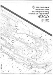
<strong>Simrad</strong> <strong>SP90</strong>1.2 System overviewMain unitsThe <strong>Simrad</strong> <strong>SP90</strong> sonar consists of the following units:• Wheelhouse units:- Display monitor- Sonar Operating Panel- Processor Unit- Loudspeaker• Sonar room units:- Transceiver Unit- Hull Unit→Seefigure1onpage3forthe<strong>SP90</strong>systemdiagram.Wheelhouse unitsThe Display Monitor is normally a 18” or 20” high-resolutioncolour LCD (Liquid Crystal Display). In addition to the sonarpicture, the monitor can also display the user menu for theinteractive operation. In order to ease the situation comprehension,certain colours have been chosen to better the distinction betweenthe various elements in the scene.The Operating Panel contains all necessary control functions foroperating the sonar. The controls are arranged in function groups,which gives a clear and easy operation. Note that all sonaroperation also may be made from the roller ball, or from anoptional remote standard mouse.The Processor Unit contains a ruggedized computer withinterface for the auxiliary equipment (log, gyro, GPS, echosounder, trawl systems, purse seine systems etc.). The processorunit runs the Microsoft Windows 2000® operating system,modified by <strong>Simrad</strong> to suit the <strong>SP90</strong> sonar requirements. Onesignal cable is used for the communication with the TransceiverUnit in the sonar room.The Loudspeaker reproduces the audio of the echoes for theselected audio channel.2 850-164511 / B
System descriptionDisplayunit115/230Vac mainsOperatingpanel115/230Vac mainsSpeed logCourse gyroGPSProcessorunitLoudspeakerEcho sounderTrawl systemPurse seine systemTransceiver UnitHull Unit115/230Vac mains(CD5997 / WMF / GIF)230/380/440Vac3 phase mainsFigure 1<strong>SP90</strong> System diagram850--164511 / B3
<strong>Simrad</strong> <strong>SP90</strong>WARNINGSonar room unitsThe Transceiver Unit is located in the sonar room, close to theHull Unit. One signal cable is used for communication with theProcessor Unit in the wheelhouse. The transceiver performs thesignal processing and the digital beamforming of the 256transmitters and 256 receiver channels, which are located on theeight identical transceiver boards.The standard Hull Unit is designed to be lowered 1.2 meters belowthe ship’s hull. (An optional hull unit will lower the transducer to1,6 meters below the hull.) The transducer can also be lowered toany selectable middle position. Note that in case of voltage failure,the Hull Unit can be manually raised or lowered by means of a handcrank.The cylindrical 256-elements transducer allows the sonar beamto give full 360 degrees coverage of the water volume down to -60degrees.The optional sensor for the electronic stabilization of the sonarbeams is housed in the motor control unit which is mounted on theHull Unit.If the transducer hits larger objects or bottom, the transducershaft may be bent, or in worst case it can be broken off. Abroken transducer shaft will cause water leakage in the top ofthe shaft. To prevent larger leakages in such a case, do not raisethe transducer shaft to the upper position. To prevent seriousdamages it is therefore of great importance to have a goodpump and warning system in the sonar room.4 850--164511 / B
System description1.3 OptionsGeneralThe standard <strong>SP90</strong> is a single 26 kHz version with maximum 60degrees tilt, and without beam stabilization.Note that the options described below are pre-programmed into thestandard version. A code word is required to make the actual optionavailable. <strong>Simrad</strong> offers a 1 month free test period for each option.→ To enter the code words, refer to the procedure on page 49.For a permanent installation of any of the option, a new code wordwill be released when ordering the option.Stabilization systemWhen the optional beam stabilizer is activated, both horizontal andvertical beams will be stabilized electronically for roll and pitchmovements up to ±20 degrees. The beam direction will thenchange continuously according to the vessel’s movements, andsecure an optimal contact with the targets even in rough seas.Figure 2Optional stabilization systemTriple- or multiple-frequencyIn addition to the standard 26 kHz frequency, options are availablefor triple and multiple frequencies.• In the triple-frequency version, you can select between 24 kHz,26 kHz and 28 kHz.• In the multiple-frequency version you can select from 11frequenciesfrom20to30kHzin1kHzsteps.These selections are particulary useful when it is necessary tosuppress interference from other sonars.850--164511 / B5
<strong>Simrad</strong> <strong>SP90</strong>Scientific outputThe Scientific Output is designed for research purposes. Whenactivated, the following data are available on an Ethernet (LAN)output:• Beam data• Target data• Own ship data• Gear dataThe scientific output option does not include any storage module.6 850--164511 / B
System description1.4 Functional descriptionIntroductionThe basic principles of the <strong>SP90</strong> sonar are unique because of the256 separate transmitter and receiver channels with theirtransducer elements spread around on the cylindrical transducerarray.The transmission, reception and data processing are undercomputer control, and the powerful capabilities of the sonar are theresults of sophisticated digital signal processing software and stateof the art hardware.Functional principlesWhen the Omni beam is tilted, the total beam picture can becompared with folding an umbrella, which means that all beamsin 360 degrees around the vessel have the same tilt angle.Figure 3Omni beamThe beam can be tilted from +10 up to -60 degrees down.In addition to seeing the target from above, it is also possible to seethe target from the side, by using the vertical slice presentation. Inthis case the beam covers a continuous vertical beam from 0 to -60degrees in one transmission.850-164511 / B7
<strong>Simrad</strong> <strong>SP90</strong>Figure 460 degrees vertical sliceThis vertical slice, which is presented by the white audio line in thehorizontal picture, can be selected to any bearing by the manualtraining control. The combination of the Omni mode and thevertical slice will give an optimal visualization of the catchsituation.Figure 560 degrees Omni/Vertical combination8 850-164511 / B
System descriptionIn addition to the Omni picture, the vertical slice is especiallyuseful for visualizing the vertical distribution of a school of fish.In that way, it is not necessary to go over the target to see thedistribution on the echo sounder, which often results in a spreadingof the school.When the optional stabilization system is installed in the sonar, thehorizontal and vertical beams will be stabilized electronically forroll and pitch up to approximately ±20 degrees. The stabilizationmay be switched on and off in the menu.ReceptionA great effort has been made to reduce unwanted noise to get aclean and stable echo presentation. To achieve this goal the sonarreceiver has the following filtering possibilities:FM Correlation filterIn addition to the traditional single frequency transmitting method,the <strong>SP90</strong> sonar is equipped with an FM correlation mode.In FM mode each transmission pulse contains up to eight differentfrequencies, and the receiver makes a spectrum analysis andcompares the received echoes with the transmitted frequency code.This provides a filtering effect, which efficiently reducesinterference, noise and reverberation. In addition to giving a cleanand stable echo presentation, this will normally also increases thesonar’s detection rangeFrequency selection (Option)The optional triple- and multiple frequency selections can be usedfor suppression of interference from other sonars.However, the sound absorption in salt water increases with thefrequency, thus giving the lower frequencies a longer detectionrange.→For more information about this option and the variousfrequencies available, refer to the description on page 5.AGC (Automatic Gain Control)This control will automatically adjust the gain in the preamplifiersdepending on the strength of the incoming echo signals. Thestrength of the filter can be selected in the menu.Note that the AGC senses the echo strength in five fixed directions,and use this as a basis for adjusting all the receiver beams.850-164511 / B9
<strong>Simrad</strong> <strong>SP90</strong>RCG (Reverberation Controlled Gain)The RCG filter senses the noise level (reverberation, propellernoise, etc.), and adjusts the gain individually for each of the 64receiver beams in order to eliminate noise on the display. Thestrength of the filter can be selected in the menu. With maximumstrenght is selected, the RCG will effectively reduce the bottom inshallow water, while variations on the bottom will be displayed.Note that scattered fish can be perceived as reverberation. TheRCG filter must therefore be used with care if scattered schools areto be detected.PP FilterThe <strong>SP90</strong> sonar is equipped with a ping-to-ping filter to give aclean and steady presentation by reducing the interference andnoise. This filter compares the echoes from a selected amount oftransmissions (pings), and an echo has to be present in the selectedamount of pings in order to be presented on the display.Note that in rough seas, when the beam easily can miss the targetin several pings, the PP filter must be used with care.TVG (Time Variable Gain)The TVG function controls the gain of the receiver so that a schoolwith a given size and density is presented with approximately thesame strength on the display, inside the regulated TVG range. Thiscan also be seen as a filter, because it reduces the noise close to thevessel.The regulated strength of the TVG can be selected in the menu.TransmissionThe transmitting is controlled by the signal processor in theTransceiver Unit. The parameters you have chosen are used.There are 256 separate transmitters in the unit distributed on eighttransceiver circuit boards. Each transmitter is individuallyaddressed and controlled from the signal processor. The controlledparameters include power output and time delay for eachtransducer element in order to form a beam with the selected tiltangle.10 850-164511 / B
System description1.5 Peripheral equipmentThe <strong>SP90</strong> sonar requires connection to a speed log and a coursegyro. An inaccurate log or gyro input will cause inaccurateindication of the vessel and target movements.In addition to log and gyro, the following peripheral equipment canbe connected to the sonar.• A (D)GPS may be connected to the <strong>SP90</strong> sonar to establish thevessels position and provide cursor and marker latitude andlongitude.• <strong>Simrad</strong> echo sounders (EQ, ES and EK Series) provides abottom plot on the catch data page.• <strong>Simrad</strong> PI32 Net Monitoring system provides the net depth indigits and bars on the catch data presentation.• <strong>Simrad</strong> trawl instrumentation; FS 900, FS 3300 or ITI- FS 900 and FS 3300: The trawl will be displayed in correctdepth.- ITI: The trawl will be displayed in correct size, depth,distance and bearing.• A radio buoy system (GPS type) will provide the geographicalposition of the buoy(s) in the sonar picture.For connection of any of this peripheral equipment, contact yourlocal dealer.850--164511 / B11
<strong>Simrad</strong> <strong>SP90</strong>2 DISPLAY MODES2.1 IntroductionThis chapter describes the <strong>SP90</strong> display modes. The various modesrepresent the graphical presentation of sonar data.Nine different display modes are generated to present the bestpossible presentation and flexible choices for a large range of userapplications.Display mode selection is made on the second menu button in themain menu. The four first display modes shown can also easily beselected with the four Mode buttons on the Sonar Operating Panel.Refer to the following pages for detailed descriptions of theoperational modes.→ Bow Up, page 13.→ North Up, page 14.→ True Motion, page 15.→ 180° / Audio, page 16.→ 270° / Vertical, page 17.→ Bow Up / Vertical, page 18.→ True Motion / Vertical, page 19.→ Dual 1, page 20.→ Dual 2, page 21.Note that the descriptive order of the display modes in this chapterhas been chosen only to simplify the descriptions. In operationalconditions, the order of the display modes depends on the selectedgear (seine net, bottom trawl or pelagic trawl) This is becausedifferent initial display modes are used for easy selection by thefour Mode buttons on the Sonar Operating Panel. The order ofthese display modes can easily be changed in the Sort Mode menu.→ The Sort Mode menu is explained on page 68.All the display modes in the following chapters are shown withoutechoes.12 850-164511 / B
Display modes2.2 Bow UpWhen Bow Up mode is selected, the vessel symbol is stationary onthe screen with the bow pointing upwards. The echo presentationcovers 360 degrees around the vessel, and all echoes are updatedfor every ping. The distance from the vessel symbol to the outerecho ring is equal to the selected range.The movement of the echoes across the screen are controlled by acombination of the vessel’s course and speed and the target’s ownmovements.In this example, the menu field is shown with the Horizontalmenu, which is used to control the sonar parameters.850--164511 / B13
<strong>Simrad</strong> <strong>SP90</strong>2.3 North UpWhen the North Up mode is selected, true north is always up onthe screen. The vessel symbol is stationary with the bow pointingin the vessle’s course direction.The movement of the echoes across the screen are controlled by acombination of the vessel’s course and speed and the target’s ownmovements.14 850-164511 / B
Display modes2.4 True MotionWhen the True Motion mode is selected, the picture is locked toa geographical position, where the vessel moves around the screenaccording to its present course and speed. All echoes are alwayspresented in their correct position relative to the vessel, and theirmovements on the screen will be a true representation of themovements of the targets through the water.When the vessel symbol reaches the edge of the screen, it willautomatically be moved back to the centre, or to a positiondetermined by the Off Centre button. This position is reset to thescreen centre whenever the mode is changed.When you select Target Track, the target will automatically bemoved to the screen centre.850-164511 / B15
<strong>Simrad</strong> <strong>SP90</strong>2.5 180° /AudioWhen the 180° / Audio mode is selected, the upper half of thescreen shows a 180 degrees bow-up presentation, while the lowerpart is used for a recording of the audio channel.The audio channel is shown with a continuous white line in thehorizontal picture, and it can be trained in any direction. Therecorded echoes are a direct replica of the echoes under the whiteaudio line.As the audio channel is recorded over a period of time, this modeis especially useful for detection of weak echoes mixed withreverberation or noise.The information recorded by the audio channel is always stored inthe computer, even if another mode is selected. That means thatthis recording will always be presented when selecting the180°/Audio mode.Note that the vessel symbol can be moved to any position in thehorizontal view with the cursor and Off Centre button.16 850-164511 / B
Display modes2.6 270° /VerticalThe 270° / Vertical mode is specially designed for purse seining.The vertical half slice is displayed in the lower left corner fornormal setting with the net on the starboard side. If the net is seton the port side, the 60 degrees vertical slice will be displayed inthe lower right hand corner.With this presentation, it is easy to keep the best contact with aschool in both the vertical and horizontal presentation, and todetermine its size distribution. The position of the school relativeto the bottom is another important information provided by thispresentation.The Catch data presentation for purse seining is shown on theright hand side. It shows all the net data relative to the target andthe bottom, as well as all available target data.850-164511 / B17
<strong>Simrad</strong> <strong>SP90</strong>2.7 Bow Up / VerticalWhen the Bow Up / Vertical mode is selected, the picture isdivided into three sections; where the left side is a bow-uppresentation similar to the bow-up presentation previouslydescribed.The upper part on the right hand side is a catch data presentation,while the lower part is a 60 degree vertical slice presentation.18 850-164511 / B
Display modes2.8 True Motion / VerticalWhen the True Motion / Vertical mode is selected, the picture isdivided into three sections; where the left side is a true motionpresentation similar to the true motion presentation previouslydescribed.The upper part on the right-hand side is a catch data presentation,while the lower part is a 60 degrees vertical slice presentation.850-164511 / B19
<strong>Simrad</strong> <strong>SP90</strong>2.9 Dual 1The Dual mode is a kind of “two sonars in one” operation, whereeach presentation is updated for every second transmission. Allsettings can be set individually for each of the two presentations.This makes the dual mode especially useful for optimizing settingsby directly comparing the two presentations.To optimize the horizontal settings, use the Horizontal menu to trydifferent settings in the upper picture. These settings areautomatically transferred to the other modes.The dual operation may also be used for other user applications,where different range, tilt, frequency and other parameters can beselected.20 850--164511 / B
Display modes2.10 Dual 2The Dual 2 mode is very similar to the Dual 1 mode previouslydescribed, but the “two sonars” are presented next to each other..All settings can still be set individually for each of the twopresentations.850-164511 / B21
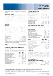
<strong>Simrad</strong> <strong>SP90</strong>3 SONAR OPERATING PANEL3.1 IntroductionYou may enter operational commands directly on the SonarOperating Panel. Sonar functions may also be accessed andactivated using the menu field on the display and the trackball onthe operating panel.Frequently used functions are directly accessed by the designatedcontrol buttons. These are grouped according to their purpose.SIMRADMAIN SW.SYMBOLMODEGAINRANGECURSORPOWERMode1GainH -GainH +RangeH -RangeH +Menu Select View ObjectUpMode2MiddleMode3GainV -GainV +RangeV -RangeV +DownMode4TILTVARIOUSTRAINManualZoomPositionTrackManualAutoRecordOffCentreTargetTrackAutoSearchSONAR OPERATING PANELFigure 6 Sonar Operating Panel(CD5377B)A thorough understanding of system functions and controls isnecessary to optimize overall performance. Sonar conditions vary,sometimes drastically, and it is not possible to identify settings thatwill provide the best data at all times. Careful study of theinformation in this manual is highly recommended, preferablywhile exploring the sonar’s various functions. System operation isa dynamic activity requiring regular adjustments and fine tuningto achieve the best possible results under varying environmentalconditions.3.2 The fieldsThe operating panel fields are described on the following pages.22 850-164511 / B
Sonar Operating PanelMain switchMain switch functions control power to the sonar, hoisting andlowering of the transducer and indicates the transducer’s currentposition.MAIN SW.UpMiddleDown(CD5346)PowerPressing Power for approximately two seconds powers up thesonar. The adjacent green LED blinks while the Sonar Control Unitboots up, and remains illuminated once the system is operational.Before the sonar can be powered down, the transducer must be inthe Up position. Pressing the Power button for approximately twoseconds secures power to the unit which is confirmed by theadjacent green LED being extinguished.UpRaises the transducer to its upper position. The adjacent green LEDblinks while the transducer is raised and remains illuminated onceit is housed safely inside the hull of the vessel. The green blinkingLED will also be accompanied by an audible signal.MiddleRaises or lowers the transducer to its middle position.The physical location of the middle position can be defined in themenu.→ Refer to the Transducer parameter description on page 137.DownLowers the transducer to its lower position. The adjacent greenLED blinks while the transducer is lowered and remainsilluminated when lower position is reached. The green blinkingLED will also be accompanied by an audible signal.850-164511 / B23
<strong>Simrad</strong> <strong>SP90</strong>SymbolThe Symbol functions provide on-screen graphic references fortargets, own ship and fishing gear.(CD5347)SYMBOLTargetmarkerOwn shipmarkerCirclemarkerGearsymbolTarget markerTo mark a target, move the cursor over it and press thebutton. A triangular symbol with a correspondingnumber will appear on the screen over the target.Position data for the definedmarkers are displayed inthe Objects menu.Notre that the system continues to track the markerseven when outside the sonar range.The Target marker function can also be used formanual target tracking as the system is designed tocalculate the speed (S), course (C) and distance (D)between the last two chosen targets.The Target marker data is displayed in white figuresfor three minutes in the lower right hand corner of thehorizontal presentation. This function is also aneffective method for determining the distance betweentwo selected points on the screen.Own ship markerThe “own ship” button produces a square symbol on the screen atthe vessel’s current location when the button is pressed. The ownship marker’s position data is displayed in the Objects menu.Circle markerThis marker may be used to estimate the size of a school of fish oras an indication of the size of the purse seine. To activate thefunction, move the cursor to the desired position and press thebutton. A circular symbol will appear on the screen at the chosenlocation. The size of the symbol is equal to that of the purse seineselected.Gear symbolThe gear symbol may be either a purse seine circle or a trawlsymbol depending on the parameter chosen by the Gear button inthe Setup menu. The selected gear symbol will be displayed inyellow.Seine circleThis is a useful aid in planning the shooting of the purse seine. Itis used as follows:24 850-164511 / B
Sonar Operating Panel1 Press the Gear button.- The purse seine circle will appear on the forward end ofthe ship symbol on the corresponding side of the vesselselected in the Setup menu. The circle will follow thevessel’s movements.2 At the moment the seine is shot, press the Gear button again.- The purse seine circle will remain stationary and indicatethe ideal path for setting the seine. Four square symbolson the ship’s course line indicate the: shooting, onequarter, one half, three quarters and end of the seinepositions. Three different nets can be pre-programmed inthe Gear menu.3 Press the Gear buttontodeletethePurse Seine circle.Trawl symbolThis is a useful aid in providing an overview of the trawl operation.Trawl data can be set manually using the menu or automatically byinterfacing the <strong>Simrad</strong> FS trawl sonar or ITI trawl monitoringsystem with the sonar.• In the manual mode the trawl symbol will be displayed on theship’s course line with the selected size, depth and distance.• When the FS 900 or 3000 trawl sonar is connected, the trawlsymbol will automatically be displayed with the correct depthin the vertical modes.• When the ITI trawl system is connected, the trawl symbol willbe displayed with the correct distance, bearing and depth. Ifrequired, the trawl opening, ambient water temperature, andtrawl-filling indicator may also be displayed.850-164511 / B25
<strong>Simrad</strong> <strong>SP90</strong>ModeMODEMode1Mode2Mode3Mode selection can be performed using the menu or the maincontrol panel which contains four operator selectable Modebuttons.Frequently used modes that are task-specific to particular phasesof the fishing operation can be pre-set in the Sort Modes menu.→ The Sort Modes menu is described on page 68.For example Mode 1 may be used for the search phase, Mode 2 forthe evaluation phase, Mode 3 for the catch phase and Mode 4 forthe Dual operation.→ The display modes are described from page 12.Mode4(CD5348)26 850-164511 / B
Sonar Operating PanelGainGain controls are specified as either horizontal or vertical.GAINGain Gain_H H +Gain Gain_VV +Horizontal gainThe two upper buttons control receiver gain effectingthe horizontal presentation of the sonar. The level ofgain selected is display in the Horizontal menu and ontop of the tilt indicator in the upper left-hand side of thedisplay. It has 51 selectable values numbered from 0 to50 and may be changed in steps of 1 dB.Vertical gainThe two lower buttons control receiver gain effectingthe vertical presentation of the sonar. The level of gainselected is display in the Vertical menu. It has 51selectable values numbered from 0 to 50 and may bechanged in steps of 1 dB.(CD5351)850-164511 / B27
<strong>Simrad</strong> <strong>SP90</strong>RangeRange controls are specified as either horizontal or vertical.RANGERange Range_H H +Horizontal rangeThe two upper buttons control the horizontal range.The range selected is displayed in the Horizontalmenu, and on top of the tilt indicator in the upper leftcorner of the display._RangeVRangeV +Vertical rangeThe two lower buttons control the vertical range. Therange selected is displayed in the Vertical menu.(CD5352)28 850-164511 / B
Sonar Operating PanelCursorThe cursor is used for on screen cursor orientation and menuoperation.CURSORMenu Select View ObjectSONAR OPERATING PANEL(CD5771)MenuThe Menu button is used forselection between Menu or FullScreen presentations. When themain menu is displayed, the echopresentation will be reducedcorrespondingly. In full screenpresentation, the full dimension ofthe screen is used for the echopresentation.When the full screen echopresentation is displayed, the cursormay be used to activate the menufield by moving it to the left or rightextremes of the screen. Moving thecursor outside the menu field willhide the menu.→ Menu and full screen presentations are explained on page 38.SelectThe Select button is used to execute a selection. This correspondsto the left button on a standard mouse.ViewThe View button activates the View pop-up menu for the selecteddisplay window. This button corresponds to the middle button ona standard mouse.→ The View pop-up menu is described on page 69.ObjectThe Object button activates the Object pop-up menu for theselected display window. This button corresponds to the rightbutton on a standard mouse.→ The Object pop-up menu is described on page 71.850-164511 / B29
<strong>Simrad</strong> <strong>SP90</strong>TrackballThe trackball controls the cursor. The cursor changes appearancein relation to its location on the screen:• An Orange cursor in the echo field.• An arrow in the menu field.• A negative or positive sign at each end of the menu buttons.- The negative or positive sign indicates the direction in whichthe corresponding parameter values will be changed whenthe Select button is pressed.→ A detailed description of the menu buttons is provided on page 42.30 850-164511 / B
Sonar Operating PanelTrainThe audio channel is displayed as a continuous white line. It canbe trained either manually or automatically. The bearing angle isdisplayed in the upper right-hand corner of the display, indicatedrelative to the bow.(CD5354)ManualAutoSearchTRAINManualIn the Manual modethe train left (arrow)or train right (arrow)buttons are used todirect the audio lineto the desiredbearing.Auto searchIn the Auto Search mode the sonar will automatically searchwithin pre-set sector limits with the selected audio line designatingthe centre of the search. The search sector is displayed on thebearing card with two white angular symbols.• The search sector is adjusted by pressing and holding the AutoSearch button and simultaneously pressing the train left(arrow) or train right (arrow) buttons .• The Automatic Search function is overridden when either thetrain left (arrow) or train right (arrow) buttons are pressed andwill continue once released. The present bearing at the momenteither button is released will become the centre of the search.Position trackThe Position Track function is only available when both a coursegyro and a speed log are interfaced with the sonar system.To track a fixed position, place the cursor over the desired locationand press the Position Track button. A geographically fixed circlewill appear on the display and its position automatically tracked bythe system.When the Auto Tilt function is activated in the Position Trackmode the tilt angle’s centre is automatically adjusted with regardto the distance to the tracked position.850-164511 / B31
<strong>Simrad</strong> <strong>SP90</strong>NoteTarget trackTo track a target, place the cursor over the desired location andpress the Target Track button. A circle will appear on the displayand its position automatically tracked by the system using thestrongest echo centred in the ”window” represented by two lineson the audio line. The “window’s” size may be selected by theTrack Window buttonintheSetup menu.The vector originating from the target’s centre indicates its courseand speed. The length of the vector increases relative to the target’sspeed. One knot is represented by a small mark on the vector. Acourse line can also be displayed showing the target’s track.Target tracking symbols and data are displayed with a light violetcolour. In addition to the information on the Catch data page, thespeed, course and distance for some modes are found in the lowerleft hand corner of the screen.When the Auto Tilt function is activated in the Target Trackmode, the tilt angle will automatically follow the strongest echo.The upper and lower tilt angle limits can be used to preventtracking surface or bottom echoes.Manual training overrides the Target Tracking function.32 850-164511 / B
Sonar Operating PanelTiltManual tiltIn Manual mode the transducer may be tilted within the systemslimits by pressing the Tilt up (arrow) or Tilt down (arrow) buttons.Pressing either button once changes the tilt angle in steps of 1degree. Pressing and holding either button continuously changesthe tilt angle until finger pressure is removed.(CD5349)NoteTILTAuto tiltIn the Auto Tilt mode the selected tilt angle forms theManualcentre of the tilt search. The selected tilt limits aredisplayed on the tilt indicator by yellow lines andcorresponding numerical values for both the upper andlower limits.AutoThe centre of the tilt search sector is adjusted bypressing the Tilt up (arrow) or Tilt down (arrow)buttons. Sector limits are adjusted by pressing andholding the Auto button and simultaneously pressingthe Tilt up (arrow) or Tilt down (arrow) buttons.Tilt search sector limits can be incremented in steps of 1 degree to10 degrees according to the value selected in the in the Tilt menu.The Auto Tilt function responds differently with regard to thetraining mode selected as follows:• Manual training mode: The transducer automatically changesthe tilt angle after each transmission in steps within the selectedlimits.• Auto search training mode: The transducer automaticallychanges the tilt angle after each complete search is performed.• Position tracking mode: The tilt angle’s centre willautomatically be adjusted with regard to the distance to theposition being tracked. The transducer will tilt automatically insteps after each transmission.• Target tracking mode: The tilt angle will automatically beadjusted to provide the strongest echo within the selectedtracking sector. The upper and lower tilt limits can be used toprevent tracking surface or bottom echoes.If the optional stabilization system is installed and activated, thebeamformer will automatically adjust the tilt angle with regardto the vessel’s motion (even if manual tilt is selected). The changein the tilt angle for the beamformer will not be shown on the tiltindicator.850-164511 / B33
<strong>Simrad</strong> <strong>SP90</strong>VariousThe buttons grouped under various are Zoom, Record, Mute andOff Centre.Record(CD5353)VARIOUSOffCentreMuteThe Mute button is used as to activate and deactivatethe echo audio channel and to acknowledge audiblealarms.The Mute function is also available on the Displaymenu.RecordThe record function is used for storing either asequence or single display picture. Sequential or singlestorage options are preset in the Store/Recall menu(available from the Setup menu).→ The Store/Recall menu is described on page 66.If sequential store mode is selected, Record is used for starting andstopping the storage. If single shot storage is selected a new pictureis storage each time the button is pressed.ZoomThe zoom function magnifies an area of the display by positioningthe cursor in its centre and pressing the Zoom button. The Zoombutton works as a toggle switch for on/off of the zoom function.Off centreThe Off Centre function moves the Own vessel symbol to thecursor’s position on the display. This adjusts the presentation to fillthe screen accordingly.34 850-164511 / B
Operation4 OPERATION4.1 IntroductionNoteWhat this chapter containsAll operation of the sonar is normally made from the SonarOperating Panel. Optionally, a standard mouse or trackball maybe connected, and the sonar can then be operated by means of themenu system alone.This section contains a detailed description of the start and stopprocedures, the principles of the menu operation, and otheroperational procedures for the daily use of the <strong>SP90</strong>.In order to obtain the necessary understanding of the sonar design,refer to the System description chapter. The various presentationformats are described in the Display modes chapter.→ The System description is provided from page 1.→ The Display modes are explained from page 12.The following procedures are provided in this chapter:→ Start and stop procedure, page 36.→ Menu operation, page 38.→ Visual aids, page 45.→ Cosmetics, page 46.→ Installation of options, page 49.→ On-line help, page 51.Remember that the standard <strong>SP90</strong> transducer in its lower positionreaches 1,2 meters below the vessel’s hull (1,6 meters for optionalversion). Maximum recommended speed in that position is 20knots!Maintaining the sonarTo ensure the best possible reliability of the <strong>SP90</strong> sonar, it isimportant to follow the maintenance procedures described in theMaintenance chapter.→ Refer to page 147.CautionNoteImportant when docking the vesselWhen docking the vessel, the switch S102 at the rear of the SonarProcessor Unit must be switched to the OFF position to preventinadvertent use of the sonar. The transducer can be damaged ifallowed to transmit in air.→ For location of the switch S102, refer to figure 8 on page 37.When docking, refer to the Maintenance chapter.850--164511 / B35
<strong>Simrad</strong> <strong>SP90</strong>4.2 Start and stop proceduresNoteBefore you start the sonar, check that the water depth is sufficient,and that the vessel’s speed is within the maximum speed specifiedwith the transducer lowered.Start procedureObserve the following procedure to power up the sonar.MAIN SW.UpMiddleDown1 Press the Power button on the monitor to power up thedisplay monitor.2 Press and hold the red Power button on the Sonar OperatingPanel for approximately two seconds to start the sonar.- The green LED next to the button indicates that the sonarstarts loading the program. After approximately one anda half minutes the sonar picture will be displayed.3 Press the Down button to move the transducer to the lowerposition.- The green LED next to the button will flash, and anaudible signal indicates that the transducer movesdownwards.- When the bottom position has been reached, the LED willilluminate continuously, the audible signal stops, and thetop button in the Status parameter dialogue shows:Transducer: DOWN.This completes the normal start-up procedure.In case of power failure, or if the switch S102 at the rear side of theSonar Processor Unit has been switched off, the sonar must bestarted by pressing the start switch S103. This switch is locatedbehind the small front door on the Sonar Processor Unit.Stop procedure1 Press the Up button on the Sonar Operating Panel to hoist thetransducer to the upper position.- The green LED next to the button will flash, and anaudible signal indicates that the transducer is hoisted..When the upper position has been reached, the LED willilluminate continuously, the audible signal stops, and theupper button in the Status menu shows: Transducer: UP.2 Press and hold the Power button approximately two secondsto switch off the sonar.36 850--164511 / B
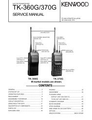
OperationS103PWRHDAPC 10(CD5881 / GIF)Figure 7 S103 on the front of the Processor Unit3 Check that the green LED next to the On/off buttonextinguishes.4 Press the Power button on the display monitor to switch itoff.WARNINGIf the sonar is switched off uncontrolled withthe transducer lowered, the transducer mustbe raised by means of the hoist/lower switch inthe Motor Control Unit, or with the hand crank.Procedures for emergency hoisting are provided in theMaintenance chapter.→Refer to page 152 for manual hoisting and lowering.Dry-docking safety measuresTo prevent inadvertent use of the sonar when dry-docking etc., setthe switch S102 at the rear of the Sonar Processor Unit to the Offposition.NoteThe transducer can be damaged if transmitting in air.SIMRADS102(CD5880 / GIF)Figure 8 S102 on the rear side of the Processor Unit850--164511 / B37
<strong>Simrad</strong> <strong>SP90</strong>4.3 Menu operationIntroductionThe menu system on the <strong>SP90</strong> sonar is designed to allow for easyand fast access to the parameters.The menu can be removed from the screen.Some of the parameters (for example Range, Gain and Tilt) canbe controlled both from the button on the menu and from buttonson the Sonar Operating Panel. The parameter values shown on themenu buttons will then change according to the setting made on thepanel.It is also possible to operate the sonar with a standard computermouse.38 850--164511 / B
OperationScreen presentationsThe menu can be set up for permanent display, or available onlywhen required for parameter alterations. The Menu button on theSonar Operating Panel is used to select Menu or Full Screenpresentation.Figure 9 Typical screen presentation withthe menu on the right hand sideIn Menu presentation, the menu is always shown on the right handside of the display, and the size of the echo area will be reduced.When Full Screen is selected, the echo presentation is extended tocover the entire display.→ A standard menu presentation is shown in figure 9.→ A full screen presentation with the menu disabled is shown infigure 10.Once the menu has been disabled, observe the following procedureto recall it for temporary use.1 Use the trackball, and move the cursor to the outmost leftorright hand side on the display.2 Observe the menu appear on top of the echo area, and that theremaining echo area is not re-scaled.3 Move the cursor outside the menu, and observe that itdisappears.→ The position of the temporary menu is shown in figure 11.850--164511 / B39
<strong>Simrad</strong> <strong>SP90</strong>Figure 10Full screen presentation without menuFigure 11Full screen presentation with menu40 850--164511 / B
OperationMenu structureThe menu field on the sonar display contains several differentbuttons, tabs and parameter dialogues.Sonar typeModeselectionTab for menuselectionActive menuParameterselectionStatus(defaultdialogue)• Sonar type: The upper “button” indicatesthe sonar in operation. You can not pressthis button.• Mode selection: The second button isused to display the current mode. You canpress this button to select a different mode.• Menu: The next field contains the mainmenu. Depending on operational modeand the menu properties, this menu cancontain a number of buttons or otherinformation.• Parameter dialogue: When a menubutton is pushed, the applicable dialoguewith a selection of parameters appears atthe bottom of the menu.• Tab: These selections on the right handside of the menu allows you to choosebetween the menus applicable for thecurrent operational mode. The menu fieldwill provide different tabs for each displaymode. In order to select a new menu, movethe cursor to the tab, and press Select.All the tabs, menus and submenus will beexplained in chapter Menus.→ The menus are described from page 52.(CD6407B)850--164511 / B41
<strong>Simrad</strong> <strong>SP90</strong>Menu buttonsEach menu contains several buttons. Each button shows both thefunction and the current parameter. The majority of the buttons ineach menu field have three functions.• You can select a lower parameter value.• You can select a higher parameter value.• You can open the applicable dialogue.(CD5899/BM578)+-(1) (3) (2)Figure 12 Menu button1 Decrease: Position the cursor on the left side the button.Observe the arrow symbol change to a minus sign: Decreasethe parameter by pressing the Select button.2 Increase: Position the cursor on the right side the button.Observe the arrow symbol change to a plus sign: Increasethe parameter by pressing the Select button.3 Dialogue: Position the cursor on the centre of the menubutton. Observe the arrow symbol change to a menusymbol. Open the parameter dialogue by pressing the Selectbutton.. The dialogue appears in the lower part of the menufield, providing an overview of the available options.42 850--164511 / B
OperationCURSORMenu Select View ObjectSONAR OPERATING PANELSelecting a new parameter valueThe menu system is operated by the trackball and the Select buttonon the Sonar Operating Panel.However, when you have gained moreexperience, and have become more familiar withthe available options, you will select theparameters directly from the “smart” buttons.When the parameter dialogue has been opened,the parameters can be changed in two differentways.First method:1 Use the increase/decrease function on thebutton to move the parameter pointer up ordown in the dialogue.2 Close the dialogue by pressing the centre of the button.Second method:1 Move the cursor down to the parameter dialogue.2 Move the cursor up and down on the parameter list.3 Press Select when you have found the requested parameter.4 Press Close to close the dialogue.(CD5768B)Press the button on the menu.Observe the parameter dialogue appear.Make the necessary changes.Press Close to finish.The parameter value shown in the button is operational evenwithout closing the parameter dialogue. This makes it easy to testthe effect of each parameter setting. Note that the transceiverrelated parameters will first be in operation in the next ping.850-164511 / B43
<strong>Simrad</strong> <strong>SP90</strong>Stored parametersDefault settingsThe parameter settings identified with an asterisk (*), indicates thenormal setting known to perform well under normal conditions. Ifyou get “lost“ in the parameter settings, the Default settingsfunction will bring up these normal parameters.The Default setting function is available on the Setup menu, anda dedicated parameter dialogue is used.→ The Default setting dialogue is described on page 93.User settingsThe User setting function allows you to store chosen parametersettings for various types of fisheries, or your favourite individualsettings. The saved settings can easily be retrieved into theoperational sonar.The User setting function is available on the Setup menu, and adedicated parameter dialogue is used.→ The User setting dialogue is described on page 142.Parameter memoryThe <strong>SP90</strong> sonar is equipped with a battery powered memory. Thisfunction will cause the sonar to remember all the selectedparameter settings, even when the sonar is switched off.44 850--164511 / B
Operation4.4 Visual aidsCommon information on the displayIn nearly all display modes, the following information is provided.• The Tilt indicator is displayed in the upper left corner. Theselected range and gain is shown on top of this indicator.• The orange text in the upper right hand corner of the echo areashows the bearing, distance and depth of the cursor. If a GPS isconnected to the sonar, the geographical latitude and longitudefor the cursor location will also be displayed.Range Gain Geographical position Bearing (B)Tilt indicator(CD6341)Distance and depthFigure 13Common information on the displayMoving the boundary linesIn most display modes with multiple views, the size of each viewcan easily be modified by moving the boundary line between theviews.Locate the cursor on the boundary line, press and hold Select andmove the cursor with the Select button depressed. When the buttonis released, the boundary line will be located at the new cursorposition.850-164511 / B45
<strong>Simrad</strong> <strong>SP90</strong>4.5 CosmeticsThe choices in the Cosmetics menu allows you to enable or disablea range of visual aids in the sonar picture.→ The Cosmetics menu is described on page 65.Figure 14 Sonar display with Wind Marker,Distance Rings and Bearing Card enabledThe Bearing Card shows the current bearing relative to the vessel.The markers are shown as short white lines for every 10th degreealong the outer circle of the sonar view.The Distance Rings are shown as dotted rings, each with a rangereadout on the left hand side of the display centre.The Wind Marker is shown as an arrow drawn from the Compasscard pointing towards the centre of the display. If a wind sensoris connected to the sonar, it will automatically show the currentwind direction. Otherwise, the wind direction may be enteredmanually. The arrow has a fixed length, it is not scaled accordingto the current wind speed.→ The Wind direction parameter is explained on page 143.46 850-164511 / B
OperationFigure 15 Sonar display with Variable rangemarker, Compass card and Vertical ring enabled.The VRM (Variable Range Marker) consists of an adjustable rangering with range readout. It can be used for any type of distancemarking relative to the vessel. To adjust the marker, locate thecursor on the marker ring, press Select and move the cursor withthe Select button depressed. When the button is released, thevariable range marker radius will be moved to the new cursorposition.The Compass Card is shown as short yellow lines for every 10thdegree along the outermost circle of the sonar view. A trianglesymbol indicates each 45th degree. It has labels indicating North,East, South and West. It is updated when the heading of own shiphas changed more than 1 degree, if the display mode is Bow up.The Vertical Ring shows the selected range of the vertical slice asa full circle in the horizontal presentation. This is an indication ofwhich distance a target should be presented in the vertical view.The Vertical Ring will only be visible in those modes that supporta vertical slice. In other modes, the button will give no response.850-164511 / B47
<strong>Simrad</strong> <strong>SP90</strong>Figure 16 Sonar display with vertical Depthdividers, Track history with Minute markers, Bowmarker, Bearing card markers and Wind markerenabled.The Depth dividers are horizontal dotted lines used to visualizethe depth steps in the vertical slices.The Bow Marker is heading marker. It is a dotted line drawn fromthe bow of your own ship in the same direction as the vessel’scurrent heading.The Minute markers are shown as small circles on the trackhistory of the ship.→ The Track history parameter is described on page 135.48 850-164511 / B
Operation4.6 Installation of optionsThe following options can be installed on the <strong>SP90</strong> sonar:• Triple- or multiple-frequency• Stabilization→ For more information, see “Options” on page 5.Note that all options are pre-programmed into the standard sonarversion, and that <strong>Simrad</strong> offer a 1 month free test period for eachoption. When ordering a permanent option installation, a codeword will be released from <strong>Simrad</strong>.For a free test, or permanent option installation, use the followingprocedure:1 Select the Setup menu.2 Press the Test button to activate the System test menu.3 Press the Installation Menu button.4 Observe that the installation menu bar is shown on the top ofthe screen.5 Press Options on the menu bar.6 Select Install Options to activate the Install optionsparameter dialogue.The following parameters are available in the Install optionsdialogue.850-164511 / B49
<strong>Simrad</strong> <strong>SP90</strong>NoteHWID - This field displays the unique 12-character HardwareIdentification code. This code is different for each <strong>SP90</strong> sonar.<strong>Simrad</strong> uses this code to generate the 32-characters code word usedfor a permanent option installation.Try - A number of buttons, where each will start the 1 month freetest period for the chosen option.If any time or date adjustments are made during the test period, theoption will be closed.Add License String - This button is used for permanentinstallation of the chosen option. When you press the button, thiswill activate the On-Screen Keyboard used to type the required32-character code word.Procedure:1 Press Add License string.2 Place the cursor in the text field.3 Type the code word.4 Check that the 32 characters is entered correctly into the textfield5 Press the Apply License String button.6 Restart the sonar.7 Check if the actual option is opened and operable.50 850-164511 / B
Operation4.7 On-line helpThe <strong>SP90</strong> sonar is equipped with a comprehensive on-line helpsystem. It is available from all the parameter dialogues and menusby pressing the Help button.Help is provided in two levels: On-line and Free.Once pressed, the first Help text will appear in the bottom of themenu. This is the On-line text. It is short, context sensitive, anddesigned not to interrupt the operation of the sonar. To close theHelp dialogue, press the Close button.To access more detailed information, press the Free button. Thiswill open the complete interactive manual. It contains the sameinformation as the printed Operator manual, but the informationis accessed using the menu on the left hand side and interactivelinks throughout the document.Press Free in the bottom left corner to return to the small On-linedialogue, or Close to exit the interactive manual.Note that if you press Close, the large interactive manual willautomatically reappear the next time you press a Help button.850--164511 / B51
<strong>Simrad</strong> <strong>SP90</strong>5 MENU DESCRIPTIONS5.1 IntroductionThis section provides a detailed description of the complete menusystem for the <strong>SP90</strong> sonar, and contains the chapters listed below.For an explanation of how to operate the menu system, refer to thesection Menu operation.The <strong>SP90</strong> comprises a large number of different menus on severallevels. Menus are selected by pressing their respective tabs on theright side, and the appearance of menus and tabs depends on thechosen operation mode and the current settings. The menu typescan be organised as follows:• Active menus are those relevant for each of the display modes.The active menus are available at all times selectable theappropriate tab.→ The Active menus are listed on page 57.• Temporary menus are the “sub-menus” activated by a buttonin one of the Active menus. (Examples are Cosmetics, Test,etc.)→ The Temporary menus are listed on page 64.• View pop-up menus are those activated by using the Viewbutton on the Sonar Operating Panel, or the middle mousebutton (provided a mouse is installed).→ The View pop-up menus are listed on page 69.• Object pop-up menus are those activated when you use theObject button on the Sonar Operating Panel, or the right mousebutton (provided a mouse is installed).→ The Object menus are listed on page 71.• View menus are those menus activated in the View pop-upmenus described above.→ The View menus are described on page 73.• Messages are those menus used to handle various messagesfrom the system to the user.→ The Messages are described on page 77.The chapter Menu structure gives a description of the menu systemconfiguration with references to more detailed descriptions of allthe menu.→ The Menu structure is described in more detail on page 54.52 850--164511 / B
Menu descriptionAny selections you do in the menus will bring up the parametersavailable for the chosen setting. The Alphabetical list ofparameters is a useful aid to find a description of a particularparameter of all available parameters incorporated in the <strong>SP90</strong>sonar system.→ The alphabetical list of parameters is provided on page 83.850--164511 / B53
<strong>Simrad</strong> <strong>SP90</strong>5.2 Menu structurePurposeThis chapter gives a description of the sonar’s menu configuration.Sonar typeMode selectionTab for menuselectionActive menuParameter selectionStatus(default dialogue)(CD6407B)54 850--164511 / B
Menu descriptionSonar typeThe upper menu field is only a sonar type indicator. The menuidentifies the name of the sonar.Mode selectionThe top menu button displays the current operational mode, andallows you select an other.The standard <strong>SP90</strong> sonar has nine different operational modes.All the various display modes are described in section Displaymodes.→ The Display modes are listed on page 12.To open the Mode parameter, move the cursor to the Mode buttonin the menu, and press the Select button on the Sonar OperatingPanel.The four upper modes in the menu may be selected directly withthe four Mode buttons on the operating panel. Note that these fourmodes may be changed to any of the available modes.To change the order of the display modes, use the Sort Modesmenu.→ The Sort Modes menu is described on page 68.850--164511 / B55
<strong>Simrad</strong> <strong>SP90</strong>MenusThe sonar contains a number of menus.The menus are shown with vertical tabs on the right hand side, andyou can easily select a menu by using the trackball and the Selectbutton on the Sonar Operating Panel. These menus provide thestatus for the current settings, and give access to perform changesin these settings.The menus are sorted in categories.→ The menu categories are listed on page 52.StatusThe Status dialogue is the default view displayed in the lower,right hand corner of the screen.The Status dialogue can not be closed, but if an other parameter isselected it will be overwritten. The dialogue contains a transducerposition indicator, as well as readouts of current time, date,latitude, longitude, heading and speed.The following parameters are available:→ Transducer, page 137.→ Time and Date, page 134.→ Heading, page 104.→ Speed, page 127.The position information are simply presentations of the currentinformation available.56 850--164511 / B
Menu description5.3 Active menusOverviewThe Active menus are those relevant for the different operationalmodes. The menus are shown with vertical selector tabs on theright hand side, and each menu can easily be selected using thetrackball and the Select button on the Sonar Operating Panel.All menus have access to on-line help through a Help button.The following Active menus are described in this chapter:→ Horizontal, page 58.→ Vertical, page 59.→ Display, page 60.→ Setup, page 61.→ Objects, page 62.→ Second Ping, page 63.850-164511 / B57
<strong>Simrad</strong> <strong>SP90</strong>HorizontalThe Horizontal menu is used for the horizontal sonarpresentations. These are present in all display modes. When ahorizontal parameter setting is selected and defined in one mode,the chosen settings will automatically be applied to all modes.The following parameters are available:→ Range, page 117.→ Tilt, page 132.→ Bearing, page 87.→ Gain, page 102.→ Pulse Form, page 115.→ Tx Power, page 139.→ Ping Sector, page 113.→ Frequency, page 101.→ TVG (Time Variable Gain), page 138.→ AGC (Automatic Gain Control), page 85.→ RCG (Reverberation Controlled Gain), page 120.→ PP Filter, page 114.→ Audio volume, page 86.The Help button opens the on-line help.→ The on-line help is described on 51.58 850-164511 / B
Menu descriptionVerticalThe Vertical menu is only shown in modes with a vertical slicefunction. All relevant settings, except the TX Power, can beselected separately for the vertical modes independent of thehorizontal settings. When any vertical setting is selected anddefined in one mode, the setting will be applied to all verticalmodes.The following parameters are available:→ Range, page 117.→ Bearing (Vertical), page 89.→ Gain, page 102.→ Pulse Form, page 115.→ Tx Power, page 139.→ Frequency, page 101.→ TVG (Time Variable Gain), page 138.→ AGC (Automatic Gain Control), page 85.→ RCG (Reverberation Controlled Gain), page 120.→ PP Filter, page 114.→ Audio volume, page 86.The Help button opens the on-line help.850-164511 / B59
<strong>Simrad</strong> <strong>SP90</strong>DisplayThe Display menu is shown in all display modes, and providesaccess to parameters controlling the visual presentation of thesonar views. Some of the choices on the menu are simple on/offbuttons.Full Screen - Replica of the Menu button on the Sonar OperatingPanel.Audio Mute - Replica of the Mute button on the Sonar OperatingPanel.Resolution - Select 16 or 64 colours in the display presentation.The chosen resolution is shown in the colour bar below the button.Bearing - Set the audio bearing to Relative Ship or True North.The following additional parameters are available:→ Palette, page 111.→ Display Gain, page 95.→ Colour Threshold, page 90.→ Colours, page 91.→ Panel backlight, page 112.→ Language, page 106.→ Units, page 140.→ Cosmetics, page 65.→ Menu, page 107.The Help button opens the on-line help.60 850-164511 / B
Menu descriptionSecond pingThe Second ping menu is only shown when you operate in any ofthe Dual modes. It allows you to define the parameters for the“second sonar” independently of the other. The parametersavailablearethesameasintheHorizontal menu.→ The Dual display mode is explained on page 19.The following parameters are available:→ Range, page 117.→ Tilt, page 132.→ Bearing, page 87.→ Gain, page 102.→ Pulse Form, page 115.→ Tx Power, page 139.→ Ping Sector, page 113.→ Frequency, page 101.→ TVG (Time Variable Gain), page 138.→ AGC (Automatic Gain Control), page 85.→ RCG (Reverberation Controlled Gain), page 120.→ PP Filter, page 114.→ Audio volume, page 86.The Help button opens the on-line help.850-164511 / B63
<strong>Simrad</strong> <strong>SP90</strong>5.4 Temporary menusThe Temporary menus are those selected from the active menus.They are also shown with vertical tabs on the right side of themenu, and can easily be selected by the trackball and the Selectbutton. The Temporary menus must however be removedmanually using the Close button in the bottom of menu.All Temporary menus have access to on-line help through a Helpbutton.The following Temporary menus are described in this chapter:→ Cosmetics, page 65.→ Store/Recall, page 66.→ Test, page 67.→ Sort Modes, page 68.64 850-164511 / B
Menu descriptionSystem testThe System test menu is activated by the Test button in the Setupmenu.The System test menu provides several test routines available toperform operational and functional tests. These tests are designedonly to be carried out by qualified service engineers.The following parameters are available:Test Configuration - This function is only to be activated byqualified service engineers.Toggle TxPower - This function is only to be activated byqualified service engineers.Test Beam - This function is only to be activated by qualifiedservice engineers.Roll - This is not a button, it is a readout from the sensor of theactual roll value at the time of the last transmission.Pitch - This is not a button, it is a readout from the sensor of theactual pitch value at the time of the last transmission.Interpolation - This is a built-in software function that may givea more realistic presentation of the echos.Message bar - This button opens the Message bar parameterdialogue, which allows you to monitor operational messages fromthe sonar.→ Message bar, page 108.Installation menu - This button opens the Installation menu onthe top of the display. This menu is used during installtion of thesonar, and information about this is provided in the Installationmanual.About - This button provides access to a small informationdialogue providing the current software version.→ About, page 84.The Close button closes this menu.The Help button opens the on-line help.850-164511 / B67
<strong>Simrad</strong> <strong>SP90</strong>Sort ModesThe Sort Modes menu is activated by the Sort Modes button inthe Setup menu.The Sort Modes menu is used to select the display modes to beactivated by the four Mode buttons on the Sonar Operating Panel.The four upper display modes in this menu will always be the fourmodes selectable by the four Mode buttons in the order they aresorted.In order to sort the modes, select the actual mode and use the MoveUp and Move Down buttons to place it in the wanted position.When the modes are organized in the requested order, press theApply button to store the information.68 850-164511 / B
Menu descriptionView pop-upThe View pop-up menu is accessed using the View button over thetrackball on the Sonar Operating Panel, or the middle mousebutton if an optional mouse is installed.When activating the pop-up menu in the Catch Data view, it willdisplay the following reduced menu.The View pop-up menu contains the following parameters.Set New Display CentreWhen Set New Display Centre is selected, the new display centreis moved to the cursor’s position where the View menu wasactivated.Ship To CenterWhen Ship To Centre is selected, the own ship symbol is movedto the centre of the view.ZoomThe zoom function magnifies an area of the display by positioningthe cursor in its centre and pressing the Zoom button. The zoombutton works as a toggle switch for on/off of the zoom function.Erase EchoesWhen Erase Echoes is selected, all echoes displayed on the sonarview will be deleted.SynchronizeThis function is not operational on the <strong>SP90</strong> sonar. Forsynchronization to external equipment, refer to the Setup menu.850-164511 / B69
<strong>Simrad</strong> <strong>SP90</strong>Make Same SizeWhen Make Same Size is selected, window areas tiled verticallywill acquire the same width.Grey scale dataThis command changes the display from a colour presentation toa black-and-white. The number of shades of grey and the numberof different colours used will be the same.The Grey scale data command can be selected for singular sonarviews independent of each other.View menuWhen View Menu is selected menus will be displayed accordingto the view in which the cursor is situated. Several different Viewmenus are available.→ Refer to chapter View menus, on page 73.70 850-164511 / B
Menu descriptionObject pop-upAccess and purposeThe Object pop-up menu is accessed using the Object button overthe trackball on the Sonar Operating Panel, or the right mousebutton if an optional mouse is installed.This pop-up menu is mainly used when you operate the sonar froman optional mouse, as most of the functions on it can be selecteddirectly on the Sonar Operating Panel.Note that the cursor related selections in the Object pop-up menuuse the cursor position where the pop-up menu was activated.Normal choicesThe following functions are provided by the the Object pop-upmenu when you click in a random location on the display.• These choices provide the same functions as their respectivebuttons on the Sonar Operating Panel:- Target Track- Position Track- Set Marker- New Own Ship Marker- Circle Marker- Gear Symbol• These choices are specific, and can only be activated from theObject pop-up menu- New rulerNew RulerWhen New Ruler is selected, a straight line is drawn from thecurrent cursor position (where the Object pop-up menu wasselected) to another selectable position. The ruler will displayrange and bearing between the two points.850-164511 / B71
<strong>Simrad</strong> <strong>SP90</strong>To remove the ruler, click on it with the right mouse button, andselect Remove ruler from the Object pop-up menu.Inspect RulerIf you click on an existing ruler, the Ruler dialogue will appearunder the menu. This dialogue will povide information about theselected ruler, and it allows you to remove the ruler with a Deletebutton.→ The Ruler dialogue is described on page 122.Extended choicesActivating the Object pop-up menu whilst positioning the cursorover a defined object on the display, it will display the followingadditional parameters.• Inspect • Delete • Make priority targetInspect When Inspect is selected, the object parameters aredisplayed at the bottom of the menu in the Inspect Objectparameter dialogue.→ The Inspect Object dialogue is described on page 105.Delete When Delete is selected, the object will be removed.This is the same function as provided by the Objects menu.Make Priority TargetThis function can be used to give priority to an “old” target trackingsymbol, which locks the audio channel on the target.72 850-164511 / B
Menu description5.5 View menusThe View menus are activated from the View pop-up menu, whichagain is accessed using the View button on the Sonar OperatingPanel or the middle mouse button.The View menus are shown with vertical tabs on the right handside, and the menus can easily be closed using the Close button inthe lower part of each menu.All menus have access to on-line help through a Help button.The following View menus are described in this chapter.→ GeoView, page 74.→ VertView, page 75.→ CatchView, page 76.850-164511 / B73
<strong>Simrad</strong> <strong>SP90</strong>GeoViewThe GeoView menu is activated by pressing the View button on theSonar Operating Panel or the middle mouse button in anyhorizontal view, and then selecting View menu in the Viewpop-up.The GeoView menu provides control of selected parametersrelated to the current data displayed in the horizontal view; Scaleand Target track. It also provides you with a button to repositionthe vessel symbol.The following parameters are available:Ship to centre - Moves the ship symbol to the centre of the view.→ Scale, page 123.→ Target Track, page 131.The Close button closes this menu.The Help button opens the on-line help.74 850-164511 / B
Menu descriptionVerticalViewThe VerticalView menu is activated by pressing the View buttonon the Sonar Operating Panel or the middle mouse button whilepositioning the cursor in any of the vertical views, and thenselecting View menu in the View pop-up.The VerticalView menu provides control of selected parametersrelated to the current data displayed in the vertical view; Zoom,Zoom scale and Data source.The following parameters are available:→ Zoom, page 145.→ Zoom Scale, page 146.→ Data Source, page 92.When Indicator is selected in the Data Source dialogue thefollowing additional option is available.→ Direction Indicator, 94.The Close button closes this menu.The Help button opens the on-line help.850-164511 / B75
<strong>Simrad</strong> <strong>SP90</strong>CatchViewThe CatchView menu is activated by pressing the View button onThe Sonar Operating Panel or the middle mouse button while thecursor is located in the Catch wiew, and then selecting View menuin the View pop-up.The Catch view is only available in the 270/Vertical, TrueMotion/Vertical and Bow up/Vertical display modes, and youmay need to hide the menu to see it.The CatchView menu provides control of selected parametersrelated to the current data displayed in the Catch view.The following parameter is available:→ Range, page 119.The Close button closes this menu.The Help button opens the on-line help.76 850-164511 / B
Menu description5.6 MessagesMessage categoriesWhen necessary, the sonar will provide you (or your serviceengineer) with operational and technical messages. Thesemessages are sorted into four categories.• Warnings• Operator alarms• System alarms• ErrorsIn order to access the messages, the Message Bar must be enabled.This function can be set to activate itself when necessary.→ The Message Bar is described on page 108.The Message Bar is located at the bottom of the display, and itcontains four buttons, one for each category of messages. Thesebuttons give an overview of the number of unread messagescurrently in the system. Each of the four buttons gives access to adialogue where each message can be read, acknowledged anddeleted.→ Warnings, page 78.→ Operator alarms, page 79.→ System alarms, page 80.→ Errors, page 81.When no messages are present, the four buttons are grey. Whenone or more unread messages exists, the Warning andOperational Alarm buttons are yellow, while the System Alarmand Error buttons are red.850-164511 / B77
<strong>Simrad</strong> <strong>SP90</strong>WarningsThe Warnings menu is activated from the Warnings button in theMessage Bar.The Warnings menu displays the warning messages issued by thesonar. Each warning is identified with time of issue and a heading.Additional information is found in the small text field below themessage list.The top of the message list with the most recent messages is alwaysdisplayed when the dialogue is opened. Acknowledged messagesare displayed in grey.Use the cursor and select individual messages with the Selectbutton on the Sonar Operating Panel.Ack(knowledge) - Press this button to acknowledge the selectedmessage.Delete - Press this button to delete the selected message.The Close button closes the menu.The Help button opens the on-line help.78 850-164511 / B
Menu descriptionOperator alarmsThe Operator alarms dialogue is activated from the Op.AlarmsbuttonintheMessage Bar.The Operator alarms menu displays the alarms issued by thesonar. Each alarm message is identified with time of issue and aheading. Additional information is found in the small text fieldbelow the message list.The top of the message list with the most recent messages is alwaysdisplayed when the menu is opened. Acknowledged messages aredisplayed in grey.Use the cursor and select individual messages with the Selectbutton on the Sonar Operating Panel.Ack(knowledge) - Press this button to acknowledge the selectedmessage.Delete - Press this button to delete the selected message.The Close button closes the dialogue.The Help button opens the on-line help.850-164511 / B79
<strong>Simrad</strong> <strong>SP90</strong>System alarmsThe System alarms dialogue is activated from the Sys.AlarmsbuttonintheMessage Bar.The System alarms dialogue displays the alarms issued by thesonar. Each alarm message is identified with time of issue and aheading. Additional information is found in the small text fieldbelow the message list.The top of the message list with the most recent messages is alwaysdisplayed when the dialogue is opened. Acknowledged messagesare displayed in grey.Use the cursor and select individual messages with the Selectbutton on the Sonar Operating Panel.Ack(knowledge) - Press this button to acknowledge the selectedmessage.Delete - Press this button to delete the selected message.The Close button closes the dialogue.The Help button opens the on-line help.80 850-164511 / B
Menu descriptionErrorsThe Errors dialogue is activated from the Errors button in theMessage Bar.The Errors menu displays the alarms issued by the sonar. Eacherror message is identified with time of issue and a heading.Additional information is found in the small text field below themessage list.The top of the message list with the most recent messages is alwaysdisplayed when the menu is opened. Acknowledged messages aredisplayed in grey.Use the cursor and select individual messages with the Selectbutton on the Sonar Operating Panel.Ack(knowledge) - Press this button to acknowledge the selectedmessage.Delete - Press this button to delete the selected message.The Close button closes the dialogue.The Help button opens the on-line help.850-164511 / B81
<strong>Simrad</strong> <strong>SP90</strong>6 PARAMETERS6.1 About parameter dialogues and helpThis chapter describes all the parameter dialogues accessed fromthe menu system.When a parameter is selected, the available choices are shown inthe dialogue below the menu. The setting is then made using theavailable buttons or lists. Several levels are frequently used toselect the parameters.Note that:1 In many cases you will not need to open the parameterdialogue, as you can control the settings directly on the menubutton.2 The parameter is selected and activated by the sonar once itis highlighted in the dialogue. The operational changes canthus be investigated from within the dialogue withoutclosing it.3 The Close button will always close the dialogue.4 The Help button will always provide short-form contextsensitive help. This help text will appear on top of theparameter dialogue, and you need to press Close to return.In the Help window, you can also press Free to access to fullinteractive manual. This may not be available in all modes,as it will block the view of the sonar echoes.Once the interactive manual has been accessed, you need topress Free to reduce the large help window back toshort-form presentation. If you press Close in the interactivemanual, the manual will automatically appear next time youpress Help in a parameter dialogue.The menu settings marked with an asterisk, indicate the normalsetting which perform well under normal conditions. If one got lostin the menu settings, a Default Settings function will bring upthese normal settings.After experience, when the contents of the menus are betterknown, the increase/decrease function on the actual menu buttoncan be used directly without selecting the submenu.82 850-164511 / B
Parameters6.2 Alphabetical listThe following is an overview of available parameters incorporated in the <strong>SP90</strong> sonarsystem.→ About, page 84.→ AGC, page 85.→ Audio volume, page 86.→ Bearing, page 87.→ Bearing (Vertical), page 89.→ Colour Threshold, page 90.→ Colours, page 91.→ Data Source, page 92.→ Date and time, page 134.→ Default setting, page 93.→ Direction Indicator, page 94.→ Display Gain, page 95.→ Edit gear (Purse), page 96.→ Edit gear (Trawl), page 97.→ Edit school, page 98.→ External synchronisation, page 99.→ Fish alarm, page 100.→ Frequency, page 101.→ Gain, page 102.→ Gear, page 103.→ Heading, page 104.→ Inspect object, page 105.→ Language, page 106.→ Menu, page 107.→ Message Bar, page 108.→ Mode, page 109.→ Movements, page 110.→ Palette, page 111.→ Panel backlight, page 112.→ Ping Sector, page 113.→ PP Filter, page 114.→ Pulse Form, page 115.→ Range, page 117.→ Range (CatchView), page 119.→ RCG, page 120.→ Recall, page 121.→ Recall Mode, page 121.→ Ruler, page 122.→ Scale, page 123.→ School data, page 124.→ Scientific output, page 125.→ Slant Range, page 126.→ Speed, page 127.→ Stabilizer, page 128.→ Status, page 129.→ Store, page 130.→ Store Mode, page 130.→ Target Track, page 131.→ Tilt, page 132.→ Time and date, page 134.→ Track History, page 135.→ Track Window, page 136.→ Transducer, page 137.→ True range, page 126.→ TVG, page 138.→ Tx Power, page 139.→ Units, page 140.→ User Setting, page 142.→ Wind Direction, page 143.→ Wind Speed, page 144.→ Zoom, page 145.→ Zoom Scale, page 146.850-164511 / B83
<strong>Simrad</strong> <strong>SP90</strong>AboutThe About parameter dialogue is accessed from the System testmenu.The About dialogue is only used to provide information about thecurrent software version. In addition, the Versions button opens asmall text document with detailed version information. Thisinformation is not intended for operational use.84 850-164511 / B
ParametersAGC (Automatic Gain Control)The AGC parameter can be accessed from the Horizontal,Vertical and Second ping menus.The AGC (Automatic Gain Control) adjusts the gain in the sonar’spreamplifier circuitry. This gain depends on the strength of theincoming echo signal. The result is a filter effect, reducing noiseand reverberation. As show in the menu, the AGC has fourdifferent settings.Off - no gain adjustmentWeak - slow gain adjustmentMedium - medium fast gain adjustmentStrong - fast gain adjustmentNote that the AGC is sensing the echo strength in five directions,and use this as a basis for common adjustment for all the receiverbeams.850-164511 / B85
<strong>Simrad</strong> <strong>SP90</strong>Audio volumeThe Audio volume is accessed from the Horizontal and Verticalmenus.The Audio Volume in the loudspeaker can be selected in 10 steps.The audio channel, from which the audible information isretrieved, is shown with a continuos white line. This line can betrained by the training controls on the Sonar Operating Panel orfrom the Train button in the menus.The audio signal can easily be muted by the Mute button on theSonar Operating Panel, or by the Mute button the Display menu.Both these buttons work as a toggle switch, which means that thesecond press on the switch will recall the audio signal.86 850-164511 / B
ParametersBearing (Horizontal)The Bearing parameters are accessed from the Horizontal andSecond ping menus.The Bearing of the audio channel is normally controlled from theSonar Operating Panel. The selected bearing is shown with acontinuous white line pointing out from the transducer position.This line can be trained manually or automatically in any position.The angle readout on the bearing button can be selected to be ±180degrees relative to the bow, or absolute (relative north).More information about the Auto Search program are provided inthe Sonar Operating Panel description.→ Refer to page 31.The following options are available:Left arrow - Train left.Right arrow - Train right.Search Step - This button opens a new dialogue to select the searchstep angle. This angle defines how many degrees the search beamshall move for each transmission in the Auto Search mode.Search Sector - This button opens a new dialogue to select theactive audio search sector. This sector can be adjusted between 22and 360 degrees directly with the increase/decrease buttonfunction, or by the - or + buttons in the Search Sector dialogue.The search sector limits will be shown on the outer part of the echocircle with two white angular symbols.Absolute (true) - Sets bearing relative to true north.Relative - Sets bearing relative to the bow of the vessel.Manual - In this mode, the audio channel may be trainedcontinuously in either direction by pressing the “train left“ or “trainright” buttons.850-164511 / B87
<strong>Simrad</strong> <strong>SP90</strong>Auto -IntheAuto Search mode, the sonar will automaticallysearch within the selected Search Sector.88 850-164511 / B
ParametersBearing (Vertical)The Bearing (Vertical) parameter is accessed from the Verticalmenu.This dialogue allows you to train the audio channel bearingmanually.The Bearing of the audio channel is normally controlled with theTrain buttons on the Sonar Operating Panel. The bearing of thevertical slice, which is presented by the white audio line in thehorizontal picture, may also be trained by the Bearing button in theHorizontal menu.The following options are available:- (minus button) - Train left.+ (plus button) - Train right.More information about the Train buttons are provided in theSonar Operating Panel chapter.→ Refer to page 31.850-164511 / B89
<strong>Simrad</strong> <strong>SP90</strong>Colour ThresholdThe Colour Threshold button is located in the Display menu.The Colour Threshold function is used to reduce the number ofecho colours on the display.The strength of the echoes is indicated with a scale of 16 or 64colours. A weak echo has a cold colour (blue), medium echoeshave warmer colours (green, yellow) and strong echoes are shownwith the warmest colours (orange, red). If desired, the number ofcolours may be reduced. When you do this, the sonar witll startwith the colour indicating the weakest echoes. Therefore, byreducing colours, the maximum detection range will be reduced,because all echoes will normally appear as weak echoes at longranges.90 850-164511 / B
ParametersColoursThe Colours button is located in the Display menu.The colour strength of the echo presentation can be selected withthree different colour scales. Under normal conditions, theNormal colours will give the best dynamic in the echopresentation.Do not confuse this parameter with the Colour Threshold setting.→ The Colour Threshold parameter is described on page 90.850-164511 / B91
<strong>Simrad</strong> <strong>SP90</strong>Data SourceThe Data Source button is located in the Vertical View menu.The View menus are activated by pressing the View button on theSonar Operating Panel or the middle mouse button, whilepositioning the cursor in any of the vertical views, and thenselecting View menu on the View pop-up menu.The Data Source parameter is used to select the bearing source ofthe vertical views.Audio - The vertical slice will follow the trainable audio channel.Indicator - The bearing of the vertical slice can be adjustedindependent of the Audio channel.In addition, the vertical slice may be selected to three fixedsettings: Forward, Aft, orAthwart.92 850-164511 / B
ParametersDefault SettingDefault Setting is accessed from the Setup menu.This function makes it possible to delete all the parameterscurrently saved in the sonar’s memory, and re-install those definedby <strong>Simrad</strong> instead; the factory default settings. These defaultsettings are identified with an asterisk in the different parameterdialogues and menus, and will perform well under normalconditions.850-164511 / B93
<strong>Simrad</strong> <strong>SP90</strong>Direction IndicatorThe Direction Indicator is accessed from the Vertical View menuwhen Data Source is set to Indicator.→ The Data Source parameters are explained on page 92.The Vertical View menu is activated by pressing the View buttonon the Sonar Operating Panel (or the middle mouse button) whilepositioning the cursor in any of the vertical views, and thenselecting View menu on the View pop-up menu.The Trawl Menu is accessed in the same manner, but with thecursor located in the Trawl view.Here the vertical slices can be trained independent of the audiochannel.The direction indicator is shown in the horizontal presentation asa yellow dotted line.94 850-164511 / B
ParametersDisplay GainDisplay Gain is accessed on the Display menu.The Display Gain increases or decreases the presentation of theecho colours on the display.In order to adjust the receiver gain, refer to the individual Gainparameters accessed in the Horizontal and Vertical menus.850-164511 / B95
<strong>Simrad</strong> <strong>SP90</strong>Edit Gear (Purse)The Gear parameter dialogue is accessed on the Setup menu. Eachof the available options in the Gear dialogue can be edited usingthe Edit button. When a purse has has been selected, this parameterdialogue is provided.→ The Gear parameter dialogue is explained on page 103.These parameters allows you to define the depth and the length ofyour purse seine, as well as which side of the vessel it is positioned.The following options are available.Depth - This function allows you to enter the depth of your purseseine. When the Gear symbol is selected, the depth of the purseseine will be shown on all vertical views.→ The Gear symbol is described on page 24.Length - This function allows you to enter the length of your purseseine. When the Gear symbol is selected, the seine circle will beshown in correct size.Throw Side - This function is used to position the seine circle onthe port or starboard side of the vessel.Separate parameter dialogues are used to make the selections.96 850-164511 / B
ParametersEdit Gear (Trawl)The Gear parameter dialogue is accessed on the Setup menu. Eachof the available options in the Gear dialogue can be edited usingthe Edit button. When a trawl has has been selected, this parameterdialogue is provided.→ The Gear parameter dialogue is explained on page 103.These parameters allows you to monitor or define the distance anddepth of your trawl, as well as the height and width of your trawlopening. If you use the <strong>Simrad</strong> ITI system, these parameters willbe provided automatically.The following options are available:Distance - Set the distance to the trawl manually, or automaticallyif the ITI Trawl system is connected.Depth - Set the depth of the trawl manually, or automatically if theITI Trawl system is connected.Height -Set the height of the trawl opening, or automatically if theITI Trawl system is connected.Width - Set the width of the trawl opening manually, orautomatically if the ITI Trawl system is connected.Length - Set the length of the trawl symbol.Each parameter is defined in a separate dialogue.850-164511 / B97
<strong>Simrad</strong> <strong>SP90</strong>Edit schoolThe Edit School parameter dialogue is accessed from the SchoolbuttonintheSetup menu. In the School dialogue, select speciesand press Edit.The top button displays the fish species selected in the Schooldialogue.→ The School parameter dialogue is described on page 124.The Edit School dialogue displays the species of fish and itspresently selected density. The density for the school volumeestimation is based on kg/m@ school area. The default value is 25kg/m@ for all species, and you may adjust this figure individuallyin the Density parameter dialogue accessed by the Density button.98 850-164511 / B
ParametersExternal SynchronizingThe External Synchronizing button is located in the Setup menu.The External synchronization function makes it possible toeliminate interference from other <strong>Simrad</strong> sonars on board thevessel. If the sonars are connected together, you can use thesesettings to synchronise their transmissions.Two options are available.Sync mode - Select None, Slave or Master.• None disconnects the <strong>SP90</strong> from the synchronisation system,.The sonar will then operate completely on its own.• Slave connects the <strong>SP90</strong> as a slave to an external system. Theexternal system will then instruct the <strong>SP90</strong> to when it cantransmit.• Master allows the <strong>SP90</strong> to be in control- The sonar will theninstruct the external system on when it can transmit.Delay - Select the delay between the <strong>SP90</strong> transmission and thetransmission of the external system, or vice versa.Separate parameter dialogues are used to make the choices.850-164511 / B99
<strong>Simrad</strong> <strong>SP90</strong>Fish alarmThe Fish Alarm button is located in the Setup menu.The Fish Alarm function makes it possible to set up the sonar towarn you when a school of fish are detected inside the selectedsector. The selected sector is displayed with white dashed lines inthe horizontal picture.• Fish Alarm - On/Off switch used to activate or deactivate thefish alarm.• Start Range - used to select the range for the alarm sector tostart. The start range can be selected between 0 and 7900 meters.• End Range - used to select the range for the alarm sector to end.The end range can be selected between 100 and 8000 meters.• Width - used to select the width of the alarm sector. The sectorwidth can be selected between 10 and 360 degrees.• Alarm Threshold - used to select at which echo level the alarmshould be activated. The selected echo level is shown with thewhite pointer in the echo colour bar below the AlarmThreshold button.The Close button closes this menu.The Help button opens the on-line help.100 850--164511 / B
ParametersFrequencyThe Frequency parameters can be called from the Horizontal,Vertical and Second ping menus.Note that this parameter dialogue is optional, it will only beavailable if the triple or multiple frequency option has beeninstalled on the sonar.The Frequency parameter dialogue is used to select the transmitterand receiver frequency. In addition to the standard frequency, anoptional multiple frequency version is available.If multiple frequencies are installed, they are mainly intended forsuppression of interference from other hydroacoustic equipment.However, the sound absorption in salt water decreases with thefrequency, thus giving lower frequencies a longer range.If only the standard frequency is installed, <strong>Simrad</strong> offers aone-month free test period for the multiple frequencies.850-164511 / B101
<strong>Simrad</strong> <strong>SP90</strong>GainThe Gain is accessed from the following menus: Horizontal,Vertical and Second Ping.The Gain is normally selected from the Sonar Operating Panel. Ithas 51 values, these are numbered from 0 to 50. The receiver gainis changed 1 dB per step. In addition to the readout on the Gainbutton, the horizontal gain is normally repeated over the tiltindicator in the upper left hand corner on the display.The default value is 30 dB.102 850-164511 / B
ParametersGearThe Gear button is located in the Setup menu.The Gear parameter dialogue is used to select the type of fishinggear, and to get the right size and position of the gear on the display.By using Edit... it is possible to program the system for threedifferent purse seines, three different bottom trawls, and threedifferent pelagic trawls.Refer to the following information:→ Edit gear (Purse), page 96→ Edit gear (Trawl), page 97850-164511 / B103
<strong>Simrad</strong> <strong>SP90</strong>HeadingThe Heading parameter is accessed by pressing the Hdg(Heading) button in the Status dialogue at the bottom of themenus.The Heading readout is a repetition of the connected course gyroinput. Manual heading input may be used if signals from externalsensors are missing. By selecting Manual,the+ and - buttons canbe used to alter the heading value.Important: This readout must not be used for navigation.104 850-164511 / B
ParametersInspect objectThe Inspect object parameters are either accessed when you selecta target marker in the Objects menu, or when you place the cursoron the marker and pushes the Select button on the Sonar OperatingPanel.The Inspect object parameter dialogue displays the currentparameters for the chosen object. Note that every parameter maynot be applicable for all marker categories.The following parameters are shown:-Depth- Distance- Bearing- Speed- Course- Geographical position-Area- VolumeThe Delete and Set Priority buttons allow you to remove anobject, or to change its status to “priority”.Delete - This button allows you to delete the chosen targetSet priority - This button sets the current target marker to the“priority” marker. The marker is then identified with a “P”.850-164511 / B105
<strong>Simrad</strong> <strong>SP90</strong>LanguageThe Language button is located on the Display menu.The Language parameter dialogue is used to select the languageon the menus.106 850--164511 / B
ParametersMenuThe Menu button is located in the Display menu.The Menu parameter is used to select different levels ofcomplexity of the menu system.• For simplified use, select the Short menu system. Only the mostimportant parameters will then be shown in the menus.• For normal operation, select Normal. This setting isrecommended for most users after some experince with thesonar.• For advanced use, select Full. All parameters in the menus willbe shown.850-164511 / B107
<strong>Simrad</strong> <strong>SP90</strong>Message BarThe Message Bar button is located in the System test menu. Thismenu is accessed by pressing the Test... button on the Setup menu.The sonar automatically issues messages when a disturbanceoccur. The messages are grouped into four categories; Errors,System alarms, Operational alarms and Warnings. TheMessage Bar parameter dialogue is used to select at which levelwarnings and alarms shall be presented.The Message Bar is located at the bottom of the display, and itcontains four buttons, one for each category of messages. Thesebuttons give an overview of the number of unread messagescurrently in the system. Each of the four buttons gives access to amenu where each message can be read, acknowledged and deleted.→ Warnings, page 78.→ Operator alarms, page 79.→ System alarms, page 80.→ Errors, page 81.When no messages are present, the four buttons are grey. Whenone or more unread messages exists, the Warning andOperational Alarm buttons are yellow, while the System Alarmand Error buttons are red.108 850-164511 / B
ParametersModeThe Mode button is located on the top of every menu.The Mode parameter dialogue is used to select display mode. Itwill automatically provide a selection between the modes currentlyavailable on the sonar.The various dipslay modes are described in the Display Modeschapter.→ Refer to page 12.The modes can also be selected with the four Mode buttons on theSonar Operating Panel. The various modes to activate using thosefour buttons are controlled by the Sort Modes menu.→ The Sort Modes menu is described on page 68.→ The Mode buttons on the Sonar Operating Panel are described onpage 26.850-164511 / B109
<strong>Simrad</strong> <strong>SP90</strong>MovementsThe Movements button is located in the Setup menu.The Movements function makes it possible to estimate theposition of a tracked school at a given time (from one to tenminutes). Estimate school position is presented by a violet dot.When selecting 0, the movement estimation is switched Off.110 850-164511 / B
ParametersPaletteThe Palette button is located in the Display menu.The Palette parameter dialogue is used to select backgroundcolours and day/night brightness of the display.850-164511 / B111
<strong>Simrad</strong> <strong>SP90</strong>Panel BacklightThe Panel backlight button is located in the Display menu.The Panel Backlight controls the illumination on the keyboard onthe Sonar Operating Panel in 8 steps (0 – 7).Note that the Panel Backlight can only be manually operated. TheAuto button is added for future expansion.112 850-164511 / B
ParametersPing SectorThe Ping Sector is accessed from the Horizontal menu.The Ping Sector is defined as the sector covered by one ping. Thesize of the sector can be selected between 360 degrees (Omni) and11 degrees (single beam). When you select 11 degrees, the currentbearing will be the centre of the audio beam.The audio beam can be turned manually by means of the Trainbuttons on the Sonar Operating Panel, or automatically in the AutoSearch or tracking programs.The Train buttons and the Auto Search program are described inthe Sonar Operating Panel chapter.→ Refer to page 31.850-164511 / B113
<strong>Simrad</strong> <strong>SP90</strong>PP FilterThe PP Filter can be accessed from the the following menus:Horizontal, Vertical and Second Ping.The PP Filter (Ping-to Ping filter) reduces unwanted noise andechoes from the screen.The filter has three different strengths. As the ping-to-ping filtercompares the echoes from the last 2 (Weak), 4 (Medium) or8(Strong) pings, it will take this selected amounts of pings to makea stable presentation when changing most of the sonar functions.The filtering routine takes the vessel’s movements intoconsideration when comparing the echoes from ping to ping.114 850-164511 / B
ParametersPulse FormThe Pulse Form is accessed from the following menus:Horizontal, Vertical and Second Ping.The Pulse Form parameter dialogue is used to select the form ofthe transmitter pulse. This could either be CW (Continuous Wave)with different pulse lengths, or FM (Frequency Modulation) withdifferent pulse lengths and number of frequencies.Range CW - Pulse length (ms) FM(meters) Short Normal Long Auto150 0.9 1.8 5.3 FM4300 1.8 3.5 10 FM4450 2.7 5.3 15 FM4600 3.5 7.1 20 FM4900 5.3 10 30 FM41200 6.2 12 35 FM81500 7.1 15 45 FM82000 10 20 60 FM82500 12 25 75 FM83500 18 35 75 FM84500 22 45 75 FM86000 30 60 75 FM88000 30 60 75 FM8CW (Continuous Wave)The frequency of the transmitter pulse is here constant, equal to theselected frequency (if the optional multiple frequencies areinstalled).850-164511 / B115
<strong>Simrad</strong> <strong>SP90</strong>There is a selection between three different pulse lengths: Short,Normal and Long. In addition the pulse length will changeautomatically in accordance with the selected range. The tableshows the different pulse lengths given in milliseconds (ms).FM (Frequency Modulation)In the FM mode, the transmitter pulse is frequency modulated.This provides a stable echo presentation and greater ability ofdetection as noise and reverberation are reduced.There is a selection between these different FM modes:• FM AUTO - This selection will automatically choose theoptimal number of frequencies for the selected range.- Ranges from 150 up to and including 900 meters will useFM4 (four frequencies).- Ranges from 1200 up to and including 8000 meters will useFM8 (eight frequencies).- In order to prevent different presentations caused bydifferent numbers of frequencies while changing rangebetween 900 and 1200 meters, the FM AUTO modeincludes a built-in memory function where Gain, Frequency,TVG, AGC, RCG, and PP-filter can be selected differentlyfor the FM4 and FM8 ranges. These selections will bememorized, and when you change between the 900 and 1200meters ranges, the system will reactivate the parameterselection you made the previous time the system wasoperating in that range interval.• FM1 - Transmits one-frequency pulse with a total pulse lengthof 1 ms.• FM2 - Transmits two-frequency pulses with a total pulse lengthof 4 ms.• FM4 -Transmits four-frequency pulses with a total pulse lengthof 16 ms.• FM8 - Transmits eight-frequency pulses with a total pulselength of 64 ms in ranges from 1200 and above, andfour-frequency pulses (FM4, 16 ms) from 900 meter and below.The selected number of frequencies are transmitted in one ping,and the receiver undertakes a spectrum analysis to compare thereceived echoes with the transmitter’s frequency code. Thisprovides a filtering effect, where only “own echoes” are displayed,and noise and other echoes are reduced. The table on the previouspage shows the maximum FM mode for all ranges.116 850-164511 / B
ParametersRangeThe Range parameter can be accessed from the button in theHorizontal, Vertical and Second ping menus.Horizontal and vertical range is normally selected using the <strong>SP90</strong>Sonar Operating Panel. You can also control these settings directlyon the Range button. The available choices are listed in thisdialogue.The Range buttons are described in the Sonar Operating Panelchapter.→ Refer to page 28.Available ranges (in meters): 150, 300, 450, 600, 900, 1200, 1500,2000, 2500, 3500, 4500, 6000 and 8000.In addition to the readout on the menu, the current horizontal rangeis normally displayed over the tilt indicator in the upper, left-handcorner of the display.The following options are available in the Range parameterdialogue:Manual - Allows you to change the range manually.Auto - Enables automatic range selection during position- andtarget tracking.To create an optimal position- or target tracking programme,automatic ranging may be selected by pressing the Auto (Tilt) orAuto Search buttons on the Sonar Operating Panel. To maintaina steady display during seine setting, the lower automatic range isset to 450 meters. Changing the range or pressing the Manualbuttons will stop the automatic ranging function.850-164511 / B117
<strong>Simrad</strong> <strong>SP90</strong>The <strong>SP90</strong> sonar is designed to work with various horizontal rangeunits such as meter, nautical mile, kilometres, US survey foot oryards. This choice can be made by pressing the Units button in theDisplay menu.→The Units parameters are described on page 140, while theDisplay menu is described on page 60.118 850-164511 / B
ParametersRange (CatchView)The Range (CatchView) button is located in the CatchViewmenu.The CatchView menu is activated by pressing the View button onThe Sonar Operating Panel, or the middle mouse button, while thecursor is located in the Catch view, and then selecting View menuon the View pop-up menu.The Range in the CatchView may be selected manually orautomatically.In Manual, the range scale can be selected between 200 meters and1000 meters as indicated in the dialogue.In Auto,theCatchView range will automatically follow the rangeselected in the Vertical view.850-164511 / B119
<strong>Simrad</strong> <strong>SP90</strong>RCG (Reverberation Controlled Gain)The RCG button is located in the following menus: Horizontal,Vertical and Second Ping.The RCG (Reverberation Controlled Gain) regulates the receivergain individually for each of the 64 receiving beams.In Weak and Medium selections, signals with small variations,like propeller noise, surface and bottom reverberations will beremoved, while signals with fast variations, like target echoes orbottom echoes, will not be removed.In Strong, a special filter removes the bottom, while echoes on thebottom will be presented.Note that scattered fish can be perceived as reverberation. TheRCG function should therefore be used with care if scatteredschools are to be detected.120 850-164511 / B
ParametersRecallThe Recall button is located in the Store/Recall menu, which isaccessed from the Setup menu.The Recall button is used to retrieve the previously stored displayinformation. You can select which storage image you wish to seeby selecting it from the list of temporary or permanent files, or starta playback sequence. When a playbeck sequence is finished, thelast picture of the sequence will remain “frozen” on the display.The recalled image is clearly identified with the word “Recall”.To exit the recall mode, press the Object button on the SonarOperating Panel or the right mouse button.Recall ModeThe Recall Mode button is located in the Store/Recall menu,which is accessed from the Setup menu.The Recall mode menu is used to select the replay function of theRecord button on the Sonar Operating Panel and the Recall buttonin the Store/Recall menu.The Record button is described in the Sonar Operating Panelchapter.→ Refer to page 34.850-164511 / B121
<strong>Simrad</strong> <strong>SP90</strong>RulerTo create a ruler, open the Object pop-up menu by clicking Objecton the Sonar Operating Panel (or the right mouse button), andselect New ruler in the Object pop-up menu.To open the Ruler dialogue, click on the ruler with the Selectbutton.→ The Object pop-up menu is described on page 71.The Ruler dialogue provides information about the currentlyselected ruler, its length and angle. The same information is alsoprovided next to the ruler on the display.The Delete button allows you to remove the ruler from the display.122 850-164511 / B
ParametersScaleThe Scale button is located in the GeoView menu.The GeoView menu is activated by pressing the View button on theSonar Operating Panel or the middle mouse button in anyhorizontal view, and then selecting View menu in the View pop-upmenu.The Scale of the horizontal presentations may be selected between25% and 200%, where 100% is the default scale.850-164511 / B123
<strong>Simrad</strong> <strong>SP90</strong>SchoolThe School button is located in the Setup menu.The School parameter is used to obtain information of the volumeestimation of a school in the automatic target tracking program.Four types of known fish species plus Own school can be selected.Assumed density can be adjusted according to experience by useof the Edit School button.→ The Edit School parameter dialogue is explained on page 98.124 850-164511 / B
ParametersScientific OutputThe Scientific Output button is located in the Setup menu.The Scientific Output functionality is designed to be used whenthe sonar is used for scientific purposes. When enabled, the sonarwill provide special information on an ethernet port.The data provided by the the Scientific Output function can beenabled or disabled using the following buttons:• Target Data - consists of all the actual target track data for alltargets which are in automatically target track mode.• Equipment Data - consists of all gear parameter data for theselected gear, both data which are manually selected, and datawhich are automatically transferred from the ITI trawl systemor the PI32 net system.• Ownship Data - consists of the vessels position, speed, andheading.• Raw Data - consists of the start ping telegram, the actual beamdata, and the end of ping data.850-164511 / B125
<strong>Simrad</strong> <strong>SP90</strong>Slant Range/True RangeThe Slant Range/True Range button is located in the Cosmeticsmenu.In the Slant Range presentation the distance to the target ismeasured along the tilt angle.In the True Range presentation the echo distance is the distancewhich the vessel must sail in order to come on top of the target.Slant rangeTrue range(CD5949)Tilt angleTarget126 850-164511 / B
ParametersSpeedThe Speed parameter is accessed by pressing the Spd (Speed)buttonintheStatus dialogue at the bottom of the menus.The Speed readout is a repetition of the connected speed inputsource, which can be a separate speed log input or data from theconnected (D)GPS. In case of a fault in the speed data, the speedcan be set manually by pressing Manual and using the + and -buttons to alter the speed value.850-164511 / B127
<strong>Simrad</strong> <strong>SP90</strong>Without stabilisation:StabilizerThe Stabilizer button is located in the Setup menu.The Stabilizer function will only be operative if the optionalstabilizer is installed. The stabilizer may be switched On and Offin the Setup menu.When the stabilizer is active, the transducer beam will be stabilizedelectronically for roll and pitch. The beam direction will changecontinuously according to the vessel’s movements, and thus becompensated whenever the vessel is out of trim. The beam anglewill always be maintained as if referred to a “flat” water surface.When the stabilizer is used, this will also allow you to use the PPFilter in rough seas. This filter will give a cleaner and more stableecho presentation.The first example in the figure (top vessel) indicates the sonarbeam without stabilization, while the bottom vessel indicates thestable sonar beam with the stabilization in operation.(CD3988)With stabilisation:128 850-164511 / B
ParametersStatusThe Status dialogue is the default view displayed in the lower,right hand corner of the screen.The Status dialogue can not be closed, but if an other parameteris selected it will be overwritten. The dialogue contains atransducer position indicator, as well as readouts of current time,date, latitude, longitude, heading and speed.The following parameters are available:→ Transducer, page 137.→ Time and Date, page 134.→ Heading, page 104.→ Speed, page 127.The position information are simply presentations of the currentinformation available.850-164511 / B129
<strong>Simrad</strong> <strong>SP90</strong>StoreThe Store button is located in the Store/Recall menu, which isaccessed from the Setup menu.The Store button is used to store display information. This may bea sequence loop or single display pictures, as selected in the Storemode dialogue.If a sequence loop storage is selected, the Store buttonisusedforstart and stop of the storage. If single picture storage is selected, anew picture storage is made each time the Store button is pressed.Store ModeThe Store Mode button is located in the Store/Recall menu, whichis accessed from the Setup menu.The Store Mode dialogue is used to select the storage function ofthe Record button on the Sonar Operating Panel and the StorebuttonintheStore/Recall menu. The storage can be selected tocontain single shots, or different ping- or time sequences.The Record button is described in the Sonar Operating Panelchapter.130 850-164511 / B
ParametersTarget TrackThe Target Track button is located in the GeoView menu.The GeoView menu is activated by pressing the View button on theSonar Operating Panel or the middle mouse button in anyhorizontal view, and then selecting View menu in the View pop-upmenu.Target Track lines shows the movement history of targets as a lineafter the respective symbols. They are shown as straight linesegments drawn between each position fix, with optional minutemarkers to be added for each minute along the line.850-164511 / B131
<strong>Simrad</strong> <strong>SP90</strong>TiltThe Tilt parameters are accessed from the Horizontal and Secondping menus.The Tilt is normally controlled from the Sonar Operating Panel.The transducer can be tilted electronically from +10 degrees up to-60 degrees down. In addition to the readout on the Tilt button, thetilt angle is normally repeated on the tilt indicator in the upper leftcorner of the display, and in the vertical modes; directly in thevertical slice.The following options are available:Up arrow - Tilt up.Down arrow - Tilt down.Tilt Step - This button opens a new dialogue to select the tilt stepsin the Auto tilt mode. It can be set from 1 to 10 degrees directlywith the increase/decrease function on the Tilt Step button, or bythe - and + buttons in the Tilt step parameter dialogue.Tilt Sector - This button opens a new dialogue to select the activetilt sector in the Auto tilt mode. It can be set from 2 to 70 degreesdirectly with the increase/decrease function on the Tilt Sectorbutton, or by the - and + buttons in the Tilt Sector dialogue.Manual - In manual mode, the transducer may be tilted within thelimits by pressing the “tilt down” or “tilt up” button.132 850-164511 / B
ParametersAuto -InAuto Tilt mode, the transducer will automaticallychange tilt angle for each transmission. The change of the tilt angleis selected by the Tilt Step button, and the total tilt sector isselected by the Tilt Sector button. The centre of the auto tilt searchcan be adjusted with the - (tilt down) or + (tilt up) buttons. The tiltsector limits will be shown on the tilt indicator with yellow linesand digits. Note that the auto tilt is working differently when oneof the automatic training programs are activated (Auto search,Position track or Target track).The Tilt buttons and the Auto Tilt programs are described in theSonar Operator Panel chapter.→ Refer to page 33.850-164511 / B133
<strong>Simrad</strong> <strong>SP90</strong>Time and DateThe Time and Date dialogue box is accessed by pressing the Timeor Date buttons in the default Status dialogue at the bottom of themenu. Time and date are battery powered and stored in the memorywhen the sonar is switched off.The Date/Time propertiesdialogue box is provided by the sonar’soperating system, and it is used to change time, date and time zonesettings.• Time adjustment - Use the cursor and select the actual digit.Then use the two arrow buttons in the spin box to adjust.• Date adjustment - Use the spin boxes and the calendar tochange month, year and date.• Time zone - Use the list box to select your geographicalposition for the correct time zone.Note that if time and date adjustments are made during the 1 monthfree option test period, the actual option will be closed.134 850-164511 / B
ParametersTrack HistoryThe Track History is accessed from the Cosmetics menu.The Track History lines show the movement history of your ownship as a line after the vessel symbol. When this function is active,the length (in time) of the history lines can be set.It is possible to place minute markers on the history line. Toactivate this, press the Minute Marker button (”on/off switch”)on the Cosmetics menu. These markers are shown as small circleson the history line.850-164511 / B135
<strong>Simrad</strong> <strong>SP90</strong>Track WindowThe Track Window parameter is accessed from the Setup menu.The Track Window command enables you to adjust the trackwindow size. A larger track window will enable the system to tracka large target more easily, but the system will be more susceptibleto background noise. Smaller targets may be ignored if there is alot of noise in the area, as the system will track the strongest echowithin the track window.136 850-164511 / B
ParametersTransducerThe Transducer button is located in the Status dialogue at thebottom of the menus.The Transducer position is normally selected from the SonarOperating Panel, and in addition to the LED indicators on thepanel, the transducer position will be indicated in the Statusdialogue. The Off, Up, Middle and Down controls in theTransducer dialogue correspond to their respective buttons on theSonar Operating Panel and makes it possible to make the selectionsby the trackball.The Middle position button allows you to define the verticallocation of the transducer when Middle is selected.850-164511 / B137
<strong>Simrad</strong> <strong>SP90</strong>TVG (Time Variable Gain)The TVG button is located in the following menus: Horizontal,Vertical and Second Ping.The TVG controls the gain in the signal amplifier. The gain isweakest just after the ping, and increases in accordance with time(and therefore range).The TVG reaches the maximum gain at approximately 1500meters. In addition to Off, the TVG can be selected with fivedifferent curve slopes, each having different gain regulations. The20 log R line in the menu is marked with an asterisk to indicate thetheoretically correct setting. With this setting, the gain is adjustedin such way that a school of fish with a certain size and density willbe presented with approximately the same strength on the screenin any position inside the regulated TVG range.138 850-164511 / B
ParametersTx PowerThe Tx Power button is accessed from the following menus:Horizontal, Vertical and Second Ping.The TX Power is used to select the transmitter output power. Notethat the TX Power parameter is common for all the menus. Thus,if the Tx Power is changed in one menu, it will automatically alsobe changed in all other menus.The transmitter operates with three different power settings inaddition to Off (passive). The output voltage can be checked on thevoltmeter in the Transceiver Unit. The following values areobtained:Full - 100VMedium - 50VLow - 25VNote that the output voltage can drop as much as 20% during thetransmission pulse.850-164511 / B139
<strong>Simrad</strong> <strong>SP90</strong>UnitsThe Units button is located on the Display menu. When activated,it opens the Engineering Units parameter dialogue.This parameter dialogue is used to set up the various units used bythe sonar to display all measurements. Separate units are availablefor Range, Equipment, Depth, Speed, Position and Temperature.When any of these buttons are pressed, dedicated parameterdialogues are provided to make the selection.RangeThe following Range options are available:• Meter• Nautical mile• Kilometre• US survey foot• YardsEquipmentThe following Equipment options are available:• Meter• Fathoms• US survey footDepthThe following Depth options are available:• Meter• Fathoms• US survey foot140 850-164511 / B
ParametersSpeedThe following Speed options are available:• m/s (metres per sec)• knots• km/h (kilometres per hour)PositionThe following Position options are available:• Geographical• UTMTemperatureThe following Temperature options are available:• Celsius• Fahrenheit850-164511 / B141
<strong>Simrad</strong> <strong>SP90</strong>User SettingUser Setting is accessed from the Setup menu.The User Setting is used to store the parameter settings fordifferent type of fisheries, or individual user related settings. Thestored settings can easily be loaded back into the operative menus.The following parameters are available:• Load Selected Setting -is used to retrieve the previously storedsettings, which are highlighted in the window above the button.• Save Current Settings - is used to save all the currently usedparameter settings.• Delete - Deletes the highlighted user setting.• Rename - Provides an on-screen keyboard to rename the storeduser setting.The Close button closes this menu.The Help button opens the on-line help.142 850--164511 / B
ParametersWind DirectionThe Wind Direction button is located in the Setup menu.The wind marker is show in the outer area of the echo presentationas a white arrow. This arrow can be manually adjusted forindication of the wind or current direction, or automatically showthe wind direction if a wind sensor is connected.850-164511 / B143
<strong>Simrad</strong> <strong>SP90</strong>Wind SpeedThe Wind Speed button is located in the Setup menu.The Wind Speed is not used as a parameter in the sonar, but is onlya readout if a wind sensor is connected.144 850-164511 / B
ParametersZoomThe Zoom button is located in the VerticalView menu.The Zoom function is used to zoom in on the vertical view aroundthe trawl symbol or the bottom. To zoom in on the bottom, anexternal echo sounder must be connected to the sonar.850-164511 / B145
<strong>Simrad</strong> <strong>SP90</strong>Zoom ScaleThe Zoom Scale button is located in the VerticalView menu.The Zoom Scale is used for scaling the zoom around the bottom.146 850-164511 / B
Maintenances7 ON-BOARD MAINTENANCE7.1 IntroductionThis section deals with maintenance work that may be carried outby the user. In addition to cleaning the cabinets and dust filters, youshould inspect the sonar room at least once a week. The ventilationand heating system, as well as the bilge pump arrangement shouldthen be checked to be in good working order.For location and replacing of fuses, refer to the chapter for the unitin question.Major repairs and complete overhaul of the sonar should be left toan authorized <strong>Simrad</strong> service engineer.850--164511 / B147
<strong>Simrad</strong> <strong>SP90</strong>7.2 Wheelhouse unitsNoteCleaningThe units must be kept clean and dry. Remove salt water residuewith a soft cloth moistened in fresh water. Do not use strongsolvents.The display screen must be handled with care to avoid damage tothe anti-glare filter coating. Use a soft cloth without any strongsolvents when cleaning it.Dust filterThere is a dust filter on the air inlet at the rear side of the ProcessorUnit. To avoid overheating, this must be inspected, and ifnecessary, cleaned once every third month.Dust filterSIMRADS102Figure 17 Rear side of the Processor Unit(CD5880A)The filter is accessible by unscrewing the four screws which fastenthe filter grid. The filter should be vacuum cleaned, or washed insoap and water. If washed, the filter must be dried thoroughlybefore being reinstalled.148 850--164511 / B
Maintenances7.3 Transceiver UnitDust filterThere is a dust filter in the bottom of the Transceiver Unit. To avoidoverheating, this must be inspected, and if necessary, cleaned onceevery third month.The dust filter is accessible from the outside of the TransceiverUnit, by unscrewing the eight finger nuts in the bottom of the unit.The filter should be vacuum cleaned, or washed in soap and water.If washed, the filter must be dried thoroughly before beingreinstalled.Replacing fusesThe Transceiver Unit is fused with two 8A slow blow main fuses(F201 and F202) located on the front of the Power Supply. If oneof the fuses are blown, the lamp L201 should be lit, while lampL202 should be extinguished. If L201 is not lit, check the fuses ofthe ship’s main power system.F201F202F204F205(CD5947)Dust filterFigure 18 The Transceiver Unit fuse locationsIn addition, the High Voltage Unit is fused with two 8A slow blowfuses (F204 and F205). If one of the fuses is blown, the lamp L205should be lit, while lamp L206 should be extinguished.850--164511 / B149
<strong>Simrad</strong> <strong>SP90</strong>7.4 Hull unitGeneralThe sonar hull unit must be under continuous watch as a part of thevessel’s machinery.In addition to lubrication, check for signs of corrosion. If required,clean the corroded areas and paint over with a high qualityprotective paint.Upper limitswitch S304TransducershaftHandcrankHoistmotorBrakerelease screwMotorControl UnitAs it may be exposed to severestrain because of pitching andvibrations, it must beinspected regulary for looseparts.Lower limitswitch S305Gantry(CD6350)MountingflangeInstallationtrunkTransducerFigure 19 The main parts of the <strong>SP90</strong> Hull Unit150 850--164511 / B
MaintenancesDocking the vesselWhen docking the vessel, great care must be taken not to damagethe sonar trunk and protecting blister.WARNINGThe sonar must never be powered up when theship is in dry dock. The transducer will bedamaged if it transmits in open air. To preventinadvertent use of the sonar, set switch S102attherearsideoftheSonarprocessorUnittoOff whenever the vessel is in dry dock.→Refer to figure 17 on page 148 for the location of this switch.On vessels which have been in dock, the Hull Unit must bethoroughly examined, and the hoist/lower functions must bechecked out and observed while operating the hoisting/loweringswitch (S302 in the figure in the Motor Control Unit on the HullUnit). The hoist/lower motor will automatically stop when thetransducer shaft reaches the upper or lower limit switch.HOISTREMOTESTOPLOWERS302HandcrankS303S 302HAND CRANKS 303K301K302S301K301K302(CD3125 / WMF / GIF)Figure 20 The motor control unitRemember to set the hoisting/lowering switch back to Remote fornormal operation.850--164511 / B151
<strong>Simrad</strong> <strong>SP90</strong>NoteCleaning the transducerThe transducer normally needs little attention. However, thetransducer face should be inspected and cleaned when docking.To lower the transducer when in dock, use the hoist/lower switchS302 in the Motor Control Unit (mounted on the gantry). Set theswitch to STOP to position the transducer at any vertical location.Do not use strong solvents, but a normal synthetic soap and water.Marine growth must be carefully removed with fine-gradesandpaper or emery paper.The transducer face must not be painted.Motor overload switchTo prevent the hoist/lower motor from overload, an overloadcircuit breaker S301 is located in the Motor Control Unit. This mayautomatically be switched off during hoisting if the vessel’s speedis too high, or if the transducer shaft has been bent.To reset the motor overload switch, open the Motor Control Unit,locate the switch S301 and press the button marked 1.→ The circuit breaker is shown on figure 20 on page 151.Hoisting and lowering the transducer fromthe Sonar RoomIn case of a failure in the normal hoist/lower operation controlledfrom the Sonar Operating Panel, the transducer may be hoisted andlowered from the Sonar Room. Three different procedures may beused.CautionLocal control switch S302If the 3-phase voltage for the hoist/lower motor and the +24 Vdcstand-by voltage from the Transceiver Unit are available, thetransducer can be hoisted or lowered by switch S302 in the MotorControl Unit. The motor will automatically stop when thetransducer shaft reaches the upper or lower limit switch.Remember to set the switch back to Remote position whenfinished.Hoist/lower contactors K301 and K302If the 3-phase voltage for the hoist/lower motor is available, thetransducer can be hoisted and lowered by operating the hoist(K301)andlower(K302) contactors in the Motor Control Unit byactivating the small switch handle on the front of the contactor.The switches must be released before the transducer shaftreaches upper or lower position, as this operation overrides thetwo limit switches.152 850--164511 / B
MaintenancesManual hoist and lower operationIf the 3-phase voltage is not available, the transducer must behoisted and lowered by means of the hand crank. Observe thefollowing procedure.1 Locate the motor overload switch S301 in the Motor ControlUnit, and press the red button marked 0.2 Locate the hand crank in the Motor Control Unit.3 Remove the plastic plug on the top cover of the Hull Unit,and mount the hand crank onto the stub shaft through thehole in the top cover.4 Locate the brake release screw on the motor. Use an Allenkey to tighten up the screw until the motor brake is released.Approximately 2 - 3 turns clockwise are required.→ The location of the brake release screw is indicated in figure20 on page 151.5 Use the hand crank to hoist and lower the transducer.6 When finished, loosen the brake release screw to engage themotor brake. Check with the hand crank to ensure that themotor brake is engaged.7 Remove the hand crank from the stub shaft, and mount it inits storage position in the Motor Control Unit.8 Press the black button marked 1 on the motor overloadswitch S301.Air bleedingTo avoid damage to the transducer by transmitting in air inside thetrunk, the air bleeding system must be checked after the ship hasbeen docked.Observe the following procedure.1 Close the air bleeding cock on top of the trunk flange anddismount the pipe.2 Open the air bleeding cock and check that the water ispassing freely through the cock.3 Check that the pipe is open by blowing in one of the pipeterminations.4 Remount the pipe to the air bleeding cock and turn the cockto the open position.850--164511 / B153
<strong>Simrad</strong> <strong>SP90</strong>Lubrication of the Hull UnitFrom the factory, the Hull Unit is lubricated with the types of oilor grease as specified below. However, if of equal quality, othertypes may be used. The following number refer to the lubricationpoints on the illustration to the left.12131 The ball bearing on the top of the hoist/lowerscrew must be lubricated with normal ballbearing grease.2 The hoisting spindle should be lubricated withTonna Slideway Oils S68.3 Topping up the shaft sleeve through the greasenipple is only required if the shaft is dry oflubrication, or if water tends to force its way upalong the shaft. The shaft sleeve is filled withEsso Cacar K1.Warning!When you top up the shaft sleeve withoil, you must open the pressurerelease plug to avoid damage to theshaft bearings.PressurereleaseplugAirbleedingplug(CD6350C)154 850--164511 / B
Operator manualNotes850-164511 / B155
<strong>Simrad</strong> <strong>SP90</strong>E 2002 <strong>Simrad</strong> ASISBN 82-8066-003-8Manufacturer:<strong>Simrad</strong> ASStrandpromenaden 50P. O.B ox 11 1N-3191 HortenNorwayTelephone: +47 33 03 40 00Telefax: +47 33 04 29 87Internet: www.simrad.comW O R L D W I D E M A N U F A C T U R E R O F M A R I N E E L E C T R O N I C S156 850--164511 / B
<strong>Simrad</strong> <strong>SP90</strong>Operator manual<strong>Simrad</strong> <strong>SP90</strong>Operator manual<strong>Simrad</strong> <strong>SP90</strong>Operator manual<strong>Simrad</strong> <strong>SP90</strong>Operator manual