VH/CVH - Teledyne Hastings Instruments
VH/CVH - Teledyne Hastings Instruments
VH/CVH - Teledyne Hastings Instruments

Create successful ePaper yourself
Turn your PDF publications into a flip-book with our unique Google optimized e-Paper software.
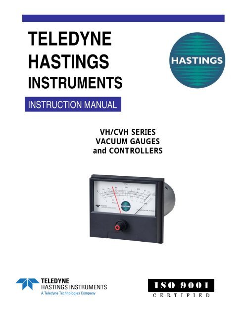
TELEDYNEHASTINGSINSTRUMENTSINSTRUCTION MANUAL<strong>VH</strong>/C<strong>VH</strong> SERIESVACUUM GAUGESand CONTROLLERSISO 9001C E R T I F I E D
Manual Print HistoryThe print history shown below lists the printing dates of all revisions and addenda created for this manual.The revision level letter increases alphabetically as the manual undergoes subsequent updates. Addenda,which are released between revisions, contain important change information that the user shouldincorporate immediately into the manual. Addenda are numbered sequentially. When a new revision iscreated, all addenda associated with the previous revision of the manual are incorporated into the newrevision of the manual. Each new revision includes a revised copy of this print history page.Revision A (Document Number 106-121999)............................................................ December 1999Revision B (Document Number 106-082002)................................................................. August 2002Revision C (Document Number 106-082005) ................................................................ August 2005Revision D (Document Number 106-012006) ............................................................... January 2006Revision E (Document Number 106-082010)................................................................. August 2010Visit www.teledyne-hi.com for WEEE disposal guidance.CAUTION:The instruments described in this manual are available with multiple pin-outs.Ensure that all electrical connections are correct.CAUTION:The instruments described in this manual are designed for INDOOR use only.CAUTION:The instruments described in this manual are designed for Class 2 installationsin accordance with IAW/IPC standards<strong>Hastings</strong> <strong>Instruments</strong> reserves the right to change or modify the design of its equipment withoutany obligation to provide notification of change or intent to change.Manual 106-082010_<strong>VH</strong>_C<strong>VH</strong>-vacuum-gauges Page 2 of 15
Table of Contents1. GENERAL INFORMATION............................................................................................................................................ 41.1. GENERAL INFORMATION ..................................................................................................................................... 41.2. SPECIFICATIONS, <strong>VH</strong> MODELS:.................................................................................................................................... 51.3. SPECIFICATIONS, C<strong>VH</strong> MODELS:................................................................................................................................. 51.4. ACCESSORIES:.............................................................................................................................................................. 51.5. HASTINGS REF REFERENCE TUBE:...............................................................................................................................62. INSTALLATION AND OPERATION............................................................................................................................. 72.1. RECEIVING INSPECTION: .............................................................................................................................................. 72.2. POWER REQUIREMENTS:.............................................................................................................................................. 72.3. GAUGE TUBE INSTALLATION:...................................................................................................................................... 72.4. PANEL MOUNTING:...................................................................................................................................................... 72.5. ELECTRICAL CONNECTION:.......................................................................................................................................... 82.6. OPERATION OF C<strong>VH</strong> CONTROLLERS:........................................................................................................................... 82.7. NOTES ON VACUUM MEASUREMENTS: ........................................................................................................................ 83. THEORY OF OPERATION ........................................................................................................................................... 103.1. METER FACES............................................................................................................................................................ 114. MAINTENANCE.............................................................................................................................................................. 124.1. TROUBLESHOOTING: .................................................................................................................................................. 124.2. CALIBRATION: ........................................................................................................................................................... 124.3. HASTINGS REFERENCE TUBE: .................................................................................................................................... 134.4. AC SUPPLY VOLTAGE: .............................................................................................................................................. 135. SERVICE INFORMATION............................................................................................................................................ 14WARRANTY AND REPAIR.................................................................................................................................................... 155.1. WARRANTY REPAIR POLICY ...................................................................................................................................... 155.2. NON-WARRANTY REPAIR POLICY ............................................................................................................................. 15Manual 106-082010_<strong>VH</strong>_C<strong>VH</strong>-vacuum-gauges Page 3 of 15
1. General Information1.1. GENERAL INFORMATIONThe <strong>Hastings</strong> Model <strong>VH</strong> Vacuum Gauge and Model C<strong>VH</strong> Vacuum Controller are economical analoginstruments combining modular, solid state construction and taut-band meters. Gauge tubes have excellentstability and ruggedness, and provide pressure measurements over the 0-5000 millitorr range for Models<strong>VH</strong>-3, C<strong>VH</strong>-3, and C<strong>VH</strong>-23; or over the 0-50 Torr range for Models <strong>VH</strong>-4, C<strong>VH</strong>-4, and C<strong>VH</strong>-24.The instruments incorporate voltage regulation and operate on 115 VAC or 230 VAC, 50 or 60 cycles. All<strong>VH</strong> and C<strong>VH</strong> instruments are available with dual-scale meter faces which include a millibar scale (seemeter faces, page 8).Environmental tests show that the gauge tube is stable over a wide temperature range. The low operatingtemperature of the directly heated, patented, noble metal thermopile in the gauge tube contributes greatlyto a long, stable life.Use of the <strong>Hastings</strong> improved, directly heated thermopile principle provides a stable, reliable, fast-responsevacuum gauge at a moderate cost that outperforms many instruments costing considerably more.1.1.1. Features:<strong>VH</strong> VACUUM GAUGES• Economical• Ready for Mounting• Rapid Response• Taut-band Meters• Internal Voltage Regulation• Interchangeable, matched gauge tubes• Choice of 115 or 230 volts: field changeableC<strong>VH</strong> VACUUM CONTROLLERS• All features of <strong>VH</strong> Vacuum Gauges• Choice of single or double set point• Automatic contact less control and indication• Fail-safe: loss of power = loss of vacuum• Adjustable control pointer eliminates guessworkin setting control points• Contacts -- SPDT 5 amps, 230 volts AC• Fast control action without "dead zone"• Suitable for 50 or 60 cycle• Plug-in extension cablesManual 106-082010_<strong>VH</strong>_C<strong>VH</strong>-vacuum-gauges Page 4 of 15
1.2. Specifications, <strong>VH</strong> Models:• Power...................................................................................................115/230 VAC, 50/60 Hz• Range, Model <strong>VH</strong>-4 .............................................................................. 0-50 torr or 0-10 mbar• Range, Model <strong>VH</strong>-3 ..................................................................... 0-5000 millitorr or 0-5 mbar• Gauge Tubes ............................................... Model DV-24 for <strong>VH</strong>-4, Model DV-23 for <strong>VH</strong>-3• Tube Connections ....................... DV-24: 1/8" NPT, KF-16, KF-25 DV-23: 1/8" NPT, VCR,.............................................................................................................................. KF-16, KF-25• Cables ............................... ........6-ft.(approx) power cable and 8-ft. gauge tube cable attached.............................................................................................................Extension cables available• Dimensions.......................................................4.12" wide X 3.52" high. Depth required, 3.00"• Gauge Tube Leak Test................................................................................................10-8 sccs• Maximum Pressure...................................................... DV-23 & DV-24 gauge tubes = 50 psig• Maximum Temperature ...............................................DV-23 & DV-24 gauge tubes = 100oC• Weight (approx) ............................................................................................................1.20 oz.1.3. Specifications, C<strong>VH</strong> Models:• Power...................................................................................................115/230 VAC, 50/60 Hz• Range, Models C<strong>VH</strong>-4 and C<strong>VH</strong>-24 ......................................0-50 torr or 0-10 mbar full scale• Range, Models C<strong>VH</strong>-3 and C<strong>VH</strong>-23 ..........................................0-5 torr or 0-5 mbar full scale• Gauge Tubes ..................................... Model DV-24 for C<strong>VH</strong>-4 & C<strong>VH</strong>-24 Model DV-23 for.......................................................................................................................C<strong>VH</strong>-3 & C<strong>VH</strong>-23• Cables .................................................... 6-ft.(approx) power cable, 8-ft. gauge tube cable, and................................................................. 1-ft. cable for each relay contact. Extensions available• Dimensions........................ 5.00" wide X 4.25" high. Depth required, 7" Barrel diameter, 2.75"• Contacts................................................................ Rated 5 amp @ 230 volts AC non-inductive• Control Mode ................................................................... Continuous reading, automatic reset• Weight (approx) ........................................................................................... 3 lb. net, complete1.4. Accessories:1.4.1. Drop-Out Trap DO-2The Model DO-2 is a particle drop-out trap which also provides an effective optical baffle. It has theequivalent of eight 90 degree bends, and protects the gauge tube from flying particles, evaporated metals,etc. The gauge tube threads into the trap, which installs into the existing gauge tube fitting. Simplepiggyback” installation is used. Construction is of monel/nickel plated brass. The DO-2 may be cleanedwith steam, solvent, an air hose; ultrasonic, etc. 1/8" NPT fittings are used; female for gauge tube, male tosystem.1.4.2. Valved Quick Connect, Type OS-V & OS-VRThe OS-V & OS-VR provide a quick-connect O-ring seal fitting for the gauge tube with a toggle type shutoffvalve. They permit removal and replacement of a gauge tube in many systems without “breaking” theentire system to atmospheric pressure. They also permit closing off the tube during the “dirty” portion of acycle. The OS-V & OS-VR install in 1/8" NPT female thread. Type OS-VR is a right-angle pattern valve.Size: 1" x 3" x 3-1/2"; brass construction.Manual 106-082010_<strong>VH</strong>_C<strong>VH</strong>-vacuum-gauges Page 5 of 15
1.4.3. Dual Valved Quick Connect, Type OS-V2The OS-V2 is similar to the OS-V & OS-VR, except it permits use of an additional tube in a secondpressure range, or as a calibration check against a production tube. It features an unused spare ready foruse. The OS-V2 installs in a 1/8" NPT female threaded fitting of an existing gauge tube. It is adjustable forangled or straight installation. Size: 7-1/2" x 1" x 3-3/4"; brass construction.1.4.4. <strong>Hastings</strong> Seal-Nut, Type OS-HThe OS-H is a metal hex nut with a Teflon insert. It threads over a 1/8" NPT male NPT thread and jamsagainst the fitting to provide a dry, non-shredding, reusable vacuum-tight seal. The OS-H eliminates theuse of messy liquid sealant. It may be used to install gauge tubes, quick connects, drop-out traps and other1/8"NPT male fittings in vacuum systems. The OS-H is supplied in packages of 10, 25, 50, and 100.1.4.5. <strong>Hastings</strong> Quick Connects<strong>Hastings</strong> Quick Connects offer an O-ring sealed fitting for <strong>Hastings</strong> and other model gauge tubes with 1/8"pipe stems (.405" OD tubing). They provide a clean, dry, leak-tight seal and permit quick, easy removaland replacement of gauge tubes without wrenches or messy sealants.See Product Bulletin 352 for further information and warnings on <strong>Hastings</strong> Installation Accessories.1.5. <strong>Hastings</strong> Ref Reference Tube:The <strong>Hastings</strong> Reference Tube is an evacuated, sealed vacuum gauge tube accurately calibrated to preciselysimulate a gauge tube at a given operating pressure. It is electrically equivalent to the metal and Glassgauge tubes used with <strong>Hastings</strong> <strong>Instruments</strong>. It permits quick and easy recalibration of <strong>Hastings</strong> VacuumGauge Indicators by merely plugging the instrument into the reference and adjusting the calibration“current set” potentiometer until the instrument reads the pressure noted on the reference. <strong>Hastings</strong>Reference Tubes are available equivalent to each <strong>Hastings</strong> Gauge Tube.Manual 106-082010_<strong>VH</strong>_C<strong>VH</strong>-vacuum-gauges Page 6 of 15
2. INSTALLATION AND OPERATIONThis section is designed to assist in getting a new vacuum gauge or controller into operation as quickly andeasily as possible. Please read the following very thoroughly before attempting to install the instrument.2.1. Receiving Inspection:Carefully unpack the <strong>Hastings</strong> Vacuum Instrument and any accessories that arrive with it. Inspect it for anyobvious signs of damage due to shipment. Immediately advise the carrier who delivered the shipment if anydamage is suspected.Compare each component shipped against the packing list. Ensure that all parts are present (i.e. vacuumgauge, gauge tube, extension cables etc.). Optional equipment or accessories will be listed separately on thepacking list.2.2. Power Requirements:Model <strong>VH</strong> and C<strong>VH</strong> Vacuum <strong>Instruments</strong> can operate on either 50 or 60 Hz AC. Standard <strong>VH</strong> and C<strong>VH</strong>models are set up at the factory to operate on 115 VAC. Units designated with a prefix “E” in the modelnumber (i.e. E<strong>VH</strong>-3) are set up to operate on 230 VAC. NOTE: The supply voltage for each unit can bechanged in the field by changing a jumper on the PC board. See Section 4.4 if this becomes necessary. All<strong>VH</strong> and C<strong>VH</strong> instruments come equipped with a standard three-prong plug. An “ON-OFF” switch can beinstalled in the following manner. Cut the power cable to the desired length, and discard the plug. Connectthe black lead to a properly rated single-pole, single-throw switch; connect the white lead to common(neutral), and connect the green lead to ground.2.3. Gauge Tube Installation:The type DV-23 gauge tube has a nickel-plated tube body with a standard 1/8" NPT male pipe thread, orstainless steel body with a VCR, KF-16, or KF-25 connection. The octal base is color coded orange. TheDV-24 has a white base. All tubes of the same type are matched and interchangeable.When mounting the gauge tube in the vacuum system, the preferred orientation is a vertical position withthe open end pointing down, to prevent accumulation of liquid and solid particles.The gauge tube is installed in the vacuum system by screwing it into an opening having standard 1/8" NPTpipe threads. The connection should be made vacuum-tight around the threads by solder, Teflon tape or<strong>Hastings</strong> Seal Nuts.The stem of the gauge tube has a smooth section above the threads for use with an O-ring coupling.<strong>Hastings</strong> Quick Connect Couplings, available as accessories, offer a simple and rapid method of installingthe gauge tube in the vacuum system. These couplings, machined from solid brass stock, are available forseveral types of system connections.The VCR connections consist of a VCR female nut, 9/16-18 UNF female threads w/.75 hex, with Cajon®#SS-4-VCR-3 and #SS-4-VCR-1. The gasket is not provided. Follow Cajon® instructions for makingconnection of these gauge tubes to the vacuum system. The KF connections are made using a centering O-ring and clamp (neither O-ring nor clamp are provided).2.4. Panel Mounting:If the vacuum instrument is a panel mount version, see the Mounting Templates, Section 6.0, for the panelcutout dimensions. CAUTION: The meter has a taut-band type movement and is not sealed. To preventdamage to the meter, the indicator should not be mounted on a panel which is subjected to motor vibrationor a dust-laden environment. The meter face may be cleaned with water-dampened tissue. DO NO NOTUSE SOLVENTS TO CLEAN THE METER FACE..Manual 106-082010_<strong>VH</strong>_C<strong>VH</strong>-vacuum-gauges Page 7 of 15
2.5. Electrical Connection:After the gauge tube is installed in the system, and the meter is installed in the panel, the two are connectedtogether by plugging the gauge tube cable into the tube base. If the standard connecting cable furnishedwith your instrument is inadequate for your application, gauge tube extension cables type VP-(length)-VSare available in lengths of 12, 25, 50, and 100 feet. DO NOT USE HASTINGS EXTENSION CABLESOTHER THAN TYPE VP-VS SINCE THE PIN CONNECTIONS AND NUMBER OF WIRES DIFFERS.Gauges and controllers are factory calibrated to include extensions when cables are ordered with theinstrument at time of purchase. If extensions are added later without recalibration, an error ofapproximately 4% will exist for each additional 25 feet of #18, 4-conductor cable.After the gauge tube is plugged into the cable, apply the appropriate AC voltage. The <strong>Hastings</strong> VacuumGauge or Controller is now reading the vacuum in the system. If the gauge tube is not under vacuum, theneedle on the indicator should move up to read “ATM” (atmospheric pressure). When the power is turnedoff, the needle should return to the center dot near full scale, indicating that the power supply and thegauge tube are operating properly.2.6. Operation of C<strong>VH</strong> Controllers:To check control circuits, turn the power on and move the set pointer knob on the front of the meter untilthe pointer passes the needle. As the pointer passes the needle, listen for the relay to operate. This indicatesthat the control circuit is operating properly. For double set-point controllers, both set-points should bechecked.The <strong>Hastings</strong> Vacuum Controller features a contactless, optical meter-relay which provides controlthroughout the entire scale. Set the adjustable control arm by moving the set-pointer to the desiredpressure on the meter. As the pressure increases and the indicating needle passes the set-point, the relay isde-activated.The meter continues to indicate pressure over the entire scale independent of relay operations. Externalconnections to the relay controls are accomplished by means of a one-foot long 3-conductor cable attachedto the rear of the meter housing. The cable has a 3-pin male connector for use by the customer.The double-point controllers have two set-points. Either set-point can be adjusted over 100% of scale, butwill not cross over the other set-point and reverse the “LOW” and “HIGH” set-point designations. A greenpointer indicates the position of the “LOW” set-point and is controlled by the green part of the dual adjustknob on the front of the meter. A red pointer indicates the position of the “HIGH” set-point and iscontrolled by the red part of the dual-adjust knob. For double-point controllers, two cables (“LOW” and“HIGH”) are attached to the rear of the meter housing.2.7. Notes on Vacuum Measurements:2.7.1. Outgassing<strong>Hastings</strong> Gauge Tubes are made of materials that have been proven by years of usage to be relatively freefrom outgassing. However, all surfaces of glass and metal that are exposed to the vacuum system liberategases and vapors that were previously adsorbed during exposure to the atmosphere. If the surfaces arecontaminated with foreign matter, this outgassing may be much more persistent than if the surfaces areclean.The possibility of outgassing must be considered in checking the accuracy of <strong>Hastings</strong> Gauges or inchecking for leaks. This is especially important when working with pressures of less than 10 microns ofmercury. In this range of pressures, outgassing from surfaces in a newly evacuated system may flood theenclosure. Also, if the system is being pumped continuously, gauges spaced at different distances from thepump will register different pressures. For reliable comparison of different vacuum gauges, it is necessarythen to insure that the vacuum system be free of any outgassing or other sources of apparent leaks. This canbest be determined by closing the system off from the pumps and observing if there is any rise in pressurewithin the range of interest.2.7.2. IngassingIngassing is an effect opposite to outgassing, and can also lead to erroneous readings. Ionization gaugesexhibit a kind of pumping action that tends to clean up residual gases in certain ranges of pressure, andthereby lowers the pressure. Also, if a cold trap is in a closed system, the total pressure may changeconsiderably while condensable vapors such as water, carbon dioxide and mercury are being condensed.Manual 106-082010_<strong>VH</strong>_C<strong>VH</strong>-vacuum-gauges Page 8 of 15
2.7.3. Effect of Thermal mal ConductivityAll <strong>Hastings</strong> Vacuum <strong>Instruments</strong> are originally calibrated in dry air. Since this calibration is a function ofthermal conductivity, any gas having a thermal conductivity different from that of air will also have adifferent calibration. Nomograms are provided on pages 26, 27, & 28 to correct indicated pressures toactual pressures for several of the common gases encountered in vacuum work.2.7.4 Effect of System ConductanceEach element that makes up a vacuum system has associated with it a certain conductance (this is theopposite of resistance). For example, baffles, connecting tubing, and sharp turns can all cause pressuredrops throughout the system during pumping and during the time the system is reaching static equilibrium.It is not an uncommon occurrence to measure different pressures at different locations in a vacuum system.In checking the calibration of any vacuum gauge, care must be taken to insure that the gauge and thereference are at the same pressure.Manual 106-082010_<strong>VH</strong>_C<strong>VH</strong>-vacuum-gauges Page 9 of 15
3. THEORY OF OPERATIONTwo noble wires, welded in the center, formthermocouples (refer to Figure 3.1). The ends are weldedto reference junctions and a constant alternating currentfrom the dual secondary’s of the transformer heats eachwire independently to the same temperature rise aboveambient. The d-c thermoelectric EMF generated by thistemperature rise is dependent upon the applied power andthe cooling effect (thermal conductivity) of thesurrounding gas. As the pressure changes, the thermalconductivity changes, causing a change in generatedEMF. Since the reference junctions are at ambienttemperature and the temperature rise above ambient is thesame at constant heating power and constant pressure,compensation for temperature is an inherent characteristicof the device.FIG 3.1If the secondaries of the transformer are balanced and the noble wiresare welded in the midpoint, this results in a balanced bridge for ACvoltage. The only voltage between the center taps of the transformersis the DC EMF generated by the thermocouple junction. The DCvoltage is applied to a millivoltmeter which is scaled in units ofpressure to directly read the absolute pressure in the tube. See Figure3.2 and dual scale meter faces shown on the next page.FIG 3.2Manual 106-082010_<strong>VH</strong>_C<strong>VH</strong>-vacuum-gauges Page 10 of 15
3.1. Meter FacesModels <strong>VH</strong>-3 & E<strong>VH</strong>-3Uses Type DV-23 Gauge TubeModels <strong>VH</strong>-4 & E<strong>VH</strong>-4Uses Type DV-24 Gauge TubeModels C<strong>VH</strong>-3, C<strong>VH</strong>-23, EC<strong>VH</strong>-3 & EC<strong>VH</strong>-23Uses Type DV-23 Gauge TubeModels C<strong>VH</strong>-4, C<strong>VH</strong>-24, EC<strong>VH</strong>-4 & EC<strong>VH</strong>-24Uses Type DV-24 Gauge TubeManual 106-082010_<strong>VH</strong>_C<strong>VH</strong>-vacuum-gauges Page 11 of 15
4. MAINTENANCEThis section contains service and calibration information. Some portions of the instrument are delicate.Use extreme care when servicing the vacuum gauge or controller. The potentiometer positions and theelectrical components referred to in the troubleshooting section can be found in Section 6.0 on theelectrical component layout drawing.4.1. Troubleshooting:If the gauge or controller fails to operate, the following procedure for troubleshooting will be helpful.4.1.1. Electrical ConnectionsCheck the plug, power source, and any switches to be sure that power is being applied to the circuit.Check the gauge tube cable and socket connections at the gauge tube. The voltage between pins 2 and 4 orpins 6 and 8 should be approximately 0.2 volts AC. If a circuit failure has occurred, return the instrumentto the factory for repairs.4.1.2. Gauge TubesThe most common cause of failure is the gauge tube. The gauge tube can be checked quickly bysubstituting a new clean gauge tube in the system. The indication obtained with the new tube can then becompared with the indication obtained with the old tube.The gauge tube can be checked for physical damage (broken couples, etc.) by removing the tube from thesystem and checking for continuity between pins 2 and 4 and pins 6 and 8.DO NOT ATTEMPT TO CHECK FOR CONTINUITY WITH THE GAUGE TUBE EVACUATED ORDAMAGE TO THE TUBE MAY RESULT. (Note that a <strong>Hastings</strong> Reference tube is always evacuated). If continuity(approximately 5 ohms) does not exist between the specified pins, replace the tube with a new gauge tube.A contaminated gauge tube can be cleaned by carefully filling the tube with a solvent such as a CFC freecleaner. Rock the tube gently (do not shake) to loosen contamination. Rinse the tube with alcohol and bakeat approximately 150oF to de-gas.4.1.3. Defective MetersIf the meter is damaged, replacement meters are available from <strong>Hastings</strong> <strong>Instruments</strong>. Refer to the serviceinformation in Section 5.0 for the appropriate parts numbers.4.2. Calibration:<strong>Hastings</strong> Vacuum Gauges and Vacuum Controllers are calibrated at the factory and seldom needadjustment. Calibration shifts are usually caused by damaged or contaminated gauge tubes, or gauge tubeextensions not included in the factory calibration. Refer to the sections on “TROUBLESHOOTING”(above) and “ELECTRICAL CONNECTION” (page 5) before proceeding with recalibration.4.2.1. Calibration Procedure1. With the power off, adjust the small slotted mechanical zero screw on the front of the meter so theindicating needle is over the center dot (<strong>VH</strong>-4, C<strong>VH</strong>-4, and C<strong>VH</strong>-24 single dot) near full scale.2. A reference pressure of less than one micron must be established to set the gauge for zero pressure. Theexact pressure need not be known so long as it is below one micron. With the power on, pump the gaugetube for 15-30 minutes to eliminate any outgassing from the tube.3. A trimpot is mounted inside the aluminum cover and is accessible through a small hole on the side of thecover. Adjust the trimpot until the indicator reads zero pressure.Manual 106-082010_<strong>VH</strong>_C<strong>VH</strong>-vacuum-gauges Page 12 of 15
4.2.2. Alternate ProcedureA reliable pressure standard, such as a capacitance manometer or a liquid nitrogen trapped McLeod typegauge, may be used if the system pressure is greater than one micron or if more than one calibration pointis desired. To avoid outgassing, do not use an untrapped McLeod, a chemical-trapped McLeod, or Tygontubing for calibration.Adjust the calibration trimpot so the meter indicates the same pressure as the reference.4.3. <strong>Hastings</strong> Reference Tube:The <strong>Hastings</strong> Reference Tube, Type DB-33, is an evacuated, sealed tube which is accurately calibrated.The DB-33 Reference Tube connects to the gauge tube cable octal socket, and simulates a DV-23 GaugeTube under the designated pressure. Adjust the calibration trimpot so the meter indicates the pressuremarked on the reference tube. For models using the DV-24 Gauge Tube, use only a <strong>Hastings</strong> Type DB-44Reference Tube.4.4. AC Supply Voltage:The standard vacuum instruments (<strong>VH</strong> and C<strong>VH</strong> models) are set up for operation on 115 VAC. Themodels with a leading “E” in the model number (E<strong>VH</strong>-3, E<strong>VH</strong>-4, EC<strong>VH</strong>-3, EC<strong>VH</strong>-23, EC<strong>VH</strong>-4, EC<strong>VH</strong>-24) are set up for operation on 230 VAC at the factory. If operation of a <strong>VH</strong> instrument on another supplyvoltage (different than the factory setting) is desired, the voltage can be changed in the field). This willrequire recalibration of the meter, however. Follow the procedure below to change the supply voltage. Ifoperation of a C<strong>VH</strong> instrument on another supply voltage (different than the factory setting) is desired, youmust consult your factory representative.1. Remove all AC supply voltage from the unit.2. Remove strain reliefs from gauge and power cables.3. Remove two 1/4-28 screws from back of rear cover.4. Pull rear cover off unit.5. Locate jumper P1. If operation on 115 VAC supply is desired, installjumper over both pins of P1. If operation on 230 VAC supply isdesired, install jumper over one pin as shown in Fig. 4.1.6. Re-assemble unit.7. Adjust mechanical zero on front of meter so the indicating needle isover the center dot (<strong>VH</strong>-4, single dot) near full scale.FIG 4.18. Return AC power to the unit and allow it to warm up for a fewminutes.9. Recalibrate using calibration procedure, Sections 4.2.1 and 4.2.2; or use a reference tube as mentionedin Section 4.3.Manual 106-082010_<strong>VH</strong>_C<strong>VH</strong>-vacuum-gauges Page 13 of 15
5. SERVICE INFORMATIONThe following is a list of the available replacement parts and their factory stock numbers:MODEL NO. STOCK NO. DESCRIPTIONDV-23 55-73 Gauge Tube for all <strong>VH</strong>-3, C<strong>VH</strong>-3, & C<strong>VH</strong>-23 modelsDV-24 55-89 Gauge Tube for all <strong>VH</strong>-4, C<strong>VH</strong>-4, & C<strong>VH</strong>-24 modelsDB-33 55-106 Reference Tube for all <strong>VH</strong>-3, C<strong>VH</strong>-3, & C<strong>VH</strong>-23 modelsDB-44 55-107 Reference Tube for all <strong>VH</strong>-4, C<strong>VH</strong>-4, & C<strong>VH</strong>-24 modelsMeter 55-74 Meter for all <strong>VH</strong>-3, C<strong>VH</strong>-3, & C<strong>VH</strong>-23 modelsMeter 55-88 Meter for all <strong>VH</strong>-4, C<strong>VH</strong>-4, & C<strong>VH</strong>-24 modelsTo place an order or obtain information concerning replacement parts, contact the factory or our localmanufacturer’s representative in your area. See below, or this manual’s last page for the address or phonenumber. When ordering, include the following information:• Instrument model number• Part description• <strong>Hastings</strong> part numberManual 106-082010_<strong>VH</strong>_C<strong>VH</strong>-vacuum-gauges Page 14 of 15
6. Warranty and Repair6.1. Warranty Repair Policy<strong>Hastings</strong> <strong>Instruments</strong> warrants this product for a period of one year from the date of shipment to be freefrom defects in material and workmanship. This warranty does not apply to defects or failures resultingfrom unauthorized modification, misuse or mishandling of the product. This warranty does not apply tobatteries or other expendable parts, or to damage caused by leaking batteries or any similar occurrence.This warranty does not apply to any instrument which has had a tamper seal removed or broken.This warranty is in lieu of all other warranties, expressed or implied, including any implied warranty as tofitness for a particular use. <strong>Hastings</strong> <strong>Instruments</strong> shall not be liable for any indirect or consequentialdamages.<strong>Hastings</strong> <strong>Instruments</strong>, will, at its option, repair, replace or refund the selling price of the product if<strong>Hastings</strong> <strong>Instruments</strong> determines, in good faith, that it is defective in materials or workmanship during thewarranty period. Defective instruments should be returned to <strong>Hastings</strong> <strong>Instruments</strong>, shipment prepaid,together with a written statement of the problem and a Return Material Authorization (RMA) number.Please consult the factory for your RMA number before returning any product for repair. Collect freightwill not be accepted.6.2. Non-Warranty Repair PolicyAny product returned for a non-warranty repair must be accompanied by a purchase order, RMA form anda written description of the problem with the instrument. If the repair cost is higher, you will be contactedfor authorization before we proceed with any repairs. If you then choose not to have the product repaired, aminimum will be charged to cover the processing and inspection. Please consult the factory for your RMAnumber before returning any product repair.TELEDYNE HASTINGS INSTRUMENTS804 NEWCOMBE AVENUEHAMPTON, VIRGINIA 23669 U.S.A.ATTENTION: REPAIR DEPARTMENTTELEPHONE (757) 723-6531TOLL FREE 1-800-950-2468FAX (757) 723-3925E MAILhastings_instruments@teledyne.comINTERNET ADDRESS http://www.teledyne-hi.comRepair Forms may be obtained from the “Information Request” section of the <strong>Hastings</strong> <strong>Instruments</strong> website.Manual 106-082010_<strong>VH</strong>_C<strong>VH</strong>-vacuum-gauges Page 15 of 15