Series MSZ 3-Position Rotary Table - SMC
Series MSZ 3-Position Rotary Table - SMC
Series MSZ 3-Position Rotary Table - SMC

You also want an ePaper? Increase the reach of your titles
YUMPU automatically turns print PDFs into web optimized ePapers that Google loves.
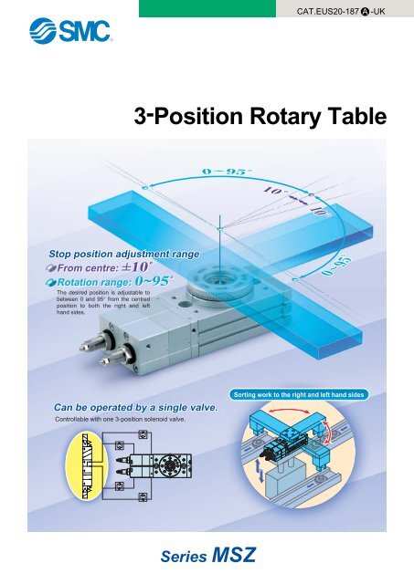
CAT.EUS20-187 A-UK3-<strong>Position</strong> <strong>Rotary</strong> <strong>Table</strong>Stop position adjustment rangeFrom centre: ±10˚Rotation range: 0~95˚The desired position is adjustable tobetween 0 and 95° from the centredposition to both the right and lefthand sides.Can be operated by a single valve.Controllable with one 3-position solenoid valve.Sorting work to the right and left hand sides<strong>Series</strong> <strong>MSZ</strong>
Example of Stop <strong>Position</strong> SettingsAngle is adjustable as shown below. (CCW: Counterclockwise, C: Centre, CW: Clockwise)CCCCCCWCWCWCCWCCWCWCCWCWLeft 90°: Right 90° Left 45°: Right 45°Left 90°: Right 30°Left 60°: Right 90°Working PrincipleThis example uses a 3-position 5-port solenoid valve(pressure centre). When air is supplied to all ports afterthe solenoid valve is in a pressure-center position, thepistons for rotary operation do not have any thrust, asthe pressure on both sides is equal, and the pistons forrotary operation move to the centre position due to thethrust of the pistons for centre stop. When all of thepistons (centre stop and rotary operation) are in contactwith each other, the piston system stops.Piston for centre stopExhaustSupplySupplyEnd of counterclockwise directionPiston for rotary operationCentre positionSupplySupplyEnd of clockwise directionExhaustA load can be mounted directly on the table.A High-precision model is also available in addition to the basic model.Basic model: <strong>MSZ</strong>BHigh-precision model: <strong>MSZ</strong>ARolling bearingHigh-precisionbearingModelSizeTorque (N·m)Port sizeBasic<strong>MSZ</strong>BHigh-precision<strong>MSZ</strong>A102030501235M5Features 1
<strong>Series</strong> <strong>MSZ</strong>Model SelectionModel Selection Procedure Formula Selection Example12Operating conditionsEvaluate the operating conditionsaccording to the mounting position.Vertical MountingRequired torqueConfirm the type of load as shownbelow, and select an actuator thatsatisfies the required torque.. Static load: Ts. Resistance load: Tf Load types. Inertial load: TaHFrM=Fr·LHorizontal MountingLFSM=FS·HGG. Model used. Operating pressure. Mounting orientation. Load typeStatic load: Ts (N⋅m)Resistance load: Tf (N⋅m)Inertia load: Ta (N⋅m). Load configuration. Rotation time t (s). Rotation angle θ (rad). Load mass m (kg). Distance between central axis andcentre of gravity H (m). Mass point distance L (m)Effective torque TsEffective torque (3 to 5) ⋅ TfEffective torque 10 ⋅ TaEffective torqueHG<strong>Rotary</strong> table: <strong>MSZ</strong>B50A, Pressure: 0.5 MPaMounting orientation: VerticalLoad type: Inertial load TaLoad configuration: 0.1 m x 0.06 m (Rectangular plate)Rotation time t: 0.3s, Rotation angle: 90 Load mass m: 0.4 kgDistance between centralaxis and centre of gravity H: 0.04 mInertial load.10 x Ta = 10 x Ι x ω= 10 x 0.00109 x (2 x ( / 2) / 0.3 2 )= 0.380 N⋅m Effective torque OKNote) I substitutes for the value for inertial moment.ba3Rotation timeConfirm that it is within theadjustable range of rotation time.0.2 to 1.0 s / 90 0.3 s / 90 OK4Allowable loadConfirm that the radial load, thrustload and moment are within theallowable ranges.Thrust load: m x 9.8 Allowable loadMoment: m x 9.8 x H Allowable momentAllowable load0.4 x 9.8 = 3.92 N < Allowable load OK0.4 x 9.8 x 0.04 = 0.157 N⋅m0.157 N⋅m < Allowable moment OK5Inertial momentFind the load's inertial moment"Ι" for the energy calculation.Ι = m x (a 2 + b 2 ) / 12 + m x H 2Inertial momentΙ = 0.4 x (0.10 2 + 0.06 2 ) / 12 + 0.4 x 0.04 2= 0.00109 kg⋅m 26Kinetic energyConfirm that the load's kineticenergy is within the allowable value.1 / 2 x Ι x ω 2 Allowable energyω = 2θ / t (ω: Terminal angular velocity)θ: Rotation angle (rad)1/ 2 x 0.00109 x (2 x ( / 2) / 0.3) 2= 60 mJ Allowable energy OKt : Rotation time (s)Allowable kinetic energy/Rotation timeFront matter 1
<strong>Series</strong> <strong>MSZ</strong>Effective TorqueSize10203050OperatingdirectionEndCentreCentreEndEndCentreCentreEndEndCentreCentreEndEndCentreCentreEnd0.20.380.290.720.621.090.911.830.30.600.501.141.011.721.492.830.40.830.701.551.402.362.073.84Operating pressure (MPa)0.51.060.901.971.783.002.654.844.750.61.281.102.392.173.633.235.845.740.71.511.302.812.564.273.816.856.740.81.731.513.222.954.904.397.857.730.91.961.713.643.345.544.978.858.72Unit: N·m12.181.914.063.736.185.559.859.72Note) Effective torque values are representative values and not to be considered as guaranteed values.Torque changes depending on the rotating direction. Please refer to the figure below for the rotating directions.Load TypeStatic load: TsA load as represented by the clamp which requiresa pressing force onlyDuring examination if it is decided to consider the mass of( the clamp itself in the drawing below, it should be regardedas an inertial load.)(Example)lClampF: Pressing force (N)Static torque calculationShaftcentreTs = F x l (N⋅m)Allowable LoadDo not allow the load and moment applied to the table to exceed theallowable values shown in the table below.(Operation beyond the allowable values can cause adverse effects on theservice life, such as play in the table and loss of accuracy.)Size10203050Allowableradial load (N)78147196314EndEndCentre86166233378CentreEnd74137197296Allowable thrust load (N)(a)Centre74137197296CentreEnd78137363451(b)107197398517Allowablemoment (N⋅m)High precisionHigh precisionHigh precisionBasic type Basic type Basic type Basic typetypetypetype(a)(b)EndCentreEnd2.44.05.39.7High precisiontype2.94.86.412.0Resistance load: TfA load that is affected by external forces such asfriction or gravitySince the aim is to move the load, and speedadjustment is necessary, allow an extra margin of 3to 5 times for the effective torque.∗Actuator effective torque (3 to 5) TfDuring examination if it is decided to consider the mass ofthe lever itself in the drawing below, it should be regardedas an inertial load.( )(Example)Mass mMovementLoadLeverFriction coefficient µF = µ mgStatic torque calculationTf = F x l (N⋅m)g = 9.8 m/s 2Inertial load: TaA load that must be rotated by the actuatorSince the aim is to rotate the inertial load, andspeed adjustment is necessary, allow an extramargin of 10 times or more for the effectivetorque.∗Actuator effective torque S . Ta(S is 10 times or more).Ta = Ι ⋅ (N⋅m)LoadlShaftcenterΙ: Inertial momentRefer to Front matter 3..: Angular acceleration. 2θ = (rad/s 2 )t 2θ: Rotation angle (rad)t: Rotation time (s)<strong>Rotary</strong> actuatorFront matter 2
Model selection <strong>Series</strong> <strong>MSZ</strong>Inertial Moment Formula (Calculation of Inertial Moment Ι)(1) Thin shaft (2) Thin shaft (3) Thin rectangular plate (4) Thin rectangular plate(Rectangular parallelepiped) (Rectangular parallelepiped)<strong>Position</strong> of rotational axis:Perpendicular to the shaftthrough one end<strong>Position</strong> of rotational axis:Through the shaft's centre ofgravity<strong>Position</strong> of rotational axis:Through the plate's centre ofgravityΙ: Inertial moment kg⋅m 2 m: Load mass kg<strong>Position</strong> of rotational axis:Perpendicular to the platethrough one of its points (alsothe same in case of a thickerplate)Ι = m1 ⋅ +m2 ⋅3a1 2 a2 23Ι = m ⋅a 212Ι = m ⋅a 212Ι = m1 ⋅+ m2 ⋅4a1 2 + b 2124a2 2 + b 212(5) Thin rectangular plate(Rectangular parallelepiped) (6) Cylinder(Including thin round plate)<strong>Position</strong> of rotational axis:Through the centre of gravity andperpendicular to the plate (alsothe same in case of a thickerplate)<strong>Position</strong> of rotational axis:Centre axis(7) Solid sphere<strong>Position</strong> of rotational axis:Diameter(8) Thin round plate<strong>Position</strong> of rotational axis: DiameterΙ = m ⋅a 2 + b 212Ι = m ⋅r 2 2rΙ = m ⋅ 225Ι = m ⋅r 24(9) Load at lever end(10) Gear transmissionNumber of teeth= aΙ = m1 ⋅ + m2 ⋅ a2 2 + K3(Example) When shape of m2 is a sphere,refer to (7), and K = m2 ⋅ 2r25a1 21. Find the inertial moment ΙB for therotation of shaft (B).2. Next, ΙB is entered to find ΙA the inertialmoment for the rotation of shaft (A) asaΙA = ( ) 2 ⋅ ΙBbKinetic Energy/Rotation TimeNumber of teeth= bEven in cases where the torque required for rotation of the load is small, damage to internal parts may result from theinertial force of the load.Select models giving consideration to the load's inertial moment and rotation time during operation.(The inertial moment and rotation time charts can be used for your convenience in making model selections on Frontmatter 4.)(1) Allowable kinetic energy and rotation time adjustment rangeFrom the table below, set the rotation time within the adjustment range for stable operation. Note that operation exceeding therotation time adjustment range, may lead to sticking or stopping of operation.Size10203050Allowable kinetic energy (mJ)7254881Rotation time adjustment rangefor stable operation (s/90 )0.2 to 1.0(2) Inertial moment calculationSince the formula for inertial moment differ depending on the configuration of the load, refer to the inertial moment calculationformula on this page.Front matter 3
<strong>Series</strong> <strong>MSZ</strong>Kinetic Energy/Rotation Time(3) Model selection Select models by applying the inertial moment and rotation time which have been found to the chart below.0.10.01<strong>MSZ</strong>50AInertial moment (kg·m 2 )0.0010.0001<strong>MSZ</strong>30A<strong>MSZ</strong>20A<strong>MSZ</strong>10A0.000010.20.30.50.71.0Rotation time (s/90°)Rotation Accuracy: Displacement Values at 180° (Reference values)Rotating amount of table topRotating amount of table sidemmMeasuring plate <strong>MSZ</strong>A <strong>MSZ</strong>BRotating amount of table topRotating amount of table side0.030.030.10.1Values in the table are actual values and not guaranteed values.Front matter 4
Model selection <strong>Series</strong> <strong>MSZ</strong><strong>Table</strong> Displacement (Reference values)• The following graphs show the displacementat point A, which is 100 mm away from thecentre of rotation, where the load is applied.Arm100ALoadDisplacement<strong>MSZ</strong>10A<strong>MSZ</strong>20A300Displacement (µm)40035040302010<strong>MSZ</strong>B10A (Basic type)<strong>MSZ</strong>A10A (High precision type)Displacement (µm)25020019040302010<strong>MSZ</strong>A20A (Basic type)<strong>MSZ</strong>A20A (High precision type)05101520253001020304050Load (N) Load (N)<strong>MSZ</strong>30A<strong>MSZ</strong>50A300Displacement (µm)250200150130<strong>MSZ</strong>B30A (Basic type)Displacement (µm)20015012050<strong>MSZ</strong>B50A (Basic type)50<strong>MSZ</strong>A30A (High precision type)<strong>MSZ</strong>A50A(High precision type)010203040506070020406080100120Load (N) Load (N)Front matter 5
<strong>Rotary</strong> <strong>Table</strong>Air ConsumptionAir consumption is the volume of air which is expended by the rotary actuator’s reciprocal operation insidethe actuator and in the piping between the actuator and the switching valve, etc. This is necessary forselection of a compressor and for calculation of its running cost.QCR = V xP+0.10.1x 10 –3 ···(1)PQCP = a x l x0.1x 10 –6···(2)QCR = Amount of air consumption of rotary actuator[l (ANR)]QCP = Amount of air consumption of tube or piping[l (ANR)]V = Inner volume of the rotary table [cm 3 ]P = Operating pressure[MPa]l = Length of piping[mm]a = Inner sectional area of piping [mm 2 ]To select a compressor, it is important to select one that hasplenty of margin to accommodate the total air volume that isconsumed by the pneumatic actuators that are locateddownstream. The total air consumption volume is affected by theleakage in the tube, the consumption in the drain valves and pilotvalves, as well as by the reduction in air volume due to reducedtemperature.FormulaQc2 = Qc x n x No. of actuators x Margin rateQc2 = Amount of exhaust air from a compressorn = Actuator oscillations per minute[l /min (ANR)]Internal Cross Section of Tubing and Steel PipingInternal volume changes depending on the rotating direction(refer to the figure shown in the lower right). Because of this, toobtain the total air consumption, first calculate the airconsumption of each stroke respectively by using formula (1),then add up each result.Air in the tubing is only consumed when the table rotates fromend to centre. The air consumption in the tubing can be obtainedby using formula (2).The internal volume for each rotating direction and the airconsumption at each operating pressure calculated using formula(1) are shown in the table below.NominalT0425T0604TU 0805T08061/8BT1075TU 1208T12091/4BTS 16123/8BT16131/2B3/4B1B[Calculation example]Size: 10 Operating pressure: 0.5 MPa Inner sectional area of piping: 12.6 mm 2Lengh of piping: 1000mm Stroke: Centre CounterclockwiseCentreClockwiseCentreTotal air consumption, Q1, is obtained by adding up the air consumption of each stroke,which is shown in the table below.Air ConsumptionO.D. (mm)4688—101212—16—16———I.D. (mm)2.54566.57.5899.21212.71316.121.627.6Internal cross sectiona (mm 2 )4.912.619.628.333.244.250.363.666.5113127133204366598Q1 = 0.019 + 0.040 + 0.019 + 0.040 = 0.118 l (ANR)EndCentreEndCentreAir consumed in the tubing is calculated using formula (2), as shown below.0.5Q2 = 12.6 x 1000 x x 100.1= 0.063l (ANR)CentreEnd CentreEndAn entire stroke includes two rotations from end to centre where the air is consumed.Thus, the total air consumption Q of the rotary table and tubing is obtained as shownbelow.EndEndQ = Q1 + Q2 + 2 = 0.244l (ANR)CentreSize10203050OperatingdirectionEndCentreCentreEndEndCentreCentreEndEndCentreCentreEndEndCentreCentreEndRotation90°Inner volume(cm 3 )6.693.1113.26.4020.09.5232.616.20.20.0200.0090.0400.0190.0600.0290.0980.0490.30.0270.0120.0530.0260.0800.0380.1300.0650.40.0330.0160.0660.0320.1000.0480.1630.081Operating pressure (MPa)0.5 0.60.040 0.0470.019 0.0220.079 0.0930.038 0.0450.120 0.1400.057 0.0670.195 0.2280.097 0.113Air consumption of rotary table: QCR l (ANR)0.70.0540.0250.1060.0510.1600.0760.2610.1300.80.0600.0280.1190.0580.1800.0860.2930.1460.90.0670.0310.1320.0640.2000.0950.3260.1621.00.0740.0340.1450.0700.2200.1050.3580.178Front matter 6
3-<strong>Position</strong> <strong>Rotary</strong> <strong>Table</strong><strong>Series</strong> <strong>MSZ</strong>Size : 10, 20, 30, 50How to OrderHigh precision typeBasic type<strong>MSZ</strong>A 10 A M9B<strong>MSZ</strong>B 10 A M9BSize10203050Number of auto switches- 2 pcs.n “n” pcs.Auto switch- Without auto switch (Built-in magnet)AWith adjustment boltApplicable Auto Switch/Refer to pages 7 to 11 for detailed auto switch specification.TypeReed switchSolid state switchSpecialfunction——Diagnosticindication(2-colour display)Improved waterresistance(2-colour display)ElectricalentryGrommetGrommetIndicatorlightNoYesYesWiring(Output)2-wire3-wire(NPN equiv.)2-wire3-wire (NPN)3-wire (NPN)2-wireLoad voltageDC5V12 V5 V, 12 V12 VAC24 V 5 V, 12 V 100 V or less—24 V3-wire (NPN) 24 V5 V, 12 V3-wire (NPN)2-wire—100 V—Auto switch modelPerpendicularA90VA96VA93VM9NVM9PVM9BVM9NWVM9PWVM9BWV—In-lineA90A96A93M9NM9PM9BM9NWM9PWM9BWM9BA∗∗∗∗ Although it is possible to attach a water resistant auto switch, this is not a water- resistant-type rotary table.∗ Lead wire length symbols: 0.5 m Nil (Example) M9N3 m L (Example) M9NL5 m Z (Example) M9NZ∗ Auto switches marked with a “ ” symbol are produced upon receipt of orders.12 VLead wire length (m) ∗0.5(Nil)—3(L)5(Z)———Applicable loadRelay, PLCIC circuit—— Relay, PLCIC circuit—Relay, PLCIC circuit—1
<strong>Series</strong> <strong>MSZ</strong>SpecificationsSizeFluidMaximum operating pressureMinimum operating pressureAmbient and fluid temperatureCushionRotation angle adjustment rangeCentre position adjustment rangePort size10 20 30 50Air (non-lube)1MPa0.2 MPa0 to 60°C (with no freezing)None0 to 190°±10°M5Allowable Kinetic Energy and Rotation Time Adjustment RangeSizeAllowable kinetic energy (mJ)Rotation time adjustment range for stable operation (s/90°)10720250.2 to 1.030485081If a kinetic energy exceeding the allowable value is applied to the product, it may be damaged and become unusable. Careshould be taken in designing, adjusting and operating the system so that the kinetic energy will not exceed the allowablevalues.WeightSizeBasic type730High precision type 760Note) Excluding the weight of the auto switches.Unit: g10 20 30 50135014501730185026602820Piping and speed conrol1) A single 3-position pressure centre solenoid valve or two 3-port solenoid valves can be used. (Refer to Figures 1 or 2.)2) A meter-out type speed controller is used for ports A and B and a meter-in type speed controller is used for ports C and D.(Figures 1 and 2 show the state at which pressure is applied to ports B and D.)Figure 1 3-position pressure centre solenoid valve: 1 pc.Meter-outMeter-in C port A portFigure 2 3-position solenoid valve: 2 pcs.PMeter-outMeter-in C port A portPMeter-inD portB portPMeter-inD portB portMeter-outMeter-out∗ The table return position under the power-off state changes depending on the solenoid valve type. Please refer to back page 6 for details.3) Figure 3 shows the operational direction and <strong>Table</strong> 1 shows the pressure port and active speed controller for each operation.2Figure 3 Operational directionsCounterclockwise-1Clockwise-2Clockwise-1Counterclockwise-2<strong>Table</strong> 1OperatingClockwise-1Clockwise-2Counterclockwise-1Counterclockwise-2Pressure port and active speed controllerA, C—Pressure portB, D—Speed controllerC portB portD portA port
3-<strong>Position</strong> <strong>Rotary</strong> <strong>Table</strong> <strong>Series</strong> <strong>MSZ</strong>Angle Adjustment1) Stop positions are adjusted with the adjustingbolts shown in Figure 4.q Adjusting bolts “a” and “b” are used foradjusting the rotation ends. Adjusting bolts“c” and “d” are used for adjusting the centreposition.w Figure 5 shows the angle ranges that can beadjusted with each adjusting bolt.Figure 4 Adjusting bolt positionAdjusting bolt cAdjusting bolt aFixing nut2) Angle adjustmentSupply air when adjusting the angle(a low pressure of approx. 0.2 MPa is recommended).q First adjust both rotation end positions.· Apply pressure to ports A and C and toadjust adjusting bolt “b”.· Apply pressure to ports B and D and toadjust adjusting bolt “a”.· Lock the bolts with the fixing nuts after adjustment.w Next, apply pressure to ports A to D toadjust the centre position.· Loosen the fixing nuts for adjusting bolts “c”and “d”.· Tighten adjusting bolts “c” and “d” untilthey are almost hidden completely behindthe fixing nuts (the table can be rotatedmanually).· Follow the appropriate procedure (R or L)shown in <strong>Table</strong> 2.Figure 5Adjusting bolt bAdjusting bolt dAngle adjustment Rangeadjustment range by adjusting boltClockwise rotation end10°bMaximum rotation10°rangeCenter position adjustmentrotation endCounterclockwiseaadjustment range by adjusting boltrange190°<strong>Table</strong> 2R: Clockwise adjustment L: Counterclockwise adjustment1 Manually rotate the table counterclockwise until resistance is felt.rotate the table clockwise until resistance is felt.2345Centre position adjustmentRotate the table clockwise when adjusting bolt “d” is loosened. Set it tothe desired position.Loosen adjusting bolt “c” until resistance is felt.(Make sure that there is no rotation backlash in the table.)Tighten both adjusting bolts “c” and “d” by approx. 45°. Note 1)ManuallyLock adjusting bolts “c” and “d” with fixing nuts. Note 2)Note 1) Since the position of the adjusting bolt can shift with the changing of screw clearance when tightening the fixing nuts.Note 2) If the table has a rotation backlash after tightening the nut, readjust it.Rotate the table counterclockwise when adjusting bolt “c” is loosened.Set it to the desired position.Loosen adjusting bolt “d” until resistance is felt.(Make sure that there is no rotation backlash in the table.)Tighten both adjusting bolts “c” and “d” by approx. 45°. Note 1)Lock adjusting bolts “c” and “d” with fixing nuts. Note 2)Adjusting angle per rotation of angle adjusting screwsize10203050Adjusting bolt a, b(End position adjustment)10.2°9.0°8.2°8.2°Adjusting bolt c, d(Centre position adjustment)5.1°3.6°3.3°4.1°A piping, speed control, and angle adjustment manual is attached to the product.3
<strong>Series</strong> <strong>MSZ</strong>Construction!9!6 @9 @0 !4 !8 @6 !2 #1 t @1 i r w @4<strong>MSZ</strong>AA(High precision type)#4@5!5!7#3!3!1#0@8@2u$2e$1#6 #5 @7 $4 #2 $0 @4 $3 y @3 o !0 q #7#8 #9Component PartsNo.1234567891011121314151617181920212223DescriptionBodyCoverPlateSealPistonPinionSeal retainerGasket (for cover)<strong>Table</strong>Bearing retainerEnd cover (A)End cover (B)Cylinder tube (A)Cylinder tube (B)Tube cover (A)Tube cover (B)Sub piston (R)Sub piston (F)Adjustment bolt (R)Adjustment bolt (F)MagnetWear ringDeep groove ball bearingMaterialAluminium alloyAluminium alloyAluminium alloyNBRStainless steelChrome molybdenum steelAluminium alloyNBRAluminium alloyAluminium alloyAluminium alloyAluminium alloyAluminium alloyAluminium alloyAluminium alloyAluminium alloyCarbon steelCarbon steelCarbon steelCarbon steelMagnetic materialResinBearing steelNo.242526272829303132333435363738394041424344DescriptionBasic typeDeep groove ball bearingHigh precision type Angular contact ball bearingBushingBushingSeal washerPiston sealPiston sealRod sealGasketO-ringO-ringO-ringCompact hexagon nutHexagon nutHexagon socket head set boltHexagon socket head set boltHexagon socket head set boltSize: 10Round head phillips screwSize: 20, 30, 50 Low head cap screwRound head phillips screw No.0CS type snap ringParallel pinSteel ballMaterialBearing steelSPCCSPCCNBRNBRNBRNBRNBRNBRNBRNBRSteel wireSteel wireStainless steelStainless steelStainless steelStainless steelChrome molybdenum steelSteel wireSpring steelCarbon steelStainless steel4
3-<strong>Position</strong> <strong>Rotary</strong> <strong>Table</strong> <strong>Series</strong> <strong>MSZ</strong>DimensionsBasic type/<strong>MSZ</strong>BAViewYA2YB effective depth YC4 x M5(Piping parts)CACCøDDøDøDEeffective depth FBFAHCB2 x JU2 x JVSD(Max ≅ SU)2 x JC depth JDSWB effective depth WCeffective depth FCAAAAW2XB effective depth XCXAWA45°222.5°BCFDQ(UU)øDF (Through)øDGBA8 x WD depth WE(circumference: 8 equivalents)4 x JJ depth 8AX2 x J throughJA counterbore depth JBAVAYAZBBWFHigh precision type/<strong>MSZ</strong>AAøDIøDHøDJSize10203050DH45h860h865h875h8DI46h861h867h877h8DJ20H828H832H835H8DK59910DL15H817H822H826H8FE1015.516.517.5HA18.5262730(mm)UV52.5636776The position table showsthe counterlockwise endwhen adjusted the rotationangle to 180°.HAFEøDK (through)øDL(UV)Size10203050AA24.732.434.739.7A50657080AV14171719AW1718.518.521AX8101012AY78810AZ11.21.21.6BA9.5121215.5BB607684100BC27343750CA78.110.512.4CB71010.512.5CC3850.453.560.6D45h960h965h975h9DD46h961h967h977h9DE20H928H932H935H9DF59910DG15H917H922H926H9FA8101012FB464.55FC32.533FD4.56.56.57.5H13171720J6.88.68.610.5JA11141418(mm)JB6.58.58.510.5Size10203050JCM8 x 1.25M10 x 1.5M10 x 1.5M12 x 1.75JD12151518JJM5M6M6M8JUM4 x 0.5M5 x 0.5M5 x 0.5M6 x 0.75JVM10 x 1M12 x 1.25M12 x 1.25M14 x 1.5Q34374046S132.5168.5184214.5SD SU50 27.363.5 3969 36.478 42.4UU47545766WA WB WC1520.52326.53H94H94H95H93.54.54.55.5WDM5M6M6M8WE8101012WF32434855XA27363945XB3H94H94H95H9XC3.54.54.55.5YA19242833(mm)YB YC3H9 3.54H9 4.54H9 4.55H9 5.55
<strong>Series</strong> <strong>MSZ</strong>Proper Auto Switch Mounting <strong>Position</strong>BAMagnetOperating range propermounting position (Lm/2)Most sensitive positionOperating range ofsingle auto switch (Lm)Size10203050Rotation190°190°190°190°A B Operatingangle θ m2735394945626883Reed switchD-A9, D-A9V90°80°65°50°Hysterisisangle A B Operatingangle θ m10°10°10°10°D-M9W, D-M9WV, D-M9BAL313943534966728790°80°65°50°Solid state switchHysterisisangle A B Operatingangle θ mOperating angle θ m: Value of the operating range Lm of a single auto switch when converted to an axial rotation angle.Hysteresis angle: Value of the auto switch hysteresis when converted to an angle.10°10°10°10°31394353D-M9, D-M9V4966728760°50°50°40°Hysterisisangle10°10°10°10°Detection of the Center <strong>Position</strong>The appropriate mounting position of the centre position detection switch is between dimensions A and B, as shown above.However, since the auto switch turns on in the range of the operating angle (θ m), when one auto switch is used for detecting thecentre position, the switch turns on long before reaching the centre position, as shown in the left figure below.To avoid this, use two switches (as shown in the right figure below) so that the rotation may be detected from both the clockwiserotation end to the centre position and from the counterclockwise rotation end to the centre position.Centre position detecting switch: 1 pc.Centre position detecting switch: 2 pcs.Rotation range ON(CCWM)Rotation range ON(CWM)Rotation range ON(CCWM)Rotation range ON(CWM)Rotation range ONMRotationrange ONRotationrange ONMRotation range ONCCWCWCCWCW: Operating range of auto switch CCW: Counterclockwise M: Centre CW: Clockwise6
<strong>Series</strong> <strong>MSZ</strong>Auto Switch SpecificationsAuto Switch Common SpecificationsTypeLeakage currentOperating timeImpact resistanceInsulation resistanceWithstand voltageAmbient temperatureEnclosureReed switchNone1.2 ms300 m/s 250 MΩ or more at 500 V DC Mega (between lead wire and case)1000 V AC for 1 min.(between lead wire and case)–10 to 60°CIEC529 standard IP67, watertight (JIS C 0920)Solid state switch3-wire: 100 µA or less, 2-wire: 0.8 mA or less1 ms or less1000 m/s 21000 V AC for 1 min.(between lead wire and case)Lead Wire LengthLead wire length indication(Example)D-M9P LLead wire length- 0.5 mL 3 mZ 5 mContact Protection Box/CD-P11, CD-P12D-A9 and D-A9V, type switches do not have internal contact protection circuits.(1)The operated load is an induction load.(2)The length of wiring to the load is 5 m or more.(3)The load voltage is 100 VAC.A contact protection box should be used in any of the above situations.Otherwise the lifetime of the contact may be shortened.Note 1) Lead wire length Z: 5 m applicable auto switchesSolid state switch: All types are produced upon receipt of order.Note 2) For solid state switches with flexible wire specification, add “–61” at theend of the lead wire length.(Example) D-M9PVL- 61Flexible specificationSpecificationsPart No.Load voltageMax. load current∗ Lead wire lengthCD-P11100 V AC 200 V AC25 mA 12.5 mASwitch connection side: 0.5 mLoad connection side: 0.5 mCD-P1224 V DC50 mAInternal CircuitCD-P11Surge absorberChokecoilOUT BrownOUT BlueCD-P12Zener diodeChoke coilOUT (+)BrownOUT (-)BlueDimensionsContact Protection Box/ConnectionTo connect a switch unit to a contact protection box, connect the lead wirefrom the side of the contact protection box marked SWITCH to the leadwire coming out of the switch unit. The switch unit should be kept as closeas possible to the contact protection box with a lead wire that is no morethan 1 metre in length.7
Auto SwitchConnections and ExamplesBasic WiringSolid state 3-wire, NPNSolid state 3-wire, PNP2-wire(Solid state)2-wire(Reed)SwitchmaincircuitBlackBrownBlueLoadSwitchmaincircuitBlackBrownBlueLoadSwitchmaincircuitLoadBrownBlueIndicatorlight,protectioncircuit,etc.LoadBrownBlue(When power supply for switch and loadare separate.)BrownSwitchmaincircuitBlackBlueLoadSwitchmaincircuitBrownLoadBlueIndicatorlight,protectioncircuit,etc.BrownLoadBlueExamples of Connection to PLCSink input specifications3-wire, NPNBlack InputBrownSwitchSource input specifications3-wire, PNPBlackSwitchBrownInputConnect according to the applicablePLC input specifications, as theconnection method will vary dependingon the PLC input specifications.2-wireBlueCOMPLC internal circuit2-wireBlueCOMPLC internal circuitBrownInputBlueInputSwitchSwitchBlueCOMPLC internal circuitBrownConnection Examples for AND (<strong>Series</strong>) and OR (Parallel)3-wireAND connection for NPN output(using relays)Switch 1BrownBlackBlueBrownBlackSwitch 2BlueRelayRelayLoadRelaycontactCOMAND connection for NPN output(performed with switches only)Switch 1Switch 2BrownBlueBrownBlueBlackLoadBlackPLC internal circuitOR connection for NPN outputSwitch 1Switch 2BlueBlueBrownBlackBrownBlackLoad82-wire with 2 switches AND connectionSwitch 1Switch 2BrownBlueBrownBlueLoad= 24 V – 4 V x 2 pcs.= 16 VExample: Power supply voltage is 24 V DCVoltage decline in switch is 4 VWhen two switches areconnected in series, aload may malfunction becausethe load voltagewill decline when in theON state.The indicator lights willlight up if both of the switchesare in the ON state.Load voltage at ON =Power supply Residualvoltage – voltage x 2 pcs.The indicator lights will light up whenboth switches are turned ON.2-wire with 2 switches OR connectionSwitch 1Switch 2BlueBrownBrownBlueLoad voltage at OFF =LoadLeakagecurrentx 2 pcs. x= 1 mA x 2 pcs. x 3 kΩ= 6 VExample: Load impedance is 3 kΩLeakage current from switch is 1 mA(Solid state)When two switchesare connected inparallel, malfunctionmay occur becausethe load voltage willincrease when inthe OFF state.Loadimpedance(Reed)Because there is no currentleakage, the loadvoltage will not increasewhen turned OFF. However,depending on thenumber of switches in theON state, the indicatorlights may sometimes getdark or not light up, becauseof dispersion andreduction of the currentflowing to the switches.
Reed Switch: Direct Mounting StyleD-A90(V)/D-A93(V)/D-A96(V)GrommetElectrical entry: In-lineCautionOperating PrecautionsFix the switch with the existing screwinstalled on the switch body. The switchmay be damaged if a screw other than theone supplied, is used.Auto Switch Internal CircuitD-A90(V)Reed switchContactprotectionboxCD-P11CD-P12OUT (±)BrownOUT (±)BlueAuto Switch SpecificationsPLC: Programmable Logic ControllerD-A90/D-A90V (Without indicator light)Auto switch part no.Applicable loadLoad voltageMaximum load currentContact protection circuit24 V AC/DC or less50 mAD-A90/D-A90VIC circuit, Relay, PLC48 V AC/DC or less40 mANone100 V AC/DC or less20 mAInternal resistance1 Ω or less (including lead wire length of 3 m)D-A93/D-A93V/D-A96/D-A96V (With indicator light)Auto switch part no.Applicable loadD-A93/D-A93VRelay, PLCD-A96/D-A96VIC circuitLoad voltage24 V DC100 V AC4 to 8 V DCNote 3)Load current range 5 to 40 mA5 to 20 mA20 mAand max. load currentContact protection circuitNoneInternal voltagedropIndicator lightD-A93 — 2.4 V or less (to 20 mA)/3 V or less (to 40 mA)D-A93 V — 2.7 V or lessRed LED lights when ON0.8 V or less Lead wiresD-A90(V)/D-A93(V) — Oilproof vinyl heavy-duty cord: ø2.7, 0.18 mm 2 x 2 cores (Brown, Blue), 0.5 mD-A96(V) — Oilproof vinyl heavy-duty cord: ø2.7, 0.15 mm 2 x 3 cores (Brown, Black, Blue), 0.5 mNote 1) Refer to page 7 for reed switch common specifications.Note 2) Refer to page 7 for lead wire lengths.WeightFor details about certified products conforming tointernational standards, visit us at www.smcworld.com.Unit: gD-A93(V)Reed switchLED diodeResistorZenerdiodeBrownBlueContactprotectionboxCD-P11CD-P12OUT (+)BrownOUT (–)BlueModelLead wire length: 0.5 mLead wire length: 3 mDimensionsD-A90/D-A93/D-A96D-A90630D-A90V630M2.5 x 4lSlotted set screwD-A93630D-A93V630D-A96841D-A96V841Unit: mmIndicator lightD-A90 type comes withoutindicator lightD-A96(V)DC (+)LED diodeBrownResistorLoadReverse OUTcurrent BlackpreventiondiodeReed switchDC (–)Blue(+)DC powersupply(–)Most sensitivepositionNote) (1)In a case where the operation load is aninductive load.(2)In a case where the wiring load isgreater than 5 m.(3)In a case where the load voltage is 100VAC.Please use the auto switch with a contactprotection box any of the above mentioned cases.(For details about the contact protection box,refer to page 7.)D-A90V/D-A93V/D-A96VM2.5 x 4l Slotted set screwMost sensitiveposition( ): dimensions for D-A93.Indicator lightD-A90 type comes withoutindicator light9
Solid State Switch: Direct Mounting StyleD-M9N(V)/D-M9P(V)/D-M9B(V)Grommet 2-wire load current isreduced (2.5 to 40 mA) Lead-free UL certified (style 2844) leadcable is used.CautionOperating PrecautionsFix the switch with the existing screwinstalled on the switch body. The switchmay be damaged if a screw other than theone supplied, is used.Auto Switch Internal CircuitD-M9N(V)DC (+)BrownAuto Switch SpecificationsAuto switch part no.Lead wire length(m)0.535D-M9N(V)84168For details about certified products conforming tointernational standards, visit us at www.smcworld.com.PLC: Programmable Logic ControllerD-M9, D-M9V (With indicator light)Auto switch part no.Electrical entry directionD-M9NIn-lineD-M9NVPerpendicularD-M9PIn-lineD-M9PVPerpendicularD-M9BIn-lineD-M9BVPerpendicularWiring type3-wire2-wireOutput typeNPNPNP—Applicable loadPower supply voltageCurrent consumptionIC circuit, Relay, PLC5, 12, 24 V DC (4.5 to 28 V)10 mA or less24 V DC relay, PLC——Load voltageLoad currentInternal voltage drop28 V DC or less40 mA or less0.8 V or less—24 V DC (10 to 28 V DC)2.5 to 40 mA4 V or lessLeakage currentIndicator light100 µA or less at 24 V DCRed LED lights when ON.0.8 mA or less Lead wiresOilproof vinyl heavy-duty cord: ø2.7 x 3.2 ellipse, 0.15 mm 2 ,D-M9B(V)0.15 mm 2 x 2 coresD-M9N(V), D-M9P(V) 0.15 mm 2 x 3 coresNote 1) Refer to page 7 for auto switch common specifications.Note 2) Refer to page 7 for lead wire lengths.WeightDimensionsD-M93.2D-M9P(V)84168D-M9B(V)73863Unit: gUnit: mmSwitchmain circuitOUTBlack6 Most sensitive position22 500 (3000)D-M9P(V)DC (–)BlueMounting screw M2.5 x 4lSlotted set screwIndicator light2.6DC (+)Brown42.82.7Switchmain circuitOUTBlackDC (–)BlueD-M9V22 500 (3000)500 (3000) (5000)D-M9B(V)2.7OUT (+)Brown9.52.6Switchmain circuit4OUT (–)BlueMounting screw M2.5 x 4lSlotted set screw2Indicator light83.24.64102.86Most sensitive position20
2-colour Indication Type, Solid State Switch:Direct Mounting StyleD-M9NW(V)/D-M9PW(V)/D-M9BW(V)GrommetAuto Switch SpecificationsFor details about certified products conforming tointernational standards, visit us at www.smcworld.com.Auto Switch Internal CircuitD-M9NW(V)Switchmain circuitD-M9PW(V)Switchmain circuitD-M9BW(V)DC (+)BrownOUTBlackDC (–)BlueDC (+)BrownOUTBlackDC (–)BlueOUT (+)BrownPLC: Programmable Logic ControllerD-M9W/D-M9WV (With indicator light)Auto switch part no.Electrical entry directionD-M9NWIn-lineD-M9NWVPerpendicularD-M9PWIn-lineD-M9PWVPerpendicularD-M9BWIn-lineD-M9BWVPerpendicularWiring type3-wire2-wireOutput typeNPNPNP–Applicable loadPower supply voltageCurrent consumptionIC circuit, Relay, PLC5, 12, 24 V DC (4.5 to 28 VDC)10 mA or less24 V DC relay, PLC––Load voltageLoad current28 V DC or less40 mA or less–80 mA or less24 V DC (10 to 28 V DC)5 to 40 mA1.5 V or lessInternal voltage(0.8 V or less at 10 mAdropload current)0.8 V or less4 V or lessLeakage current100 µA or less at 24 V DC0.8 mA or lessIndicator lightDimensionsD-M9WOperating position .......... Red LED lights upOptimum operating position .......... Green LED lights up Lead wiresOilproof vinyl heavy-duty cord: ø2.7, 0.15 mm 2 x 3 cores (Brown, Black, Blue),0.18 mm 2 x 2 cores (Brown, Blue), 0.5 mNote 1) Refer to page 7 for auto switch common specifications.Note 2) Refer to page 7 for lead wire lengths.WeightAuto switch part no.0.5Lead wire length3(m)526D-M9NW(V)73456Most sensitive positionMounting screw M2.5 x 4lSlotted set screwIndicator lightD-M9PW(V)73456ø2.72.64Unit: gD-M9BW(V)73252Unit: mmSwitchmain circuitOUT (–)BlueD-M9WV2.822ø2.73.8Indicator light/Display methodOperatingrangeONDisplayRed Green RedOFF4.326Most sensitive positionMounting screw M2.5 x 4lSlotted set screwIndicator light6.23.14Optimum operatingposition4.62.82011
<strong>Series</strong> <strong>MSZ</strong>Safety InstructionsThese safety instructions are intended to prevent a hazardous situation and/or equipment damage. Theseinstructions indicate the level of potential hazard by labels of “Caution”, “Warning” or “Danger”. Toensure safety, be sure to observe ISO 4414 Note1) , JIS B 8370 Note2) and other safety practices.Explanation of the LabelsLabelsDangerWarningCautionNote 1) ISO 4414: Pneumatic fluid power -- General rules relating to systems.Note 2) JIS B 8370: General Rules for Pneumatic EquipmentNote 3) Injury indicates light wounds, burns and electrical shocks that do not require hospitalisation or hospital visits for long-term medical treatment.Note 4) Equipment damage refers to extensive damage to the equipment and surrounding devices.Selection/Handling/ApplicationsBack page 1Explanation of the labelsIn extreme conditions, there is a possible result of serious injury or loss of life.Operator error could result in serious injury or loss of life.Operator error could result in injury or equipment damage.1. The compatibility of pneumatic equipment is the responsibility of the person who designsthe pneumatic system or decides its specifications.Since the products specified here are used in various operating conditions, their compatibility for the specific pneumatic systemmust be based on specifications or after analysis and/or tests to meet your specific requirements. The expected performance andsafety assurance are the responsibility of the person who has determined the compatibility of the system. This person shouldcontinuously review the suitability of all item specified, referring to the latest catalogue information with a view to giving dueconsideration to any possibility of equipment failure when configuring a system.2. Only trained personnel should operate pneumatically operated machinery and equipment.Compressed air can be dangerous if handled incorrectly. Assembly, handling or repair of pneumatic systems should beperformed by trained and experienced operators. (Trained operators should understand JIS B 8370 “General Rules for PneumaticEquipment” and other safety regulations.)3. Do not service machinery/equipment or attempt to remove components until safety is confirmed.1. Inspection and maintenance of machinery/equipment should only be performed once measures to prevent falling or runaway ofthe driven objects have been confirmed.2. When equipment is removed, confirm the safety process as mentioned above, turn off the supply pressure for this equipment,exhaust all residual compressed air and release all energy (liquid pressure, spring, condenser and gravity) in the system.3. Before machinery/equipment is restarted, take measures to prevent shooting-out of cylinder piston rod, etc.4. Take measures for safety and contact <strong>SMC</strong> if the product is to be used in any of the followingconditions and atmosphere:1. Conditions and environments beyond the given specifications, or if product is used outdoors or with direct sun lights.2. Installation on equipment in conjunction with atomic energy, railway, air navigation, vehicles, medical equipment, food andbeverages, recreation equipment, emergency stop circuits, clutch/brake circuit for press, or safety equipment.3. An application which has the possibility of having negative effects on people, property, or animals, requiring special safety analysis.4. If the products are used in an interlock circuit, prepare a double interlock style circuit with a mechanical protection function for theprevention of a breakdown. And, examine the devices periodically if they function normally or not.Exemption from Liability1. <strong>SMC</strong>, its officers and employees shall be exempted from liability for any loss or damage arisingout of earthquake or fire, action by a third person, accidents, customer error with or without intention,product misuse, and any other damages caused by abnormal operating conditions.2. <strong>SMC</strong>, its officers, and its employees shall be exempted from liability for any incidental damagethat is caused by the use or the inability to use this product (loss of business interests, businessinterruptions, etc.).3. <strong>SMC</strong> is exempted from liability for any damages caused by operations not contained in the cataloguesand/or instruction manuals, and operations outside of the specification range.4. <strong>SMC</strong> is exempted from liability for any loss or damage whatsoever caused by malfunctions ofits products when combined with other devices or software.
<strong>Series</strong> <strong>MSZ</strong>Auto Switch Precautions 1Be sure to read before handling.Warning1. Confirm the specifications.Read the specifications carefully and use this product appropriately.The product may be damaged or malfunction if it isused outside the range of specifications of current load, voltage,temperature or impact. We do not guarantee any damagein any case the product is used outside of the specificationrange.2. Keep wiring as short as possible.As the length of the wiring to a load gets longer, the rush currentat switching ON becomes greater, and this may shortenthe products life. (The switch will stay ON all the time.)1) For an auto switch without a contact protection circuit, use acontact protection box when the wire length is 5 m or longer.2) Even if an auto switch has a built-in contact protection circuit,when the wiring is more than 30 m long, it is not ableto adequately absorb the rush current and its life may be reduced.It is again necessary to connect a contact protectionbox in order to extend its life. Please contact <strong>SMC</strong> in thiscase.3) Although wire length should not affect switch function, usea wire that is 100 m or shorter.3. Do not use a load that generates surge voltage.If a surge voltage is generated, possibly resultingin the shortening of product life.If driving a load such as a relay that generates a surge voltage,use a switch with a built-in contact protection circuit or usea contact protection box.Although a zener diode for surge protection is connected atthe output side of a solid state auto switch, damage may stilloccur if a surge is applied repeatedly. When directly driving aload which generates surge, such as a relay or solenoid valve,use a type of switch with a built-in surge absorbing element.4. Cautions for use in an interlock circuitWhen an auto switch is used for an interlock signal requiringhigh reliability, devise a double interlock system to safeguardagainst malfunctions by providing a mechanical protectionfunction, or by also using another switch (sensor) togetherwith the auto switch. Also perform periodic inspection and confirmproper operation.5. Do not disassemble the product or make anymodifications, including additional machining.Design and SelectionCaution1. Take precautions when multiple cylindersare used close together.When two or more auto switch actuator are lined up in closeproximity to each other, magnetic field interference may causethe switches to malfunction. Maintain a minimum separation of40 mm. (When the allowable interval is specified for each series,use the indicated value.)2. Take precautions for the internal voltagedrop of the switch.1) Switches with an indicator light (Except D-A96/A96V)• If auto switches are connected in series as shown below, takenote that there will be a large voltage drop because of internalresistance in the light emitting diodes. (Refer to internalvoltage drop in the auto switch specifications.)[The voltage drop will be “n” times larger when “n” autoswitches are connected.]Even though an auto switch operates normally, the load maynot operate.• Similarly, when operating below a specified voltage, it is possiblethat the load may be ineffective even though the autoswitch function is normal. Therefore, the formula belowshould be satisfied after confirming the minimum operatingvoltage of the load.SupplyvoltageInternal voltage– >drop of switchLoad2) If the internal resistance of a light emitting diode causes aproblem, select a switch without an indicator for light(MODEL D-A90/A90V)3) Generally, the internal voltage drop will be great with a 2-wiresolid state auto switch.Also, note that a 12 V DC relay is not applicable.3. Pay attention to leakage current.With a 2-wire solid state auto switch, current (leakage current)flows to the load to operate the internal circuit even when inthe OFF state.Current to operate load >(OFF condition)Minimum operatingvoltage of loadLeakagecurrentIf the condition given in the above formula is not met, it will notreset correctly (stays ON). Use a 3-wire switch if this specificationcannot be satisfied.Moreover, leakage current flow to the load will be “n” times largerwhen “n” auto switches are connected in parallel.4. Ensure sufficient clearance for maintenanceactivities.When designing an application, be sure to allow sufficientclearance for maintenance and inspections.Back page 2
<strong>Series</strong> <strong>MSZ</strong>Auto Switch Precautions 2Be sure to read before handling.Mounting and AdjustmentWarning1. Instruction manual.Install the products and operate them only after reading theinstruction manual carefully and understanding its contents. Alsokeep the manual where it can be referred to as necessary.2. Do not drop or bump.Do not drop, bump or apply excessive impacts (300m/s 2 orgreater for reed switches and 1000m/s 2 or greater for solid stateswitches) while handling.Although the body of the switch may not be damaged, the insideof the switch could be damaged and cause a malfunction.3. Mount switches using the proper tighteningtorque.When a switch is tightened above the torque specification, themounting screws, or switch may be damaged. On the otherhand, tightening below the torque specification may allow theswitch to slip out of position. (Refer to switch mounting foreach series regarding switch mounting, moving, and fasteningtorque, etc.)4. Mount a switch at the centre of the operatingrange.Adjust the mounting position of an auto switch so that the pistonstops at the centre of the operating range (the range inwhich a switch is ON). (The mounting positions shown in thecatalogue indicate the optimum position at the stroke end.) Ifmounted at the end of the operating range (around the borderlineof ON and OFF), operation will be unstable.When the D-M9 auto switch is used to replace old series autoswitch, it may not activate depending on operating conditionbecause of its shorter operating range.Such as• Application where the stop position of actuator may vary andexceed the operating range of the auto switch, for example,pushing, pressing, clamping operation, etc.• Application where the auto switch is used for detecting anintermediate stop position of the actuator. (In this case thedetecting time will be reduced. )In these applications, please set the auto switch to the centreof the required detecting range.5. Securing the space for maintenanceWhen installing the products, please allow access for maintenance.Caution1. Do not carry an actuator by the auto switchlead wires.Never carry a cylinder by its lead wires. This may not onlycause broken lead wires, but it may cause internal elements ofthe switch to be damaged by the stress.2. Fix the switch with the appropriate screwinstalled on the switch body. If using otherscrews, switch may be damaged.WiringWarning1. Confirm proper insulation of wiring.Be certain that there is no faulty wiring insulation (such ascontact with other circuits, ground fault, improper insulationbetween terminals, etc.). Damage may occur due to excesscurrent flow into a switch.2. Do not wire in conjunction with power linesor high voltage lines.Wire separately from power lines or high voltage lines, avoidingparallel wiring or wiring in the same conduit with these lines.Control circuits containing auto switches may malfunctiondue to noise from these lines.Caution1. Avoid repeatedly bending or stretching leadwires.Broken lead wires will result from repeatedly applying bendingstress or stretching force to the lead wires.2. Be sure to connect the load before power isapplied.If the power is turned ON when an auto switch is not connectedto a load, the switch will be instantly damaged because ofexcess current.3. Do not allow short circuit of loads.If the power is turned ON with a load in a short circuitedcondition, the switch will be instantly damaged because ofexcess current flow into the switch.D-M9, D-M9W(V) and all models of PNP output typeswitches do not have built-in short circuit protection circuits. Ifloads are short circuited, the switches will be instantlydamaged, as in the case of reed switches.Take special care to avoid reverse wiring with the brown [red]power supply line and the black [white] output line on 3-wiretype switches.Back page 3
<strong>Series</strong> <strong>MSZ</strong>Auto Switch Precautions 3Be sure to read before handling.Caution4. Avoid incorrect wiring.A 24 VDC switch with indicator light has polarity. The brown[red] lead wire is (+), and the blue [black] lead wire is (–).1) If connections are reversed, the switch will still operate, butthe light emitting diode will not light up.Also note that a current greater than the maximum specifiedone will damage a light emitting diode and make itinoperable.Applicable models: D-A93, A93V1) If connections are reversed on a 2-wire type switch, theswitch will not be damaged if protected by a protection circuit,but the switch will always stay in an ON state. However,it is still necessary to avoid reversed connections, sincethe switch could be damaged by a load short circuit in thiscondition.2) If connections are reversed (power supply line + and powersupply line –) on a 3-wire type switch, the switch will be protectedby a protection circuit. However, if the power supplyline (+) is connected to the blue wire and the power supplyline (–) is connected to the black wire, the switch will be damaged.D-M9(V) does not have built-in short circuit protection circuit.Be aware that if the power supply connection is reversed (e.g.(+) power supply wire and (–) power supply wire connection isreversed), the switch will be damaged.5. When the cable sheath is stripped, confirmthe stripping direction. The insulator may besplit or damaged depending on the direction.(D-M9(V) only)Recommended toolModel nameWire stripperWiringModel no.D-M9N-SWY∗ Stripper for a round cable (ø2.0) can be used for a 2-wiretype cable.Operating EnvironmentWarning1. Never use in an atmosphere of explosive gases.The construction of the auto switch is not intended to preventexplosion. Never use in an atmosphere with an explosive gassince this may cause a serious explosion.2. Do not use in an area where a magnetic fieldis generated.The auto switch will malfunction or the magnets inside of anactuator will become demagnetised if used in such an environment.3. Do not use in an environment where the autoswitch will be continually exposed to water.The switch satisfies the IEC standard IP67 construction (JIS C0920: watertight construction). Nevertheless, it should not beused in applications where it is continually exposed to watersplash or spray. This may cause deterioration of the insulation orswelling of the potting resin inside switch causing a malfunction.4. Do not use in an environment with oil orchemicals.Consult with <strong>SMC</strong> if the auto switch will be used in an environmentwith coolant, cleaning solvent, various oils or chemicals.If the auto switch is used under these conditions for even ashort time, it may be adversely effected by a deterioration ofthe insulation, a malfunction due to swelling of the potting resin,or hardening of the lead wires.5. Do not use in an environment with temperaturecycles.Consult with <strong>SMC</strong> if the switch is used where there are temperaturecycles other than normal temperature changes, as theymay adversely affected the switch internally.6. Do not use in an environment where there isexcessive impact shock.When excessive impact (300 m/s 2 or more) is applied to areed switch during operation, the contact point maymalfunction and generate a signal momentarily (1 ms or less)or cut off. Consult with <strong>SMC</strong> regarding the need to use a solidstate switch in a specific environment.7. Do not use in an area where surges are generated.When there are units (such as solenoid type lifters, high frequencyinduction furnaces, motors, etc.) that generate a largeamount of surge in the area around an actuator with a solidstate auto switch, their proximity or pressure may cause deteriorationor damage to the internal circuit of the switch. Avoidsources of surge generation and crossed lines.Back page 4
<strong>Series</strong> <strong>MSZ</strong>Auto Switch Precautions 4Be sure to read before handling.Operating EnvironmentCaution1. Avoid accumulation of iron debris or closecontact with magnetic substances.When a large accumulated amount of ferrous waste such asmachining chips or welding spatter, or a magnetic substance(something attracted by a magnet) is brought into close proximityto an actuator with auto switches, this may cause the autoswitches to malfunction due to a loss of the magnetic forceinside the actuator.2. Contact <strong>SMC</strong> for the water resistance ability,the elasticity ability of the lead wire, and thewelding site etc.3. Do not expose the product to direct sunlightfor an extended period of time.4. Do not use the product in locations where itis exposed to radiant heat.MaintenanceWarning1. Perform the following maintenance periodicallyin order to prevent possible danger dueto unexpected auto switch malfunction.1) Securely tighten switch mounting screws.If screws become loose or the mounting position is dislocated,retighten them after readjusting the mounting position.2) Confirm that there is no damage to the lead wires.To prevent faulty insulation, replace switches or repair leadwires, etc., if damage is discovered.3) Confirm that the green light on the 2-colour display typeswitch lights up.Confirm that the green LED is ON when stopped at the setposition. If the red LED is ON, when stopped at the set position,the mounting position is not appropriate. Readjustthe mounting position until the green LED lights up.2. Perform the maintenance procedures outlinedin the instruction manual.If the maintenance procedures are performed improperly, malfunctionor damage to the machinery or equipment may occur.3. Removal of equipment, and supply/exhaustof compressed air.When an equipment is serviced, first confirm that measuresare in place to prevent workpieces from dropping run-awayequipment, etc. Then cut the supply pressure and power, andexhaust all compressed air from the system using the residualpressure release function.When the equipment is operated after remounting or replacement,first confirm that measures are in place to prevent lurchingof actuators, etc. Then confirm that the equipment isoperating normally.Back page 5
<strong>Series</strong> <strong>MSZ</strong> / Specfic product precautionsBe sure to read before handling.Please refer to “Precautions for Handling Pneumatic Devices” (M-03-E3A)for Safety Instructions and Actuators/Auto Switch Precautions.Operation which requires no stop at the centre positionCaution1. End-to-end operation without stopping at the centreposition includes situations such as deceleratingor pausing around the centre position. Avoid usefor applications in which speed change is aproblem during end-to-end operation since theproduct may stop for max. 0.1s during high-speedrotation (0.2s/90°) and for max. 0.5s during lowspeedrotation (1s/90°).CautionBreathing hole1. The breathing holes located on the intermediatestopping part repeatedly absorb and release air.Care should be taken not to block the holes whenmounting the product.Behaviour in the power-off conditionCaution1. When a pressure-centre (PAB) type 3-positionsolenoid valve is used, the table as well as thesolenoid valve return to the centre position whenthe power is cut due to blackouts, etc.If the return position must be at a particular rotationend, either counterclockwise or clockwise when ablackout occurs, use two 3-port solenoid valves asshown below. Please refer to the table below for thesolenoid valve type to be used.PValve1PValve2CautionMountingBreathing hole1. Although any mounting direction is available withthis product, when the gravity acting on the loadacts in the direction of table rotation (e.g. the centreof gravity for the load and the rotation centre arenot aligned when the rotation shaft is horizontal),stable rotation speed cannot be obtained.In particular, since a meter-in speed controller controlsthe operation of rotating from the end to centre position,when the operating direction is the same as thedirection the gravity acts on, then gravitationalacceleration cannot be controlled, this may causebouncing when it stops.Backlash in the table at the centre positionCaution1. Backlash in the table in the rotating direction can becontrolled by adjusting the centre position properly.However, backlash (about 0.1°) may occur as therotation speed increases. If this causes any problemsduring operation, readjust the centre position.Reset potionCounterclockwise rotation endClockwise rotation endValve1Normally closedNormally openValve2Normally openNormally closedIf the stopped position must be held when the power iscut, use two 5-port double solenoid valves as shownbelow. (Plug the port, A or B, that is not being used.)PPPlug capPlug capBack page 6
© DiskArt 1988EUROPEAN SUBSIDIARIES:Austria<strong>SMC</strong> Pneumatik GmbH (Austria).Girakstrasse 8, A-2100 KorneuburgPhone: +43 2262-62280, Fax: +43 2262-62285E-mail: office@smc.athttp://www.smc.atFrance<strong>SMC</strong> Pneumatique, S.A.1, Boulevard de Strasbourg, Parc Gustave EiffelBussy Saint Georges F-77607 Marne La Vallee Cedex 3Phone: +33 (0)1-6476 1000, Fax: +33 (0)1-6476 1010E-mail: contact@smc-france.frhttp://www.smc-france.frNetherlands<strong>SMC</strong> Pneumatics BVDe Ruyterkade 120, NL-1011 AB AmsterdamPhone: +31 (0)20-5318888, Fax: +31 (0)20-5318880E-mail: info@smcpneumatics.nlhttp://www.smcpneumatics.nlSpain<strong>SMC</strong> España, S.A.Zuazobidea 14, 01015 VitoriaPhone: +34 945-184 100, Fax: +34 945-184 124E-mail: post@smc.smces.eshttp://www.smces.esBelgium<strong>SMC</strong> Pneumatics N.V./S.A.Nijverheidsstraat 20, B-2160 WommelgemPhone: +32 (0)3-355-1464, Fax: +32 (0)3-355-1466E-mail: post@smcpneumatics.behttp://www.smcpneumatics.beGermany<strong>SMC</strong> Pneumatik GmbHBoschring 13-15, D-63329 EgelsbachPhone: +49 (0)6103-4020, Fax: +49 (0)6103-402139E-mail: info@smc-pneumatik.dehttp://www.smc-pneumatik.deNorway<strong>SMC</strong> Pneumatics Norway A/SVollsveien 13 C, Granfos Næringspark N-1366 LysakerTel: +47 67 12 90 20, Fax: +47 67 12 90 21E-mail: post@smc-norge.nohttp://www.smc-norge.noSweden<strong>SMC</strong> Pneumatics Sweden ABEkhagsvägen 29-31, S-141 71 HuddingePhone: +46 (0)8-603 12 00, Fax: +46 (0)8-603 12 90E-mail: post@smcpneumatics.sehttp://www.smc.nuBulgaria<strong>SMC</strong> Industrial Automation Bulgaria EOOD16 kliment Ohridski Blvd., fl.13 BG-1756 SofiaPhone:+359 2 9744492, Fax:+359 2 9744519E-mail: office@smc.bghttp://www.smc.bgGreeceS. Parianopoulus S.A.7, Konstantinoupoleos Street, GR-11855 AthensPhone: +30 (0)1-3426076, Fax: +30 (0)1-3455578E-mail: parianos@hol.grhttp://www.smceu.comPoland<strong>SMC</strong> Industrial Automation Polska Sp.z.o.o.ul. Konstruktorska 11A, PL-02-673 Warszawa,Phone: +48 22 548 5085, Fax: +48 22 548 5087E-mail: office@smc.plhttp://www.smc.plSwitzerland<strong>SMC</strong> Pneumatik AGDorfstrasse 7, CH-8484 WeisslingenPhone: +41 (0)52-396-3131, Fax: +41 (0)52-396-3191E-mail: info@smc.chhttp://www.smc.chCroatia<strong>SMC</strong> Industrijska automatika d.o.o.Crnomerec 12, 10000 ZAGREBPhone: +385 1 377 66 74, Fax: +385 1 377 66 74E-mail: office@smc.hrhttp://www.smceu.comHungary<strong>SMC</strong> Hungary Ipari Automatizálási Kft.Budafoki ut 107-113, H-1117 BudapestPhone: +36 1 371 1343, Fax: +36 1 371 1344E-mail: office@smc-automation.huhttp://www.smc-automation.huPortugal<strong>SMC</strong> Sucursal Portugal, S.A.Rua de Engº Ferreira Dias 452, 4100-246 PortoPhone: +351 22-610-89-22, Fax: +351 22-610-89-36E-mail: postpt@smc.smces.eshttp://www.smces.esTurkeyEntek Pnömatik San. ve Tic Ltd. Sti.Perpa Tic. Merkezi Kat: 11 No: 1625, TR-80270 Okmeydani IstanbulPhone: +90 (0)212-221-1512, Fax: +90 (0)212-221-1519E-mail: smc-entek@entek.com.trhttp://www.entek.com.trCzech Republic<strong>SMC</strong> Industrial Automation CZ s.r.o.Hudcova 78a, CZ-61200 BrnoPhone: +420 5 414 24611, Fax: +420 5 412 18034E-mail: office@smc.czhttp://www.smc.czIreland<strong>SMC</strong> Pneumatics (Ireland) Ltd.2002 Citywest Business Campus, Naas Road, Saggart, Co. DublinPhone: +353 (0)1-403 9000, Fax: +353 (0)1-464-0500E-mail: sales@smcpneumatics.iehttp://www.smcpneumatics.ie© DiskArtRomaniaUK<strong>SMC</strong> Romania srl<strong>SMC</strong> Pneumatics (UK) LtdStr Frunzei 29, Sector 2, BucharestVincent Avenue, Crownhill, Milton Keynes, MK8 0ANPhone: +40 213205111, Fax: +40 213261489 Phone: +44 (0)800 1382930 Fax: +44 (0)1908-555064E-mail: smcromania@smcromania.ro E-mail: sales@smcpneumatics.co.ukhttp://www.smcromania.rohttp://www.smcpneumatics.co.ukDenmark<strong>SMC</strong> Pneumatik A/SKnudsminde 4B, DK-8300 OdderPhone: +45 70252900, Fax: +45 70252901E-mail: smc@smc-pneumatik.dkhttp://www.smcdk.comItaly<strong>SMC</strong> Italia S.p.AVia Garibaldi 62, I-20061Carugate, (Milano)Phone: +39 (0)2-92711, Fax: +39 (0)2-9271365E-mail: mailbox@smcitalia.ithttp://www.smcitalia.itRussia<strong>SMC</strong> Pneumatik LLC.4B Sverdlovskaja nab, St. Petersburg 195009Phone.:+812 718 5445, Fax:+812 718 5449E-mail: info@smc-pneumatik.ruhttp://www.smc-pneumatik.ruEstonia<strong>SMC</strong> Pneumatics Estonia OÜLaki 12-101, 106 21 TallinnPhone: +372 (0)6 593540, Fax: +372 (0)6 593541E-mail: smc@smcpneumatics.eehttp://www.smcpneumatics.eeLatvia<strong>SMC</strong> Pneumatics Latvia SIASmerla 1-705, Riga LV-1006, LatviaPhone: +371 781-77-00, Fax: +371 781-77-01E-mail: info@smclv.lvhttp://www.smclv.lvSlovakia<strong>SMC</strong> Priemyselná Automatizáciá, s.r.o.Námestie Martina Benku 10, SK-81107 BratislavaPhone: +421 2 444 56725, Fax: +421 2 444 56028E-mail: office@smc.skhttp://www.smc.skFinland<strong>SMC</strong> Pneumatics Finland OYPL72, Tiistinniityntie 4, SF-02031 ESPOOPhone: +358 207 513513, Fax: +358 207 513595E-mail: smcfi@smc.fihttp://www.smc.fiLithuania<strong>SMC</strong> Pneumatics Lietuva, UABSavanoriu pr. 180, LT-01354 Vilnius, LithuaniaPhone: +370 5 264 81 26, Fax: +370 5 264 81 26Slovenia<strong>SMC</strong> industrijska Avtomatika d.o.o.Grajski trg 15, SLO-8360 ZuzemberkPhone: +386 738 85240 Fax: +386 738 85249E-mail: office@smc-ind-avtom.sihttp://www.smc-ind-avtom.siOTHER SUBSIDIARIES WORLDWIDE:ARGENTINA, AUSTRALIA, BOLIVIA, BRASIL, CANADA, CHILE,CHINA, HONG KONG, INDIA, INDONESIA, MALAYSIA, MEXICO,NEW ZEALAND, PHILIPPINES, SINGAPORE, SOUTH KOREA,TAIWAN, THAILAND, USA, VENEZUELAhttp://www.smceu.comhttp://www.smcworld.com<strong>SMC</strong> CORPORATION Akihabara UDX 15F, 4-14-1, Sotokanda, Chiyoda-ku, Tokyo 101-0021, JAPAN Phone: 03-5207-8249 FAX: 03-5298-53621st printing KQ printing KQ 00 UK Printed in SpainSpecifications are subject to change without prior noticeand any obligation on the part of the manufacturer.