EN-GAZ-TMSR-001 - Enersys - EMEA
EN-GAZ-TMSR-001 - Enersys - EMEA
EN-GAZ-TMSR-001 - Enersys - EMEA

Create successful ePaper yourself
Turn your PDF publications into a flip-book with our unique Google optimized e-Paper software.
Technical Manual<br />
Industrial Ni-Cd Batteries<br />
Standard Range<br />
Made in Germany<br />
...the opportunity<br />
to have the choice<br />
®<br />
1
Publication No: <strong>EN</strong>-<strong>GAZ</strong>-<strong>TMSR</strong>-<strong>001</strong><br />
Preface<br />
The <strong>GAZ</strong> ® Ni-Cd battery consisting of pocket plate electrodes is one of the most reliable<br />
systems that can be found in the market, and often the only reasonable choice<br />
if a battery operating under extreme environmental conditions is requested. No other<br />
system is able to provide more favourable features than <strong>GAZ</strong> ® Ni-Cd pocket plate batteries<br />
such as:<br />
· very high power rating<br />
· low internal resistance<br />
· reduced loss of capacity at deep temperature<br />
· no ice formation at temperatures below 0°C<br />
· long lifetime at high temperatures<br />
· insensitive against deep discharge<br />
· long shelf life<br />
· no electrolyte stratification<br />
· insensitive against misuse and optimised<br />
for harsh operating conditions.<br />
Based on more than 100 years of experience in the design, manufacturing and continuously<br />
improving and further developments in techniques <strong>GAZ</strong> ® Ni-Cd batteries<br />
made in Germany will provide maximum performance and security independent<br />
of the main electrical supply. Our company prides itself on the high standards of<br />
quality for which it is known and is able to count well known companies all over<br />
the world as its customers.<br />
This manual will answer most of the main technical questions regarding our standard<br />
pocket plate batteries.<br />
2
Table of contents<br />
1. Design of a <strong>GAZ</strong> ® Ni-Cd pocket plate cell........................................................................................................4<br />
1.1 <strong>GAZ</strong> ® Venting System ............................................................................................................................5<br />
1.2. <strong>GAZ</strong> ® Safety Terminal .............................................................................................................................5<br />
1.3 Electrode frame ......................................................................................................................................6<br />
1.4 Separators ..............................................................................................................................................6<br />
1.5 Positive and negative electrode plate ......................................................................................................6<br />
1.6 Distance plate .........................................................................................................................................7<br />
1.7 Cell cases ................................................................................................................................................7<br />
1.8 Electrolyte ...............................................................................................................................................7<br />
2. Battery range and applications ........................................................................................................................8<br />
2.1 Battery ranges ........................................................................................................................................8<br />
2.2 Applications and choice of cell type ........................................................................................................9<br />
3. Electrochemistry of Ni-Cd batteries .................................................................................................................9<br />
4. Operating features ..........................................................................................................................................9<br />
4.1 Capacity .................................................................................................................................................9<br />
4.2 Cell voltage ............................................................................................................................................9<br />
4.3 Internal resistance ...................................................................................................................................9<br />
4.4 Impact of temperature on cell performance and available capacity ......................................................10<br />
4.5 Impact of temperature on lifetime ........................................................................................................11<br />
4.6 Short-circuit values ...............................................................................................................................11<br />
4.7 Open circuit loss ...................................................................................................................................12<br />
4.8 Cycling .................................................................................................................................................12<br />
4.9 Water consumption and gas evolution .................................................................................................13<br />
5. Principles and methods of sizing of <strong>GAZ</strong> ® Ni-Cd-batteries for standby applications. ......................................14<br />
5.1 Voltage window ...................................................................................................................................14<br />
5.2 Load profile ..........................................................................................................................................14<br />
5.3 Ambient temperature ...........................................................................................................................14<br />
5.4 Recharge time and state of charge .......................................................................................................14<br />
5.5 Ageing .................................................................................................................................................14<br />
5.6 Floating effect - Voltage depression ......................................................................................................15<br />
6. Charging ..................................................................................................................................................15<br />
6.1 Constant voltage charge .......................................................................................................................15<br />
6.2 Charge acceptance ...............................................................................................................................16<br />
6.3 Charge efficiency ..................................................................................................................................17<br />
6.4 Temperature influence ..........................................................................................................................18<br />
6.5 Commissioning .....................................................................................................................................18<br />
7. Installation and operating instructions ...........................................................................................................18<br />
7.1. Receiving the battery ............................................................................................................................19<br />
7.2. Storage .................................................................................................................................................19<br />
7.2.1 Uncharged and unfilled cells ......................................................................................................19<br />
7.2.2 Charged and filled cells/ discharged and filled cells ....................................................................19<br />
7.3. Installation ............................................................................................................................................19<br />
7.3.1 Location .....................................................................................................................................19<br />
7.3.2 Ventilation..................................................................................................................................19<br />
7.3.3 Setting up ..................................................................................................................................20<br />
7.3.4 Electrolyte ..................................................................................................................................20<br />
7.3.5 Commissioning ..........................................................................................................................20<br />
7.3.5.1 .Commissioning with constant current ...........................................................................21<br />
7.3.5.2 Commissioning with constant voltage ...........................................................................21<br />
7.4. Charging in operation ..........................................................................................................................22<br />
7.4.1 Continuous battery power supply (with occasional battery discharge) ............................... 22<br />
7.4.1.1 Two level charge ............................................................................................................22<br />
7.4.1.2 Single level charge .........................................................................................................22<br />
7.4.2 Buffer operation .........................................................................................................................22<br />
7.5. Periodic Maintenance ...........................................................................................................................22<br />
7.5.1 Equalising charge .......................................................................................................................22<br />
7.5.2 Electrolyte check and topping up ...............................................................................................22<br />
7.5.3 Replacing of electrolyte ..............................................................................................................23<br />
7.5.4 Electrolyte temperature ..............................................................................................................23<br />
7.6. Additional warning notes .....................................................................................................................23<br />
3<br />
Publication No: <strong>EN</strong>-<strong>GAZ</strong>-<strong>TMSR</strong>-<strong>001</strong>
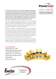
1. Design of a <strong>GAZ</strong> ® Ni-Cd pocket plate cell<br />
Gas drying or flame<br />
arresting vent<br />
Safety terminal<br />
Redundant leak<br />
protection minimizes<br />
carbonate formation.<br />
electrode edge<br />
Connected to pole bolt by<br />
screwing or welding.<br />
electrode frame<br />
Consisting of electrode<br />
edge and side bars. Seals the<br />
plates and works as a current<br />
collector.<br />
corrugated perforated plastic<br />
separator<br />
Insulates the plates and allows<br />
free circulation of electrolyte.<br />
horizontal pockets<br />
Formed by perforated<br />
steel strips containing<br />
the active material.<br />
Distance plate<br />
Prevents movement of the<br />
electrode pack.<br />
Publication No: <strong>EN</strong>-<strong>GAZ</strong>-<strong>TMSR</strong>-<strong>001</strong><br />
4
1.1 <strong>GAZ</strong> ® Venting System<br />
<strong>GAZ</strong> ® batteries can be equipped with a normal flip-top<br />
vent or optionally with a special gas drying as well as<br />
a flame arresting vent.<br />
Mode of action of <strong>GAZ</strong> ® gas drying<br />
or flame arresting vent<br />
The originated charging gases (hydrogen and oxygen),<br />
which occur during the charging process of<br />
Ni-Cd batteries, carry also small electrolyte drops of the<br />
electrolyte solution (aerosol). This leads to a quicker<br />
decline of the electrolyte level in comparison to the<br />
normal water decomposition during the overcharging<br />
and, thus, results in short maintenance intervals.<br />
Furthermore, a strong incrustation of the filling vents<br />
can be the result due to the creation of carbonate.<br />
By using the <strong>GAZ</strong> ® gas drying or flame arresting<br />
vents, this occurrence can be avoided. These vents<br />
containing small plastic particles on the large surface<br />
of which the electrolyte drops comprised are<br />
in the gas escaping from the cell are condensing to<br />
the greatest possible extent and, therefore, remain<br />
within the cells.<br />
Plastic<br />
particles<br />
Gas drying<br />
vent<br />
The additional feature of the <strong>GAZ</strong> ® flame-arresting<br />
vent is the microporous disc on the top which results<br />
in a diffused leakage of the charging gases. Moreover,<br />
high local concentrations can be prevented<br />
which finally leads to a lower risk of flammability.<br />
According to IEC 60623 the total amount of<br />
entrained potassium hydroxide shall be not more<br />
than 0.05 mg/ Ah during 2 hours overcharge. <strong>GAZ</strong> ®<br />
batteries with the special venting system improve the<br />
required value many times over to 0.011 mg/ Ah during<br />
2 hours overcharge.<br />
5<br />
1.2 <strong>GAZ</strong> ® Safety Terminal<br />
Use of the especially developed terminal design with<br />
redundant leak protection prevents any leakage of electrolyte.<br />
Depending on the cell range and type terminals<br />
are designed as female or male thread and polarity is<br />
colored marked.<br />
Internal & external sealing<br />
Redundant leak protection<br />
Publication No: <strong>EN</strong>-<strong>GAZ</strong>-<strong>TMSR</strong>-<strong>001</strong>
1.3 Electrode frame<br />
The electrode frame of <strong>GAZ</strong> ® Ni-Cd batteries consists of<br />
a right and a left side bar as well as the electrode edge,<br />
which are connected by welding shaping the electrode<br />
frame.<br />
The electrode frame operates as a current collector and<br />
also seals the electrode plates. This procedure leads<br />
to an electrode design with high mechanical robustness<br />
but also ensures a reliable service for the complete<br />
lifetime of the battery.<br />
1.4 Separators<br />
The separation of the electrodes is ensured by a corrugated<br />
perforated plastic (M- and L-types) or plastic grid<br />
separator (H-types). The plastic grid separator is used<br />
for high discharge types (H-types) in order to achieve<br />
a superior cell performance caused by a lower internal<br />
resistance, which is very typical and necessary for their<br />
high discharge currents.<br />
The separator also ensures a large space between the<br />
electrodes, which allows free circulation of the electrolyte<br />
and a good dissipation of the gases generated during<br />
end of charging.<br />
1.5 Positive and negative<br />
electrode plate<br />
The nickel-cadmium cell is composed of the positive plates<br />
containing nickel hydroxide and the negative plates containing<br />
cadmium hydroxide. The pockets formed from<br />
a nickel plated and perforated steel tape, the so-called<br />
pocket tape, infold strips of the active material.<br />
Pocket tape<br />
Active material<br />
The so originated electrode strips are mechanically<br />
linked together forming the electrode plate and are<br />
consecutively cut to size of the appropriate plate width<br />
based on the cell type and range.<br />
Publication No: <strong>EN</strong>-<strong>GAZ</strong>-<strong>TMSR</strong>-<strong>001</strong><br />
Electrode strip<br />
6<br />
The plates then are welded or mechanically linked to<br />
the plate frame (see point 3) forming the electrodes-<br />
the heart of the battery – and assembled to the plate<br />
block.<br />
Electrode strips<br />
Mechanically<br />
linked<br />
Electrode strips<br />
The basis for the extemely long useful lifetime and the<br />
very good cycle life features of the <strong>GAZ</strong> ® Ni-Cd pocket<br />
plate batteries are the special plate designs whose<br />
structural components are made of steel.<br />
This prevents the possibility of gradual deterioration by<br />
corrosion and since the alkaline electrolyte does not react<br />
with steel the substructure of the battery remains intact<br />
for the total lifetime of the battery. Very important<br />
and unique is the enfolding of the electrochemical active<br />
masses in the perforated nickel plated steel pockets, so<br />
that the risk of shedding or penetration of material is<br />
very small and consequently also the risk of structural<br />
damages and of soft short circuits is well under control.
1.6 Distance plate<br />
The distance plate operates as an additional stabilization<br />
to prevent any movement of the electrodes. It is<br />
an additional feature for applications where vibrations<br />
are possible.<br />
1.7 Cell cases<br />
The cell cases are made from a translucent polypropylene<br />
or polystyrene, which ensures a visual control<br />
of the electrolyte level. The exeptional sturdy <strong>GAZ</strong> ®<br />
cell cases provide a satisfactory service for the total<br />
lifetime of the battery but also will have a superior<br />
finish at every stage. The lid and the container are<br />
welded or glued together forming an integrative<br />
compound.<br />
All <strong>GAZ</strong> ® Ni-Cd cells have a single cell design that<br />
prevents in the greatest possible extent any leakage<br />
of the cell cases since they are made by injection<br />
molding out of one piece. Therefore, the weld or<br />
glueseams of the cell cases and the lids lies over the<br />
electrolyte level. The <strong>GAZ</strong> ® single cell design eliminates<br />
completely the risk of faulty welded seams on<br />
the sides and on the bottom of the cell cases. Caused<br />
by the single cell design an economical replacement<br />
of faulty cells is possible, where only the faulty cell<br />
can be replaced.<br />
A special flame retardent material (acc. to standard UL<br />
94 V0) is also available, which admittedly brings along<br />
some impaired properties. By using this material a visual<br />
check of the electrolyte is no longer possible.<br />
7<br />
1.8 Electrolyte<br />
The electrolyte used in <strong>GAZ</strong> ® Ni-Cd batteries is a solution<br />
of potassium hydroxide and lithium hydroxide<br />
that is optimized to give the best combination of performance,<br />
energy efficiency and a wide temperature<br />
range of use.<br />
The concentration of the standard electrolyte allows<br />
operations between – 30°C and + 50°C. For special<br />
operations within very low temperatures a special high<br />
density electrolyte can be used.<br />
It is an important property of the <strong>GAZ</strong> ® battery, and<br />
indeed of all nickel-cadmium batteries, that the electrolyte<br />
does not change during charge and discharge. It retains<br />
its ability to transfer ions between the cell plates,<br />
irrespective of the charge level.<br />
In most applications the electrolyte will retain its effectiveness<br />
for the life of the battery and will never need<br />
replacing. However, under certain conditions, such as<br />
extended use in high temperature situations, the electrolyte<br />
can become carbonated.<br />
If this occurs the battery performance can be improved<br />
by replacing the electrolyte (see „Maintenance<br />
and Handling Instructions“).<br />
400 KV INTERCONNECTION OF ABU DHABI ISLAND<br />
400/132/11kV GRID STATIONS E48 AND E19<br />
Publication No: <strong>EN</strong>-<strong>GAZ</strong>-<strong>TMSR</strong>-<strong>001</strong>
2. Battery range and applications<br />
2.1 Battery ranges<br />
In order to enable <strong>GAZ</strong> ® batteries to offer an appropriate<br />
solution in accordance with the customer’s requirements<br />
and to have a choice for any battery application<br />
existing on the market, <strong>GAZ</strong> ® Ni-Cd batteries are designed<br />
in four different performance ranges.<br />
KL …P<br />
This <strong>GAZ</strong> ® cell type has been especially designed for<br />
low rates of discharge over long periods, where the<br />
current is relatively low in comparison with the total<br />
stored energy. The discharges can generally be infrequent<br />
and the recommended discharge time for the<br />
KL …P range is 1 hour to 100 hours.<br />
KM …P TP<br />
The <strong>GAZ</strong> ® M-type battery has been especially designed<br />
for “mixed loads” that include a mixture of high and<br />
Cell type<br />
8<br />
l<br />
Low rate of<br />
discharge<br />
KL …P<br />
KL …<br />
M<br />
Medium rate<br />
of discharge<br />
KM …P<br />
KM …<br />
TP ...<br />
T ...<br />
M/n<br />
Medium rate<br />
of discharge<br />
KM ...P/N<br />
h<br />
High rate of<br />
discharge<br />
Intercity and urban transport X X X X<br />
Substations & signalling X X X X<br />
UPS X X X X<br />
Offshore & onshore oil & petrochemical refineries X X X X<br />
Emergency lighting X<br />
Telecommunication X X<br />
Photovoltaic X<br />
Diesel start X<br />
Ship equipment X X X X<br />
Electricity, gas & water production & distribution X X X X<br />
Emergency supply X X X<br />
Alarm equipment X<br />
Publication No: <strong>EN</strong>-<strong>GAZ</strong>-<strong>TMSR</strong>-<strong>001</strong><br />
low rates of discharge. It is used for frequent and infrequent<br />
discharges and the recommended discharge<br />
time is 30 min to 120 min.<br />
KM …P/N NON-STOP<br />
This <strong>GAZ</strong> ® cell type is a further developed M-type,<br />
which because of a special perforation higher discharge<br />
currents for special applications up to 1 hour.<br />
It is especially used for UPS and similar applications<br />
and the recommended discharge time is 10 min to<br />
60 min.<br />
KH …P TSP<br />
The <strong>GAZ</strong> ® H-type battery was designed for high current<br />
discharging over short discharge periods. The<br />
recommended discharge time for this cell range is 1<br />
s to 30 min.<br />
KH ...P<br />
KH ...<br />
TSP ...<br />
TS ...
2.2 Applications and<br />
choice of cell type<br />
<strong>GAZ</strong> ® Ni-Cd batteries cover a wide range of applications<br />
and are used in almost every sector, no matter if it is a<br />
private, industrial, commercial, governmental or military<br />
one. The table on page 8 on which some examples can<br />
be found represents only a small overview in the extended<br />
field of applications. Therefore, it is to be understood<br />
as general information.<br />
3. Electrochemistry of<br />
Ni-Cd batteries<br />
Oxidation of cadmium at the negative electrode<br />
Cd Cd 2+ + 2 e¯<br />
Reduction of trivalent nickel ions to bivalent at the positive<br />
electrode<br />
Ni 3+ + e¯ Ni 2+<br />
During charging the both reactions are reversed.<br />
The complete reaction is:<br />
negative electrode<br />
Cd + 2 OH¯ Cd(OH) 2 + 2 e¯<br />
positive electrode<br />
2 NiOOH + 2 H 2 O + 2 e¯ 2 Ni(OH) 2 + 2 OH¯<br />
cell reaction<br />
4. 2 NiOOH Operating + Cd + 2 features H O 2 Ni(OH) + Cd(OH) 2 2 2<br />
9<br />
4. Operating features<br />
4.1 Capacity<br />
The capacity of nickel-cadmium batteries is rated in ampere-hours<br />
(Ah) and is the quantity of electricity at +20°C<br />
(± 5°C) which can supply for a 5 hour discharge after being<br />
fully charged for 7.5 hours at 0.2 C 5 . These figures<br />
and procedures are based on the IEC 60623 standard.<br />
According to IEC 60623, 0.2 C 5 A is also expressed as<br />
0.2 I t A. The reference test current It is expressed as:<br />
C n<br />
n<br />
I t A=<br />
C Ah n<br />
1 h<br />
is the rated capacity declared by the<br />
manufacturer in ampere-hours (Ah)<br />
is the time based in hours (h) for which<br />
the rated capacity is declared<br />
4.2 Cell voltage<br />
The cell voltage of a Ni-Cd cell is the result of the electrochemical<br />
potentials of the nickel and the cadmium active<br />
materials in cooperation of the potassium hydroxide<br />
electrolyte. Therefore, the nominal voltage for this electrochemical<br />
couple is 1.2 V. From the electrochemistry of<br />
the reaction given above (see point 3), the free voltage<br />
of 1.3 V is given for the Ni-Cd cell. This voltage is also<br />
observed directly after charging of the cell.<br />
4.3 Internal resistance<br />
The internal resistance of a Ni-Cd cell is very difficult<br />
to measure and to define since it varies with different<br />
temperature and state of discharge. The internal<br />
resistance also depends on the cell type and size<br />
as it increases for lower state of charge. Apart from<br />
this the internal resistance of a fully discharged cell<br />
carries no weight. Reducing the temperature also<br />
increases the internal resistance. The correct values<br />
regarding the special conditions can be provided by<br />
our technical staff.<br />
Publication No: <strong>EN</strong>-<strong>GAZ</strong>-<strong>TMSR</strong>-<strong>001</strong>
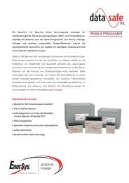
4.4 Impact of temperature on cell performance and available capacity<br />
When sizing and choosing a battery the variations in<br />
ambient temperature and their influence on the cell<br />
performance have to be taken into consideration.<br />
Low ambient temperature conditions reduce the cell<br />
performance, but on the other hand operations with<br />
% of rated capacity at 25°C<br />
120<br />
100<br />
80<br />
60<br />
40<br />
20<br />
0<br />
Publication No: <strong>EN</strong>-<strong>GAZ</strong>-<strong>TMSR</strong>-<strong>001</strong><br />
10<br />
higher temperatures are similar to those at normal temperatures.<br />
The effect of low temperatures is increasing<br />
with higher rates of discharge.<br />
The values, which have to be taken into account, can<br />
be found in the following graph.<br />
TM<br />
Typical <strong>GAZ</strong> ® NiCd-cell performance variation with temperature<br />
-40 -35 -30 -25 -20 -15 -10 -5 0 5 10 15 20 25 30<br />
Temperature in °C<br />
5-hour discharge rate
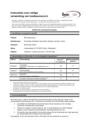
4.5 Impact of temperature on lifetime<br />
As with every battery system an increased temperature<br />
always reduces the expected service lifetime<br />
and although the <strong>GAZ</strong> ® Ni-Cd battery is designed to<br />
reach a lifetime of over 20 years this is also the case.<br />
The following graph is included to demonstrate that<br />
the reduction in lifetime of a <strong>GAZ</strong> ® Ni-Cd battery<br />
Percentage of +25°C lifetime [%]<br />
100<br />
90<br />
80<br />
70<br />
60<br />
50<br />
40<br />
30<br />
20<br />
10<br />
0<br />
4.6 Short-circuit values<br />
The short-circuit values of a <strong>GAZ</strong> ® Ni-Cd pocket plate<br />
battery depend on and vary from cell range to cell<br />
range. The special values can be provided by our technical<br />
staff on request.<br />
11<br />
is many times lower than for a lead acid battery.<br />
For Ni-Cd batteries the normal operating temperature<br />
is based at + 20°C (± 5°C) and, therefore, special<br />
considerations have to be taken into account<br />
when dimensioning a Ni-Cd battery for high temperature<br />
applications.<br />
Lifetime of batteries at higher temperatures as percentage of +25°C lifetime<br />
Ni-Cd batteries<br />
Lead acid batteries<br />
25 30 35 40<br />
Temperature in °C<br />
45 50 55<br />
Publication No: <strong>EN</strong>-<strong>GAZ</strong>-<strong>TMSR</strong>-<strong>001</strong>
4.7 Open circuit loss<br />
The state of charge of a cell on open circuit slowly decreases<br />
due to its self-discharge. This decrease is quite<br />
rapid during the first two weeks and then stabilizes at<br />
about 2% per month at + 20°C. In general the self-<br />
Loss of capacity [%]<br />
4.8 Cycling<br />
The <strong>GAZ</strong> ® Ni-Cd battery is designed to obtain a<br />
huge number of cycles in stationary standby operations.<br />
The important fact and basis for the number of<br />
cycles the battery is able to provide is the depth of<br />
discharge. The less deeply a battery is discharged the<br />
Charge-discharge cycles<br />
60<br />
50<br />
40<br />
30<br />
20<br />
10<br />
0<br />
8000<br />
7000<br />
6000<br />
5000<br />
4000<br />
3000<br />
2000<br />
1000<br />
0<br />
Publication No: <strong>EN</strong>-<strong>GAZ</strong>-<strong>TMSR</strong>-<strong>001</strong><br />
TM<br />
Self discharge of <strong>GAZ</strong> ® NiCd-accumulators (fully charged)<br />
Months<br />
12<br />
discharge of a <strong>GAZ</strong> ® Ni-Cd battery is affected by various<br />
temperatures. The open circuit loss is reduced at low<br />
temperatures, while the self-discharge is significantly<br />
increased at higher temperatures.<br />
40°C<br />
20°C<br />
0°C<br />
0 1.0 2.0 3.0 4.0 5.0 6.0 7.0 8.0 9.0 10.0 11.0 12.0<br />
greater the number of cycles it is capable to provide<br />
before being unable to achieve the minimum design<br />
limit. On the graph below typical values for the effect<br />
of depth of discharge on the available cycle life can<br />
be found.<br />
Cycle life versus depth of discharge expressed as a percentage of the rated capacity (20°C)<br />
15 20 25 30 35 40 45 50 55 60 65 70 75 80 85 90 95 100<br />
Depth of discharge [&]
4.9 Water consumption and gas evolution<br />
At the final stage of the charging procedure of a<br />
<strong>GAZ</strong> ® Ni-Cd battery the provided electrical energy<br />
cannot be fully absorbed but is absolutely necessary<br />
to reach the fully charged state of the cells. The<br />
difference between absorbed and provided energy<br />
leads to a break down of the electrolyte’s water content<br />
into oxygen and hydrogen (electrolysis). This loss<br />
has to be compensated by topping up the cells with<br />
pure distilled water.<br />
The water loss depends on the current used for overcharging.<br />
A battery on stand by operation will consume<br />
less water than a battery that is cycled constantly,<br />
i.e. which is charged and discharged on a<br />
regular basis.<br />
In theory, the quantity of water used can be found by<br />
Faraday’s equation that each ampere hour of overcharge<br />
breaks down 0.336 cm 3 of water.<br />
However, in practice, the water usage will be less<br />
than this, as the overcharge current is also needed to<br />
counteract self-discharge of the electrodes.<br />
The overcharge current is a function of both voltage<br />
and temperature, so both have an influence on the<br />
consumption of water. The table below gives typical<br />
water consumption values over a range of voltages.<br />
Loss of water [cm²/month and Ah]<br />
2.5<br />
2<br />
1.5<br />
1<br />
0.5<br />
Charging voltage [V/cell]<br />
13<br />
Example:<br />
A cell KM 110 P is floated at 1.41 V/cell<br />
The electrolyte reserve for this cell is approx. 400 cm³<br />
From the table below a <strong>GAZ</strong> ® cell at 1.41 V per cell<br />
will use 0.25 cm³/month for 1 Ah of capacity<br />
That means a KM 110 P will use<br />
0.25 cm³/month x 110 Ah = 27.5 cm³/month<br />
and the electrolyte reserve will be used in<br />
400 cm³ / 27.5 cm³/month = 14.5 months<br />
The gas evolution is a function of the amount of water<br />
electrolyzed into hydrogen and oxygen and is predominantly<br />
given off at the end of the charging period. The<br />
battery does not give off any gas during a normal discharge.<br />
During electrolysis the amount of 1Ah produces<br />
684 cm³ of gas mixture and this gas mixture is in the<br />
proportion of 2/3 hydrogen and 1/3 oxygen. Thus 1Ah<br />
produces about 456 cm³ of hydrogen.<br />
Loss of water for <strong>GAZ</strong> ® cells and different charging voltages (app.) 20 ° C<br />
0<br />
1.40 1.41 1.42 1.43 1.44 1.45 1.46 1.47 1.48 1.49 1.50 1.51 1.52 1.53 1.54 1.55<br />
Publication No: <strong>EN</strong>-<strong>GAZ</strong>-<strong>TMSR</strong>-<strong>001</strong>
5. Principles and methods of<br />
sizing of <strong>GAZ</strong> ® Ni-Cd-batteries<br />
for standby applications.<br />
All <strong>GAZ</strong> ® Ni-Cd batteries used for standby floating applications<br />
are sized according to the international sizing<br />
method IEEE 1115. We have developed a special calculation<br />
program which is available over the Internet and<br />
allows us to update it regularly without bothering our<br />
customers. It provides the possibility to calculate with<br />
multiple discharges, and to include the temperature derating<br />
factor as well as the ageing factor of the battery.<br />
A significant feature and advantage of the <strong>GAZ</strong> ® Ni-Cd<br />
battery in comparison to the lead acid battery is that it<br />
can be fully discharged without any inconvenience to the<br />
lifetime or recharge of the battery. Further, it is an advantage<br />
to discharge the battery to the lowest practical value<br />
to extract the maximum energy the battery is able to<br />
provide in order to find out the most beneficial solution.<br />
The most important sizing parameters are:<br />
5.1 Voltage window<br />
This is the minimum and maximum voltage acceptable<br />
for the system. The maximum voltage provides the voltage<br />
that is available to charge the battery, whereas, the<br />
minimum voltage gives the lowest voltage acceptable<br />
to the system to that the battery can be discharged.<br />
5.2 Load profile<br />
The load profile is the electrical performance required<br />
by the system from the battery for the particular application.<br />
It can be expressed in terms of amperes for<br />
certain duration or in watts for certain duration. The<br />
requirements might vary for example from just one discharge<br />
to multiple discharges of a complex nature. In<br />
order to calculate the appropriated battery size please<br />
take into consideration point 5.1 voltage window.<br />
5.3 Ambient temperature<br />
The ambient temperature will have in any case an influence<br />
on the sizing of the battery (see point 4.4 Impact<br />
of temperature on cell performance and 4.5 Impact of<br />
temperature on lifetime).<br />
Publication No: <strong>EN</strong>-<strong>GAZ</strong>-<strong>TMSR</strong>-<strong>001</strong><br />
14<br />
5.4 Recharge time<br />
and state of charge<br />
Some applications might require a full discharge cycle<br />
of the battery after a certain time after the previous<br />
discharge. The factors to be taken into account depend<br />
on the depth of discharge, the rate of discharge as well<br />
as the charging conditions.<br />
5.5 Ageing<br />
It might be required that a value has to be added to ensure<br />
the correct service of the battery during the lifetime.<br />
The value to be used depends on the discharge rate of<br />
the battery and on the conditions under which is carried<br />
out. Our experts or partners are able to help you choose<br />
the right battery for your special requirements.<br />
computed values according to IEEE Std 1115-2000<br />
capacity temperature<br />
change duration time to end rating derating required<br />
load in load of period of section factor at factor for section<br />
period (amperes) (amperes) (minutes)<br />
section 1<br />
(minutes) t Min Rate (Kt) t Min (Tt) (rated amp hrs)<br />
1 100.00 100.00 600 600 9.8590 1.1351 1119.0692<br />
section 1 total: 1119.0692<br />
range: KL 150-1700 P design margin factor: 1.10<br />
endvoltage per cell: 1.05 Vpc aging factor: 1.25<br />
temperature: 5°C to 50°C<br />
max section size: 1119.07 Ah<br />
use floating derating factor: 1.00 (use: Yes)<br />
Your data was saved successfully.<br />
Please contact <strong>GAZ</strong> with order number 002062.<br />
computed cellsize: 1538.72 Ah<br />
use the cell: KL 1620 P<br />
user: Peko<br />
order number: 002062<br />
2008-09-30 15:36:02<br />
date:
5.6 Floating effect - Voltage depression<br />
When a <strong>GAZ</strong> ® Ni-Cd battery operates at a fixed floating<br />
voltage over a certain period of time, a decrease<br />
in the voltage level of the discharge curve occurs. It<br />
begins after one week and reaches its peak in approximately<br />
3 months. Since this effect reduces the<br />
voltage level of the battery it can be considered as<br />
reducing the performance and autonomy of the battery<br />
too. Therefore, it is necessary to take this effect<br />
into consideration when sizing a <strong>GAZ</strong> ® Ni-Cd battery.<br />
The <strong>GAZ</strong> ® calculation program gives the possibility to<br />
Floating derating factor<br />
1.10<br />
1.00<br />
0.90<br />
0.80<br />
0.70<br />
0.60<br />
0.50<br />
0.40<br />
0.30<br />
6. Charging<br />
The <strong>GAZ</strong> ® Ni-Cd battery can generally be charged by<br />
all normal methods. Usually, batteries in parallel operation<br />
with charger and load are charged with constant<br />
voltage. For operations where the battery is charged<br />
separately from the load, charging with constant current<br />
is possible. Overcharging will not damage the battery<br />
but will lead to an increase of water consumption.<br />
6.1 Constant voltage charge<br />
The common method to charge a battery in stationary<br />
applications is carried out by a constant voltage system<br />
and the recommended solution is to use a two-rate type<br />
that is able to provide a constant voltage charge and<br />
a lower floating voltage or single rate floating voltage.<br />
The two level charger has an high voltage stage to<br />
charge the battery properly after a discharge followed<br />
15<br />
include this factor into the customers´calculation.<br />
Floating derating factor in accordance of discharge time<br />
Floating derating factor for KM-types<br />
to an end voltage of 1.10 V/cell<br />
1 5 30 60 5 10 15 20 30 1 1.5 2 3 5<br />
Time [sec] Time [min] Time [hours]<br />
The floating effect is a reversible effect and can only<br />
be eliminated by a full discharge/ charge cycle. Please<br />
note that it cannot be prevented by just a boost<br />
charge. The <strong>GAZ</strong> ® battery sizing program provides<br />
the option to calculate with and without this floating<br />
effect so that the customer is able to see the added<br />
values. Our recommendation is always to include this<br />
factor when sizing a battery.<br />
by a lower voltage float level charge. This results in a<br />
quick charge of the battery and in relatively low water<br />
consumption due to the low level float charge.<br />
Two level charge<br />
Boost charge: 1.55 – 1.70 V/cell<br />
Floating 1.40 – 1.42 V/cell<br />
A high voltage will increase the speed and efficiency of<br />
recharging the battery.<br />
In reality often single level charger can be found. This is<br />
surely a compromise between a voltage high enough to<br />
charge the battery and low enough to have adequate<br />
water consumption.<br />
Single level charge<br />
1.45 – 1.50 V/cell<br />
Example:<br />
You can discharge the cell<br />
KM 110 P for 30 minutes with a<br />
current of 91 Ampere to 1.10 V<br />
according discharge table.<br />
This value is valid after fully constant<br />
current charging.<br />
If you charge the cell at float<br />
charging you have to reduce the<br />
discharge time with factor 0.74.<br />
That means the discharge time<br />
is 22.2 minutes only.<br />
This fact will be considered<br />
by the <strong>GAZ</strong> ® battery calculation<br />
program automatically if<br />
this option is chosen.<br />
For commissioning the batteries please see point 7.3.5.<br />
Publication No: <strong>EN</strong>-<strong>GAZ</strong>-<strong>TMSR</strong>-<strong>001</strong>
6.2 Charge acceptance<br />
A discharged <strong>GAZ</strong> ® Ni-Cd cell will take its time to<br />
reach a full state of charge. On the tables below the<br />
Voltage per cell [V]<br />
Voltage per cell [V]<br />
1.7<br />
1.65<br />
1.6<br />
1.55<br />
1.5<br />
1.45<br />
1.4<br />
1.7<br />
1.65<br />
1.6<br />
1.55<br />
1.5<br />
1.45<br />
Publication No: <strong>EN</strong>-<strong>GAZ</strong>-<strong>TMSR</strong>-<strong>001</strong><br />
Charging time [hours]<br />
16<br />
time needed to achieve a certain stage of charge can<br />
be found.<br />
Time to reach state of charge at charging voltages for fully discharged <strong>GAZ</strong> ® Ni-Cd cells<br />
(M-Range: current Limit 0.2 C 5 A)<br />
85% CHARGED<br />
80% CHARGED<br />
75% CHARGED<br />
90% CHARGED<br />
95% CHARGED<br />
FULLY CHARGED<br />
1 2 3 4 5 6 7 8 9 10 20 30 40 50 100 200 300 400 500 1000<br />
Time to reach state of charge at charging voltages for fully discharged <strong>GAZ</strong> ® Ni-Cd cells<br />
(L-Range: current Limit 0.2 C 5 A)<br />
85% CHARGED<br />
80% CHARGED<br />
75% CHARGED<br />
1.4<br />
1 2 3 4 5 6 7 8 9 10<br />
Charging time [hours]<br />
FULLY CHARGED<br />
95% CHARGED<br />
90% CHARGED<br />
20 30 40 50 100 200 300 400 500 1000
Voltage per cell [V]<br />
1.7<br />
1.65<br />
1.6<br />
1.55<br />
1.5<br />
1.45<br />
1.4<br />
Time to reach state of charge at charging voltages for fully discharged <strong>GAZ</strong> ® Ni-Cd cells<br />
(H-Range: current Limit 0.2 C 5 A)<br />
85% CHARGED<br />
80% CHARGED<br />
75% CHARGED<br />
1 2 3 4 5 6 7 8 9 10<br />
6.3 Charge efficiency<br />
The charge efficiency depends mostly on the state of<br />
charge of the battery and the ambient temperature<br />
as well as the charging current. For much of its charge<br />
profile the <strong>GAZ</strong> ® Ni-Cd battery is charged at a high<br />
level of efficiency. But if the battery approaches a fully<br />
charged condition the charging efficiency decreases.<br />
Charging time [hours]<br />
17<br />
FULLY CHARGED<br />
95% CHARGED<br />
90% CHARGED<br />
20 30 40 50 100 200 300 400 500 1000<br />
Publication No: <strong>EN</strong>-<strong>GAZ</strong>-<strong>TMSR</strong>-<strong>001</strong>
6.4 Temperature influence<br />
The electrochemical behaviour of the battery becomes<br />
more active if temperature increases, i.e. for the same<br />
floating voltage the current increases. If the temperature<br />
decreases the reverse occurs. Increasing the current increases<br />
the consumption of water and reducing the current<br />
could lead to an insufficient charging.<br />
For standby application it is normally not necessary to<br />
compensate the charging voltage with the temperature.<br />
In order to reduce the water consumption it is recom-<br />
Float Voltage [V/cell]<br />
1.56<br />
1.54<br />
1.52<br />
1.50<br />
1.48<br />
1.46<br />
1.44<br />
1.42<br />
1.40<br />
1.38<br />
1.36<br />
1.34<br />
1.32<br />
1.30<br />
6.5 Commissioning<br />
A good first charge is essential to prepare the battery<br />
for its long service lifetime. Above all it is important<br />
for discharged cells since they are in a totally discharged<br />
stage (see point 7.3.5 Commissioning)<br />
Publication No: <strong>EN</strong>-<strong>GAZ</strong>-<strong>TMSR</strong>-<strong>001</strong><br />
Float Voltage with Temperature Correction<br />
18<br />
mended to compensate it at elevated temperature as for<br />
example from + 35°C on by use of the negative temperature<br />
coefficient of −3mV/K.<br />
For operation at low temperatures, i.e. below 0°C,<br />
there is a risk of poor charging and it is recommended<br />
to adjust the charging voltage or to compensate<br />
the charging with the temperature (- 3 mV/K, starting<br />
from an ambient temperature of + 20°C).<br />
U-Float<br />
-25 -20 -15 -10 -5 0 5 10 15 20 25 30 35 40 45 50 55 60<br />
Temperature in °C
7. Installation and<br />
operating instructions<br />
7.1. Receiving the battery<br />
The cells are not to be stored in packaging, therefore,<br />
unpack the battery immediately after arrival. Do not<br />
overturn the package. The battery cells are equipped<br />
with a blue plastic transport plug. The battery can be<br />
delivered<br />
- Filled and charged – the battery is ready for installation.<br />
Replace the transport plug by the vent<br />
cap included in our accessories only before use<br />
- Filled and discharged – replace the transport<br />
plug by the vent cap included in our accessories<br />
only before use<br />
- Unfilled and discharged – do not remove the<br />
transport plug until ready to fill the battery<br />
The battery must not be charged with the transport<br />
plug in the cells as this can damage the battery.<br />
7.2. Storage<br />
The rooms provided for storing the batteries must be<br />
clean, dry, cool (+10°C to 30°C - in compliance with<br />
IEC 60623) and well ventilated. The cells are not to<br />
be stored in closed packaging and must not be exposed<br />
to direct sunlight or UV-radiation.<br />
If the cells are delivered in plywood boxes, open<br />
the boxes before storage and remove the packing<br />
material on the top of the cells. If the cells<br />
are delivered on pallets, remove the packing<br />
material on the top of the cells.<br />
7.2.1 Uncharged and unfilled cells<br />
Provided the correct storage conditions are met then<br />
the cells and batteries can be stored for long periods<br />
without damage if they are deeply discharged,<br />
drained and well sealed. It is very important that the<br />
cells are sealed with the plastic transport plug tightly<br />
in place. It is necessary to check after receipt and at<br />
least every year. Leaky plugs allow the carbon dioxide<br />
from the atmosphere to infiltrate the cell, which will<br />
result in carbonation of the plates. That may impair<br />
the capacity of the battery.<br />
19<br />
7.2.2 Charged and filled cells/<br />
discharged and filled cells<br />
Filled cells can be stored 12 months at the most from<br />
the time of delivery.<br />
Storage of filled cells at a temperature above +30°C<br />
results in loss of capacity. This can be approximately<br />
5% per 10 degrees/year when the temperature exceeds<br />
+30°C. It is very important that the cells are<br />
sealed with the plastic transport plugs tightly in place.<br />
This is to check after receipt of goods. In case of loss<br />
of electrolyte during transport, refill the cell until the<br />
“MIN” mark with electrolyte before storage.<br />
7.3. Installation<br />
<strong>EN</strong> 50272-2:2<strong>001</strong> “Accumulators and battery installations,<br />
stationary battery installations” is binding for<br />
the setting up and operation of battery installations.<br />
For non stationary installations specific standards are<br />
valid.<br />
7.3.1 Location<br />
Install the battery in a dry and clean room. Avoid<br />
in any case direct sunlight and heat. The battery<br />
will give the optimal performance and maximum<br />
service life if the ambient temperature lies<br />
between + 10°C and + 30°C.<br />
7.3.2 Ventilation<br />
During the last part of charging the battery gases<br />
(oxygen and hydrogen mixture) are emitted. At normal<br />
float charge the gas evolution is very small but<br />
some ventilation is necessary.<br />
Special regulations for ventilation might be required<br />
in your area for certain applications. If no regulations<br />
are fixed in your area DIN <strong>EN</strong> 50272 – 2: 2<strong>001</strong> should<br />
be met.<br />
Publication No: <strong>EN</strong>-<strong>GAZ</strong>-<strong>TMSR</strong>-<strong>001</strong>
�<br />
�<br />
�<br />
�<br />
�<br />
�<br />
�<br />
�<br />
�<br />
�<br />
7.3.3 Setting up<br />
Always pay attention to the assembly drawings, circuit<br />
diagrams and other separate instructions. The transport<br />
plugs have to be replaced by the vent caps included<br />
in the accessories. If batteries are supplied “filled and<br />
charged”, the electrolyte level should be checked, and if<br />
necessary, topped off as described in point 3.4.<br />
Cell connectors and/or flexible cables should be checked<br />
to ensure they are tightly seated. Terminal nuts, screws<br />
and connectors must be tightly seated. If necessary<br />
tighten with a torque spanner.<br />
Torque loading for:<br />
M10: 8 Nm<br />
M16: 20 Nm<br />
M20: 25 Nm<br />
Female thread:<br />
M 8: 20 – 25 Nm<br />
M10: 25 – 30 Nm<br />
The connectors and terminals should be corrosion-protected<br />
by coating with thin layer of anti corrosion grease.<br />
nut connection<br />
1) cell container<br />
2) cell connector<br />
3) spring washer<br />
4) nut<br />
5) connector cover<br />
screw connection<br />
1) cell container<br />
2) cell connector<br />
3) spring washer<br />
4) screw<br />
5) connector cover<br />
Publication No: <strong>EN</strong>-<strong>GAZ</strong>-<strong>TMSR</strong>-<strong>001</strong><br />
�<br />
�<br />
�<br />
�<br />
�<br />
�<br />
�<br />
�<br />
�<br />
�<br />
20<br />
7.3.4 Electrolyte<br />
The electrolyte for <strong>GAZ</strong> ® Ni-Cd batteries consists of diluted<br />
caustic potash solution (specific gravity 1.20 kg/litre<br />
± 0.01 kg/litre) with a lithium hydroxide component, in<br />
accordance with IEC 60993. The caustic potash solution is<br />
prepared in accordance with factory regulations. The specific<br />
gravity of the electrolyte does not allow any conclusion<br />
to be drawn on the charging state of the battery. It<br />
changes only insignificantly during charging and discharging<br />
and is only minimally related to the temperature.<br />
- Battery delivered unfilled and dischargedif<br />
the electrolyte is supplied dry, it is to be mixed according<br />
to the enclosed mixing instruction. Remove<br />
the transport plugs from the cell just before filling.<br />
Fill the cells up to 20 mm above the lower level mark<br />
“MIN”. Steel cased cells have to be filled up to the<br />
top edge of the plates. When using battery racks fill<br />
cells before putting up. Only use genuine electrolyte.<br />
- Battery delivered filled and charged or dischargedcheck<br />
electrolyte level. It should not be less than 20 mm<br />
below the upper level mark “MAX” see 5.2.<br />
- “Only use genuine electrolyte supplied by <strong>GAZ</strong> ® “.<br />
7.3.5 Commissioning<br />
A good commissioning is very important. The following<br />
instructions are valid for commissioning at 20°C<br />
till 30°C. For different conditions please contact<br />
manufacturer. Charge at constant current is preferable.<br />
If a site test is requested it has to be carried out<br />
in accordance with to IEC 60623.<br />
According to IEC 60623, 0.2 C 5 A is also expressed<br />
as 0.2 I t A.<br />
The reference test current It is expressed as:<br />
C Ah n<br />
I A= t<br />
1 h<br />
Example:<br />
0.2 I t A means 20 A for a 100 Ah battery or<br />
100 A for a 500 Ah battery<br />
7.3.5.1 Commissioning with<br />
constant current<br />
Battery delivered unfilled and discharged – after a<br />
period of 5 hours from filling the electrolyte in the battery<br />
should be charged for 15 hours at the rated charging<br />
current 0.2 I t A. Approximately 4 hours after the end<br />
of charging the electrolyte level should be adjusted to
the upper electrolyte level marking “MAX” by using<br />
only genuine electrolyte. For cells with steel cases the<br />
electrolyte level should be adjusted to the maximum<br />
level according to the “Instruction for the control of<br />
electrolyte level”. During the charge the electrolyte<br />
level and temperature should be observed, see<br />
point 7.5.4. The electrolyte level should never fall<br />
below the “MIN” mark.<br />
Battery delivered filled and discharged-the battery<br />
should be charged for 15 hours at the rated charging<br />
current 0.2 I t A. Approximately 4 hours after the end of<br />
charging the electrolyte level should be adjusted to the<br />
upper electrolyte level marking “MAX” by using distilled<br />
or deionized water in accordance with IEC 60993.<br />
For cells with steel cases the electrolyte level should be<br />
adjusted to the maximum level according to the “Instruction<br />
for the control of electrolyte level”. During<br />
the charge the electrolyte level and temperature<br />
should be observed, see point 7.5.4. The electrolyte<br />
level should never fall below the “MIN” mark.<br />
Battery delivered filled and charged and stored for<br />
more than 12 months-the battery should be charged<br />
for 15 hours at the rated charging current 0.2 I t A. Approximately<br />
4 hours after the end of charging the electrolyte<br />
level should be adjusted to the upper electrolyte<br />
level marking “MAX” by using distilled or deionized<br />
water in accordance with IEC 60993. For cells with<br />
steel cases the electrolyte level should be adjusted to<br />
the maximum level according to the “Instruction for the<br />
control of electrolyte level”. During the charge the<br />
electrolyte level and temperature should be observed<br />
see point 7.5.4. The electrolyte level should<br />
never fall below the “MIN” mark.<br />
Battery delivered filled and charged-a 5 hours<br />
charge at the rated charging current 0.2 I t A must be<br />
carried out before putting the battery into operation.<br />
Approximately 4 hours after the end of charging the<br />
electrolyte level should be adjusted to the upper electrolyte<br />
level marking “MAX” by using distilled or deionized<br />
water in accordance with IEC 60993. For cells with<br />
steel cases the electrolyte level should be adjusted to<br />
the maximum level according to the “Instruction for<br />
the control of electrolyte level”. During the charge<br />
the electrolyte level and temperature should be<br />
observed, see point 7.5.4. The electrolyte level<br />
should never fall below the “MIN” mark.<br />
7.3.5.2 Commissioning with<br />
constant voltage<br />
If the charger´s maximum voltage setting is too low to<br />
supply constant current charging divide the battery into<br />
two parts to be charged individually.<br />
21<br />
Battery delivered unfilled and discharged-after a<br />
period of 5 hours from filling the electrolyte in the battery<br />
should be charged for 30 hours at the rated charging<br />
voltage of 1.65 V/cell. The current limit should be 0.2 I t A<br />
maximum. Approximately 4 hours after the end of charging<br />
the electrolyte level should be adjusted to the upper<br />
electrolyte level marking “MAX” by using only genuine<br />
electrolyte. For cells with steel cases the electrolyte level<br />
should be adjusted to the maximum level according to<br />
the “Instruction for the control of electrolyte level”. During<br />
the charge the electrolyte level and temperature<br />
should be observed, see point 7.5.4. The electrolyte<br />
level should never fall below the “MIN” mark.<br />
Battery delivered filled and discharged-the battery<br />
should be charged for 30 hours at the rated charging<br />
voltage of 1.65 V/cell. The current limit should be<br />
0.2 I t A maximum. Approximately 4 hours after the end<br />
of charging the electrolyte level should be adjusted<br />
to the upper electrolyte level marking “MAX” by using<br />
distilled or deionized water in accordance with IEC<br />
60993. For cells with steel cases the electrolyte level<br />
should be adjusted to the maximum level according<br />
to the “Instruction for the control of electrolyte level”.<br />
During the charge the electrolyte level and temperature<br />
should be observed, see point 7.5.4. The electrolyte<br />
level should never fall below the “MIN” mark.<br />
Battery delivered filled and charged and stored for<br />
more than 12 months-the battery should be charged for<br />
30 hours at the rated charging voltage of 1.65 V/cell. The<br />
current limit should be 0.2 I t A maximum. Approximately<br />
4 hours after the end of charging the electrolyte level<br />
should be adjusted to the upper electrolyte level marking<br />
“MAX” by using distilled or deionized water in accordance<br />
with IEC 60993. For cells with steel cases the<br />
electrolyte level should be adjusted to the maximum level<br />
according to the “Instruction for the control of electrolyte<br />
level”. During the charge the electrolyte level and<br />
temperature should be observed, see point 7.5.4.<br />
The electrolyte level should never fall below the<br />
“MIN” mark.<br />
Battery delivered filled and charged-/a 10 hours<br />
charge at the rated charging voltage of 1.65 V/cell must<br />
be carried out before putting the battery into operation.<br />
The current limit should be 0.2 I t A maximum. Approximately<br />
4 hours after the end of charging the electrolyte<br />
level should be adjusted to the upper electrolyte level<br />
marking “MAX” by using distilled or deionized water<br />
in accordance with IEC 60993. For cells with steel<br />
cases the electrolyte level should be adjusted to the<br />
maximum level according to the “Instruction for the<br />
control of electrolyte level”. During the charge the<br />
electrolyte level and temperature should be<br />
observed, see point 7.5.4. The electrolyte level<br />
should never fall below the “MIN” mark.<br />
Publication No: <strong>EN</strong>-<strong>GAZ</strong>-<strong>TMSR</strong>-<strong>001</strong>
7.4. Charging in operation<br />
7.4.1 Continuous battery<br />
power supply<br />
(with occasional battery discharge)<br />
Recommended charging voltage for ambient temperatures<br />
+ 20°C to + 25°C<br />
Do not remove the vent caps during float-, boost<br />
charge and buffer operation. The current limit should<br />
be 0.3 I t A maximum in general.<br />
7.4.1.1 Two level charge<br />
Floating 1.40 – 1.42 V/cell<br />
Boost charge: 1.55 – 1.70 V/cell<br />
A high voltage will increase the speed and efficiency<br />
of recharging the battery.<br />
7.4.1.2 Single level charge<br />
1.45 – 1.50 V/cell<br />
7.4.2 Buffer operation<br />
Where the load exceeds the charger rating.<br />
1.45 – 1.55 V/cell<br />
7.5. Periodic Maintenance<br />
The battery must be kept clean using only water. Do<br />
not use a wire brush or solvents of any kind. Vent<br />
caps can be rinsed in clean warm water if necessary<br />
but must be dried before using them again.<br />
Check regularly (approx. every 6 months) that all connectors,<br />
nuts and screws are tightly fastened. Defective<br />
vent caps and seals should be replaced. All metal<br />
parts of the battery should be corrosion-protected by<br />
coating with a thin layer of anti-corrosion grease. Do<br />
not coat any plastic part of the battery, for example<br />
cell cases!<br />
Publication No: <strong>EN</strong>-<strong>GAZ</strong>-<strong>TMSR</strong>-<strong>001</strong><br />
22<br />
Check the charging voltage. If a battery is connected<br />
in parallel it is important that the recommended<br />
charging voltage remains unchanged. The charging<br />
current in the strings should also be checked to ensure<br />
it is equal. These checks have to be carried out<br />
once a year. High water consumption of the battery<br />
is usually caused by improper voltage setting of the<br />
charger.<br />
7.5.1 Equalising charge<br />
It is recommended to carry out an equalising<br />
charge once a year to maintain capacity and to stabilise<br />
the voltage levels of the cells. The equalising<br />
charge can be carried out for 15 hours at 0.2 I t A or<br />
with the boost charging stage in conformity with<br />
the characteristic curve of the available charging<br />
implement. The electrolyte level is to be checked<br />
after an equalising charge.<br />
In order to equalize the floating derating effect it<br />
is recommended to charge the battery once a year<br />
for 15 hours at the rated charging current 0.2 I t A.<br />
Then discharge the battery down to 1.0 V/cell and<br />
charge again for 8 hours at the rated charging current<br />
0.2 It A.<br />
7.5.2 Electrolyte check and topping up<br />
Check the electrolyte level and never let the level fall<br />
below the lower level mark “MIN”. Use only distilled<br />
or deionized water to fill the cells in accordance with<br />
IEC 60993. Experience will tell the time interval between<br />
topping-up. Refilling with electrolyte is only<br />
permissible if spilled electrolyte has to be replaced.<br />
If during refilling electrolyte has been splashed onto<br />
the cell cover or between the cell cases clean this off<br />
and then dry the area. See MSDS for how to properly<br />
clean-up spilled material.<br />
NOTE: Once the battery has been filled with the<br />
correct electrolyte either at the factory or during<br />
the battery commissioning, there is no need<br />
to check the electrolyte density periodically.<br />
Interpretation of density measurements is difficult<br />
and could lead to misunderstandings.
7.5.3 Replacing of electrolyte<br />
In most stationary applications the electrolyte will<br />
retain its effectiveness for the total lifetime of the<br />
battery. However, under special battery operating<br />
conditions, if the electrolyte is found to be carbonated,<br />
the battery performance can be restored<br />
by replacing the electrolyte. Only use genuine<br />
electrolyte supplied by <strong>GAZ</strong> ® !<br />
It is recommended to change the electrolyte when<br />
reaching a carbonate content of 75 g/litre. It is<br />
possible to test the electrolyte in the works laboratory.<br />
For this a minimum quantity of 0.2 litres of<br />
electrolyte in a clean glass or polyethylene container<br />
should be sent in, paying strict attention<br />
to the valid dangerous goods regulations. Expediently<br />
the sample of electrolyte is taken half an<br />
hour after charging has ended and from several<br />
cells of the battery. It is pointless to take the samples<br />
immediately after topping up. The electrolyte<br />
sample and the cells should be closed immediately<br />
after the electrolyte has been taken.<br />
CAUTION – caustic potash solution is corrosive!<br />
Safety regulations shall be applied, goggles and<br />
gloves shall be used!<br />
7.5.4 Electrolyte temperature<br />
The temperature of the electrolyte should never exceed<br />
45°C as higher temperatures have a detrimental<br />
effect on the function and duration of the cells.<br />
In the course of charging an electrolyte temperature<br />
of ≤ 35°C should be aimed for. On exceeding 45°C<br />
the charging should be temporarily interrupted until<br />
the electrolyte temperature falls down to 35°C. The<br />
temperature measurements are to be made on one<br />
of the cells in the middle of the battery.<br />
Low ambient or electrolyte temperatures down to<br />
–25°C do not have any detrimental effect on the battery;<br />
they just cause a temporary reduction in capacity.<br />
23<br />
7.6. Additional warning notes<br />
<strong>GAZ</strong> ® Ni-Cd batteries must not be used or stored in<br />
the same room as lead acid batteries. In addition to<br />
this the charging gases from lead acid batteries must<br />
be kept away from Ni-Cd batteries by suitable precautions<br />
such as ventilation or hermetic isolation of<br />
the rooms. Tools for lead acid batteries must not be<br />
used for Ni-Cd batteries<br />
Do not place electrically conductive objects such as<br />
tools etc. on the battery!<br />
Risk of short circuit and fire: No rings or metal<br />
bracelets should be worn during the assembly of the<br />
battery – Risk of injury!<br />
Open the doors of the battery cabinet during charging<br />
so that the charging gases can escape. The charging<br />
gases from batteries are explosive. Do not allow<br />
open fire or ember in the vicinity of the battery!<br />
Risk of explosion: Caution – caustic potash solution<br />
is corrosive!<br />
Caustic potash solution is used as electrolyte. Caustic<br />
potash solution is a highly corrosive liquid which can<br />
cause severe damage to health if it comes into contact<br />
with the eyes or the skin (risk of blinding). If even<br />
small quantities are swallowed there is a possibility of<br />
internal injuries.<br />
When working with electrolyte and on cells,<br />
rubber gloves, safety goggles with side guards<br />
and protective clothing must always be worn!<br />
Contact with the eyes: Flush out immediately with<br />
copious amounts of water for 10 – 15 minutes.<br />
If necessary consult an eye clinic.<br />
Contact with the skin: Remove splashed clothing<br />
immediately and wash the affected skin areas with<br />
copious amounts of water. For any discomforts consult<br />
a doctor.<br />
Swallowing: Rinse out the mouth immediately with<br />
copious amounts of water and keep drinking large<br />
amounts of water. Do not provoke vomiting. Call an<br />
emergency doctor immediately.<br />
In the event of injuries: Rinse thoroughly for a long<br />
period under running water. Consult a doctor immediately.<br />
Publication No: <strong>EN</strong>-<strong>GAZ</strong>-<strong>TMSR</strong>-<strong>001</strong>
<strong>GAZ</strong> Geräte- und<br />
Akkumulatorenwerk<br />
Zwickau GmbH<br />
Reichenbacher Straße 62/68<br />
D-08056 Zwickau<br />
Postfach 20 04 57<br />
D-08056 Zwickau<br />
Telefon: +49 (0) 375 / 86-0<br />
Telefax: +49 (0) 375 / 86-440<br />
www.gaz-gmbh.com<br />
sales@gaz-gmbh.com<br />
AN <strong>EN</strong>ERSYS COMPANY<br />
Publication No: <strong>EN</strong>-<strong>GAZ</strong>-<strong>TMSR</strong>-<strong>001</strong> October 2008<br />
Copyright 2008 <strong>GAZ</strong> ® GmbH all right reserved<br />
© 2008 EnerSys. All rights reserved. All trademarks and logos are the property<br />
of EnerSys and its affiliates unless otherwise noted.