HP 9250C Digital Sender Service Manual - HPI Technologies
HP 9250C Digital Sender Service Manual - HPI Technologies
HP 9250C Digital Sender Service Manual - HPI Technologies

You also want an ePaper? Increase the reach of your titles
YUMPU automatically turns print PDFs into web optimized ePapers that Google loves.
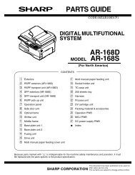
<strong>HP</strong> <strong>9250C</strong> <strong>Digital</strong> <strong>Sender</strong><strong>Service</strong> <strong>Manual</strong>
<strong>HP</strong> <strong>9250C</strong> <strong>Digital</strong> <strong>Sender</strong><strong>Service</strong> <strong>Manual</strong>
Copyright information© 2007 Copyright Hewlett-PackardDevelopment Company, L.P.Reproduction, adaptation, or translationwithout prior written permission is prohibited,except as allowed under the copyright laws.Trademark CreditsLinux is a U.S. registered trademark of LinusTorvalds.Microsoft ® , Windows ® , and Windows NT ®are U.S. registered trademarks of MicrosoftCorporation.The information contained herein is subjectto change without notice.The only warranties for <strong>HP</strong> products andservices are set forth in the express warrantystatements accompanying such productsand services. Nothing herein should beconstrued as constituting an additionalwarranty. <strong>HP</strong> shall not be liable for technicalor editorial errors or omissions containedherein.Part number: CB472-90938Edition 1, 3/2007
Table of contents1 Device informationChapter contents .................................................................................................................................. 1Device information ................................................................................................................................ 2Where to get more information ............................................................................................ 2Features ............................................................................................................................................... 4Software features ................................................................................................................................. 5Device parts ......................................................................................................................................... 6Use the control panel ........................................................................................................................... 8Control-panel layout ............................................................................................................. 8Device software .................................................................................................................................. 10<strong>Digital</strong>-sender software ...................................................................................................... 10Paper handling ................................................................................................................................... 112 Installation and configurationChapter contents ................................................................................................................................ 13Prepare the site .................................................................................................................................. 14System requirements ......................................................................................................................... 14Unpack the device .............................................................................................................................. 153 MaintenanceChapter contents ................................................................................................................................ 17Replace supplies and parts ................................................................................................................ 18Replace the mylar sheet .................................................................................................... 18Replace the ADF Maintenance Kit ..................................................................................... 19Clean the device ................................................................................................................................. 20Clean the exterior .............................................................................................................. 20Clean the glass .................................................................................................................. 20Clean the touchscreen ....................................................................................................... 20Clean the ADF delivery system ......................................................................................... 20Clean the ADF rollers ........................................................................................................ 224 Theory of operationChapter contents ................................................................................................................................ 25Basic operation ................................................................................................................................... 26Sequence of operation (scanner) ...................................................................................... 26Formatter system ............................................................................................................................... 27Sleep mode ........................................................................................................................ 27CPU ................................................................................................................................... 27ENWWiii
Memory .............................................................................................................................. 28Control panel ..................................................................................................................... 28Keyboard ........................................................................................................................... 28Scanner controller board ................................................................................................... 28Engine control system ........................................................................................................................ 28Engine power supply circuit ............................................................................................... 28Flatbed unit and ADF system ............................................................................................................. 29Electrical system ................................................................................................................ 29Motors and fans ................................................................................................................. 30Optical assembly ............................................................................................................... 30ADF feed system ............................................................................................................... 32Jam detection .................................................................................................................... 335 Removal and replacementRemoval and replacement strategy .................................................................................................... 36Required tools .................................................................................................................... 36Before performing service .................................................................................................. 36After completing service .................................................................................................... 36Screws that are used in the digital sender ......................................................................... 37User-replaceable parts ....................................................................................................................... 38Separation pad .................................................................................................................. 39Pickup-roller cover ............................................................................................................. 41Pickup roller assembly ....................................................................................................... 43Mylar-holder assembly ....................................................................................................... 44ADF mylar shield ............................................................................................................... 46Control panel ..................................................................................................................... 47Control-panel overlays ....................................................................................................... 48Formatter assemblies ........................................................................................................ 49Hinge flaps ......................................................................................................................... 53Paper input tray ................................................................................................................. 54External components and covers ....................................................................................................... 55Keyboard ........................................................................................................................... 56Control-panel lower cover .................................................................................................. 58Control-panel upper cover ................................................................................................. 59Control-panel cover assembly ........................................................................................... 60External control-panel cable .............................................................................................. 63Output bin base cover or output bin extender .................................................................... 64Output bin paper lever ....................................................................................................... 65ADF right cover .................................................................................................................. 66ADF right-corner cover ...................................................................................................... 68ADF left cover .................................................................................................................... 69ADF left-corner cover ......................................................................................................... 71ADF rear cover .................................................................................................................. 72Scanner right cover ............................................................................................................ 73Scanner left cover .............................................................................................................. 74Scanner front cover ........................................................................................................... 75Scanner rear cover ............................................................................................................ 76Right hinge cover ............................................................................................................... 77Left hinge cover ................................................................................................................. 78Upper hinge cover ............................................................................................................. 79ivENWW
Internal components ........................................................................................................................... 80ADF assembly ................................................................................................................... 81ADF jam access latch ........................................................................................................ 83Right hinge guide ............................................................................................................... 84Left hinge guide ................................................................................................................. 85Damper cover, left damper spring, right damper spring, or damper base cover ............... 86White mylar backing or white mylar backing spring ........................................................... 87Fan filter ............................................................................................................................. 88ADF cable .......................................................................................................................... 89Separation pad case .......................................................................................................... 92Clear plastic paper guide ................................................................................................... 93White scan background ..................................................................................................... 94Scanner controller board ................................................................................................... 95Flatbed scanner assembly ................................................................................................. 96Power supply ..................................................................................................................... 99Keyboard cable ................................................................................................................ 102Power-switch assembly ................................................................................................... 105Scanner base fan ............................................................................................................. 106Power plug ....................................................................................................................... 108SCB cable ........................................................................................................................ 109Internal control-panel cable ............................................................................................. 1106 TroubleshootingTroubleshooting process .................................................................................................................. 112Initial troubleshooting checklist ........................................................................................ 112Power-on checks ............................................................................................................. 113Control-panel messages .................................................................................................................. 114Control-panel message types .......................................................................................... 114Resolve control-panel messages ..................................................................................... 114Operational issues ............................................................................................................................ 122LEDs ................................................................................................................................................. 126<strong>HP</strong> Jetdirect LEDs ........................................................................................................... 126Formatter LED ................................................................................................................. 126Clear jams ........................................................................................................................................ 127Solve repeated jams ........................................................................................................ 128Calibrate the scanner ....................................................................................................................... 129To print the calibration target ........................................................................................... 129To calibrate the scanner .................................................................................................. 130Calibrating the control panel ............................................................................................ 130Resolve e-mail problems .................................................................................................................. 132Finding the LDAP server address .................................................................................... 132Verifying an LDAP address .............................................................................................. 132Troubleshooting the LDAP Find Settings process ........................................................... 132Finding an SMTP server address .................................................................................... 133Verifying an SMTP address ............................................................................................. 133Resolve network-connectivity problems ........................................................................................... 134Embedded LAN troubleshooting ...................................................................................... 134Verifying communication over the network ...................................................................... 137<strong>Service</strong>-mode functions .................................................................................................................... 139Cold reset ........................................................................................................................ 139ENWWv
NVRAM initialization ........................................................................................................ 139Disk initialization .............................................................................................................. 140<strong>Service</strong> menu ................................................................................................................................... 141Troubleshooting tools ....................................................................................................................... 142Embedded Web server .................................................................................................... 142<strong>HP</strong> Web Jetadmin software ............................................................................................. 144Diagnostic tools ................................................................................................................................ 145Scanner tests ................................................................................................................... 145Control-panel tests ........................................................................................................... 145Upgrade the firmware ....................................................................................................................... 147Determine the current level of firmware ........................................................................... 147Download new firmware from the <strong>HP</strong> Web site ............................................................... 147Use FTP to upgrade the firmware on a direct network connection .................................. 147Use <strong>HP</strong> Web Jetadmin to upgrade the firmware ............................................................. 148Upgrade the <strong>HP</strong> Jetdirect Inside firmware ....................................................................... 149Troubleshooting diagrams ................................................................................................................ 150<strong>Digital</strong>-sender wiring diagram .......................................................................................... 150Scanner controller board diagram ................................................................................... 150Parts used in troubleshooting .......................................................................................... 1527 Parts and diagramsOrdering parts and supplies ............................................................................................................. 156How to use the parts diagrams and lists .......................................................................................... 156Screws that are used in the digital sender ....................................................................................... 157Related documentation and software ............................................................................................... 158Customer-replaceable components ................................................................................................. 160ADF components .............................................................................................................................. 168Scanner and bottom assemblies ...................................................................................................... 184Alphabetical parts list ....................................................................................................................... 200Numerical parts list ........................................................................................................................... 206Appendix A <strong>Service</strong> and supportHewlett-Packard limited warranty statement .................................................................................... 213Customer self repair warranty service .............................................................................................. 214Hewlett-Packard limited warranty statement for software ................................................................ 215Availability of support and service .................................................................................................... 216<strong>HP</strong> maintenance agreements ........................................................................................................... 216Next-Day Onsite <strong>Service</strong> ................................................................................................. 216Appendix B SpecificationsPhysical specifications ..................................................................................................................... 218Electrical specifications .................................................................................................................... 218Power consumption specifications ................................................................................................... 218Environmental specifications ........................................................................................................... 219Acoustic emissions ........................................................................................................................... 219Appendix C Regulatory informationFCC regulations ............................................................................................................................... 222Environmental Product Stewardship program .................................................................................. 223viENWW
Protecting the environment .............................................................................................. 223Ozone production ............................................................................................................ 223Power consumption ......................................................................................................... 223Plastics ............................................................................................................................ 223Material restrictions .......................................................................................................... 223Disposal of waste equipment by users in private households in the European Union .... 224Material Safety Data Sheet (MSDS) ................................................................................ 224For more information ....................................................................................................... 224Declaration of conformity .................................................................................................................. 225Country-/region-specific safety statements ...................................................................................... 226Canadian DOC regulations .............................................................................................. 226VCCI statement (Japan) .................................................................................................. 226EMI statement (Korea) ..................................................................................................... 226Index ................................................................................................................................................................. 227ENWWvii
viiiENWW
List of tablesTable 5-1 Common fasteners that are used in this digital sender .................................................................... 37Table 6-1 Control-panel messages ................................................................................................................ 114Table 7-1 Common fasteners ......................................................................................................................... 157Table 7-2 Related documentation and software ............................................................................................ 159Table 7-3 Customer-replaceable components ............................................................................................... 161Table 7-4 Control-panel overlays ................................................................................................................... 163Table 7-5 Maintenance kits ............................................................................................................................ 165Table 7-6 Memory .......................................................................................................................................... 167Table 7-7 ADF Assembly ............................................................................................................................... 169Table 7-8 ADF base assembly ....................................................................................................................... 171Table 7-9 Separation pad case ...................................................................................................................... 173Table 7-10 Pickup roller assembly ................................................................................................................. 175Table 7-11 Control-panel cover assembly ...................................................................................................... 177Table 7-12 Control-panel assembly ............................................................................................................... 179Table 7-13 ADF left cover .............................................................................................................................. 181Table 7-14 ADF input tray assembly .............................................................................................................. 183Table 7-15 Scanner assembly ........................................................................................................................ 185Table 7-16 Bottom unit assembly ................................................................................................................... 187Table 7-17 Power plug ................................................................................................................................... 189Table 7-18 Top formatter ................................................................................................................................ 191Table 7-19 Fan assembly ............................................................................................................................... 193Table 7-20 Keyboard assembly ...................................................................................................................... 195Table 7-21 Lower cover assembly ................................................................................................................. 197Table 7-22 Scanner rear cover ....................................................................................................................... 199Table 7-23 Alphabetical parts list ................................................................................................................... 200Table 7-24 Numerical parts list ....................................................................................................................... 206Table B-1 Physical specifications ................................................................................................................... 218Table B-2 Electrical specifications .................................................................................................................. 218Table B-3 Power consumption (average, in watts) ........................................................................................ 218Table B-4 Environmental specifications ........................................................................................................ 219Table B-5 Acoustic emissions ........................................................................................................................ 219ENWWix
xENWW
List of figuresFigure 1-1 Control-panel layout .......................................................................................................................... 8Figure 4-1 Scanner assembly electrical structure ............................................................................................ 29Figure 4-2 Scan carriage components ............................................................................................................. 30Figure 4-3 Optical assembly ............................................................................................................................. 31Figure 4-4 ADF paper path and sensors .......................................................................................................... 32Figure 5-1 Removing the separation pad (1 of 3) ............................................................................................ 39Figure 5-2 Removing the separation pad (2 of 3) ............................................................................................ 39Figure 5-3 Removing the separation pad (3 of 3) ............................................................................................ 40Figure 5-4 Removing the paper input tray (1 of 2) ........................................................................................... 41Figure 5-5 Removing the pickup roller assembly (2 of 3) ................................................................................. 41Figure 5-6 Removing the pickup-roller cover (2 of 2) ....................................................................................... 42Figure 5-7 Removing the pickup roller assembly (1 of 3) ................................................................................. 43Figure 5-8 Removing the pickup roller assembly (2 of 3) ................................................................................. 43Figure 5-9 Removing the pickup roller assembly (3 of 3) ................................................................................. 43Figure 5-10 Removing the mylar-holder assembly (1 of 3) .............................................................................. 44Figure 5-11 Removing the mylar-holder assembly (2 of 3) .............................................................................. 44Figure 5-12 Removing the mylar-holder assembly (3 of 3) .............................................................................. 45Figure 5-13 Replacing the ADF mylar shield (4 of 7) ....................................................................................... 46Figure 5-14 Replacing the ADF mylar shield (5 of 7) ....................................................................................... 46Figure 5-15 Removing the control panel (1 of 2) .............................................................................................. 47Figure 5-16 Removing the control panel (2 of 2) .............................................................................................. 47Figure 5-17 Removing the control-panel overlays ........................................................................................... 48Figure 5-18 Removing the formatter cage ........................................................................................................ 49Figure 5-19 Removing the hard drive (1 of 2) .................................................................................................. 50Figure 5-20 Removing the hard drive (2 of 2) .................................................................................................. 50Figure 5-21 Removing the hard-disk drive cables (1 of 2) ............................................................................... 51Figure 5-22 Removing the hard-disk drive cables (2 of 2) ............................................................................... 51Figure 5-23 Removing the memory DIMM ....................................................................................................... 52Figure 5-24 Removing the hinge flaps ............................................................................................................. 53Figure 5-25 Removing the pickup-roller cover (1 of 2) ..................................................................................... 54Figure 5-26 Removing the paper input tray (2 of 2) ......................................................................................... 54Figure 5-27 Removing the keyboard (1 of 3) ................................................................................................... 56Figure 5-28 Removing the keyboard (2 of 3) ................................................................................................... 56Figure 5-29 Removing the keyboard (3 of 3) ................................................................................................... 57Figure 5-30 Removing the control-panel lower cover ...................................................................................... 58Figure 5-31 Removing the control-panel upper cover ...................................................................................... 59Figure 5-32 Removing the control-panel cover assembly (1 of 6) ................................................................... 60Figure 5-33 Removing the control-panel cover assembly (2 of 6) ................................................................... 60Figure 5-34 Removing the control-panel cover assembly (3 of 6) ................................................................... 61ENWWxi
Figure 5-35 Removing the control-panel cover assembly (4 of 6) ................................................................... 61Figure 5-36 Removing the control-panel cover assembly (5 of 6) ................................................................... 62Figure 5-37 Removing the control-panel cover assembly (6 of 6) ................................................................... 62Figure 5-38 Removing the external control-panel cable .................................................................................. 63Figure 5-39 Removing the output bin base cover or output bin extender ........................................................ 64Figure 5-40 Removing the output bin paper lever ............................................................................................ 65Figure 5-41 Removing the ADF right cover (1 of 3) ......................................................................................... 66Figure 5-42 Removing the ADF right cover (2 of 3) ......................................................................................... 66Figure 5-43 Removing the ADF right cover (3 of 3) ......................................................................................... 67Figure 5-44 Removing the ADF right-corner cover .......................................................................................... 68Figure 5-45 Removing the ADF left cover (1 of 3) ............................................................................................ 69Figure 5-46 Removing the ADF left cover (2 of 3) ............................................................................................ 69Figure 5-47 Removing the ADF left cover (3 of 3) ............................................................................................ 70Figure 5-48 Removing the ADF left-corner cover ............................................................................................. 71Figure 5-49 Removing the ADF rear cover ...................................................................................................... 72Figure 5-50 Removing the scanner right cover ................................................................................................ 73Figure 5-51 Removing the scanner left cover .................................................................................................. 74Figure 5-52 Removing the scanner front cover ................................................................................................ 75Figure 5-53 Removing the scanner rear cover ................................................................................................. 76Figure 5-54 Removing the right hinge cover .................................................................................................... 77Figure 5-55 Removing the left hinge cover ...................................................................................................... 78Figure 5-56 Removing the upper hinge cover .................................................................................................. 79Figure 5-57 Removing the ADF assembly (1 of 3) ........................................................................................... 81Figure 5-58 Removing the ADF assembly (2 of 3) ........................................................................................... 81Figure 5-59 Removing the ADF assembly (3 of 3) ........................................................................................... 82Figure 5-60 Removing the jam access latch .................................................................................................... 83Figure 5-61 Removing the right hinge guide .................................................................................................... 84Figure 5-62 Removing the left hinge guide ...................................................................................................... 85Figure 5-63 Removing the damper cover ......................................................................................................... 86Figure 5-64 Removing the white mylar backing or white mylar backing spring (1 of 2) ................................... 87Figure 5-65 Removing the white mylar backing or white mylar backing spring (2 of 2) ................................... 87Figure 5-66 Removing the fan filter .................................................................................................................. 88Figure 5-67 Removing the ADF cable (1 of 5) .................................................................................................. 89Figure 5-68 Removing the ADF cable (2 of 5) .................................................................................................. 89Figure 5-69 Removing the ADF cable (3 of 5) .................................................................................................. 90Figure 5-70 Removing the ADF cable (4 of 5) .................................................................................................. 90Figure 5-71 Removing the ADF cable (5 of 5) .................................................................................................. 91Figure 5-72 Removing the separation pad case .............................................................................................. 92Figure 5-73 Removing the clear plastic paper guide (1 of 2) ........................................................................... 93Figure 5-74 Removing the clear plastic paper guide (2 of 2) ........................................................................... 93Figure 5-75 Removing the white scan background .......................................................................................... 94Figure 5-76 Removing the scanner controller board (1 of 2) ........................................................................... 95Figure 5-77 Removing the scanner controller board (2 of 2) ........................................................................... 95Figure 5-78 Removing the flatbed scanner assembly (1 of 4) ......................................................................... 96Figure 5-79 Removing the flatbed scanner assembly (2 of 4) ......................................................................... 97Figure 5-80 Removing the flatbed scanner assembly (3 of 4) ......................................................................... 97Figure 5-81 Removing the flatbed scanner assembly (4 of 4) ......................................................................... 98Figure 5-82 Removing the power supply (1 of 6) ............................................................................................. 99Figure 5-83 Removing the power supply (2 of 6) ............................................................................................. 99Figure 5-84 Removing the power supply (3 of 6) ........................................................................................... 100xiiENWW
xivENWW
1 Device informationChapter contents●Device information●●●●●●FeaturesSoftware featuresDevice partsUse the control panelDevice softwarePaper handlingENWW Chapter contents 1
Device informationThe <strong>HP</strong> <strong>Digital</strong> <strong>Sender</strong> 9250c converts black-and-white and color documents, drawings, andphotographs into an electronic form and then distributes them directly to several kinds of destinations.You can also install the included <strong>HP</strong> <strong>Digital</strong> Sending Software (<strong>HP</strong> DSS) program to use advanced digitalsending features such as send-to-workflow with optical character recognition (OCR).Installing the device is simply a matter of connecting it to your network and configuring the digital-sendingfeatures. The digital sender operates as a standalone unit on the network and does not require networkprivileges for administration.Where to get more informationThe following table outlines the digital sending features that are available, and where to find moreinformation about these features. All of the documentation listed in this table can be found on thedocumentation CD that came in the box with the device.Feature Description For more informationScan to E-mailScan to FolderScan a document and send it to any e-mailaddress.Scan a document to a network folder. Morethan one folder destination can beconfigured.User guide or DSS support guideEmbedded Web Server (EWS) user guideAddress Book for E-mail andFaxEnter names and e-mail addresses or namesand fax numbers for e-mail and fax recipientsinto the device's address book. This featurecan also be used to manage the fax speeddials list.●●●User guideEWS user guide (for detailedinformation)DSS support guideUser PIN AuthenticationLDAP AddressingLDAP AuthenticationKerberos AuthenticationDSS LAN FaxEnter names and personal identificationnumbers (PIN) so that only authorized userscan use specific features of the device.Configure the device to search an LDAP(Lightweight Directory Access Protocol)directory for names and e-mail addresses.This feature makes the addressing of send toe-mail jobs easier.Configure the device to require userauthentication to use specific devicefeatures. This feature relies on an existingLDAP infrastructure, and can be configuredto support LDAP over a Secure SocketsLayer (SSL).Configure the device to require userauthentication to use specific features of thedevice. This feature relies on an existingKerberos Realm infrastructure. A MicrosoftWindows Domain environment supportsKerberos natively.Use the device to route fax jobs via anexisting local area network (LAN) faxinfrastructure.EWS user guideEWS user guide or DSS support guideEWS user guideEWS user guideDSS support guide2 Chapter 1 Device information ENWW
Feature Description For more informationDSS Send to FolderDSS WorkflowDSS Windows NegotiatedAuthenticationDSS LDAP AuthenticationScan a document to a network folder. Morethan one folder destination can beconfigured.Scan a document and capture informationabout the scanned document by promptingthe user. The document can then be routedto another application. This feature can beconfigured to use OCR (optical characterrecognition).Configure the device to require userauthentication to use specific features of thedevice. This feature relies on an existingMicrosoft Windows domain infrastructure.Configure the device to require userauthentication to use specific features of thedevice. This feature relies on an existingLDAP infrastructure.DSS support guideDSS support guideDSS support guideDSS support guideENWW Device information 3
FeaturesThe digital sender includes the following features:●●●●●●●<strong>Digital</strong> sending—Send scanned files to e-mail addresses and network folders. Advanced digitalsendingfunctions are carried out by the <strong>HP</strong> <strong>Digital</strong> Sending Software (<strong>HP</strong> DSS), which is includedwith the device.ADF(automatic document feeder)—The legal-size ADF accepts up to 50 pages, and includes builtinduplexing for scanning both sides of a double-sided document.Interactive touchscreen control panel—Intuitive onscreen menus and wizards help you tocomplete digital-sending tasks.Flatbed scanner—The letter/A4-size scanner can scan in both black-and-white and color, with theability to scan up to 1 mm (0.04 inch) from the paper edge.Memory—The device comes standard with 256 megabytes (MB) of random access memory(RAM).Hard disk—The device includes a 40-gigabyte (GB) internal hard drive for storing documents andsettings.Connectivity—The device provides a 10/100Base-T port, through Jetdirect Inside an <strong>HP</strong> JetdirectFast Ethernet port, and an enhanced input/output (EIO) expansion slot for connectivity.4 Chapter 1 Device information ENWW
Software featuresThe <strong>HP</strong> DSS program supports the digital sender by providing the following features:●●●●●Send to e-mail—Scan a document and send it to one or more e-mail recipients in the form ofa .PDF, .JPEG, .TIFF, or .MTIFF file.Send to secondary (secure) e-mail—Send a document by using a secure third-party e-mailsolution.Send to fax—Scan a document and send it to a local area network (LAN) fax, Internet fax, orWindows® 2000 fax destination. (This device does not have analog fax capability.)Send to workflow—Scan a document and save it to a network folder or file transfer protocol (FTP)site along with a file containing additional information about the document. A third-party softwareprogram can then retrieve and decipher the information, and perform the appropriate operation onthe scanned image. A printer can also be set up as a workflow destination, so that scanneddocuments can be printed.Send to network folder—Scan a document and send it to a folder on the network.ENWW Software features 5
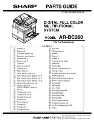
Device partsBefore using the digital sender, familiarize yourself with its parts.1234561 Control panel2 Jam release button3 Output bin4 ADF input bin5 Keyboard (pull to open)6 On/off switch7 ADF cable8 Control-panel cable9 10/100Base-T network port10 EIO slot11 USB host port (for third-party devices only)12 USB device port (for firmware upgrades only)13 Power connector6 Chapter 1 Device information ENWW
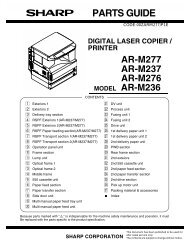
14151614 Scanner lock15 Serial number16 Scanner glassENWW Device parts 7
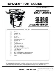
Use the control panelThe control panel has a VGA touchscreen that provides access to all device functions. Use the buttonsand numeric keypad to control jobs and the device status. The LEDs indicate overall device status.Control-panel layoutThe control panel includes a touchscreen graphical display, job-control buttons, a numeric keypad, andthree light-emitting diode (LED) status lights.Figure 1-1 Control-panel layout1 Attention light The Attention light indicates that thedevice has a condition that requiresintervention, such as an error messageon the touchscreen.2 Data light The Data light indicates that the device isreceiving data.3 Ready light The Ready light indicates that the deviceis ready to begin processing a job.4 Brightness-adjustment dial Turn the dial to control the brightness ofthe touchscreen.5 Touchscreen graphical display Use the touchscreen to open and set upall device functions.6 Numeric keypad Use the keypad to type numeric values,such as a fax number.7 Sleep button and light If the device is inactive for a long periodof time, it automatically enters Sleepmode. To place the device into Sleepmode or to reactivate the device, pressthe Sleep button. When the light isglowing, the device is in Sleep mode.8 Reset button Resets the job settings to factory or userdefineddefault values.8 Chapter 1 Device information ENWW
9 Stop button Stops the active job. While stopped, thecontrol panel shows the options for thestopped job (for example, if you pressStop while the device is processing an e-mail job, the control panel messageprompts you to cancel or resume thejob).10 Start button and light Starts digital sending, or resumes a jobthat has been interrupted. When the lightis glowing, the device is ready to startscanning.ENWW Use the control panel 9
Device software<strong>Digital</strong>-sender softwareTo take advantage of advanced digital-sender features such as scanning with OCR or sending to aworkflow, you can install the <strong>HP</strong> <strong>Digital</strong> Sending Software Version 4.0 (<strong>HP</strong> DSS) that is provided on aCD-ROM with the device. This software runs as a service on a network server. It is not necessary toinstall any software or drivers on individual user's computers.See the <strong>HP</strong> <strong>Digital</strong> Sending Software Support Guide on the documentation CD for software installationand configuration instructions.The most recent software updates are available on the Internet at www.hp.com/support/dss.10 Chapter 1 Device information ENWW
Paper handlingThe <strong>HP</strong> <strong>Digital</strong> <strong>Sender</strong> 9250c supports the following standard media sizes:●●●●●●Letter: 215.9 x 279 mm (8.5 x 11 inches)Executive: 190 x 254 mm (7.5 x 10 inches)A4: 210 x 297 mm (8.3 x 11.7 inches)A5: 148 x 210 mm (5.83 x 8.27 inches)B5: 176 x 250 mm (6.9 x 9.8 inches)Legal (from the ADF only): 215.9 x 355.6 mm (8.5 x 14 inches)Paper weight: 60 to 120 g/m2 (16 to 32 lb)Up to 50 sheets of paper can be stacked in the ADF, up to a maximum height of 5 mm (0.2 inch).ENWW Paper handling 11
12 Chapter 1 Device information ENWW
2 Installation and configurationChapter contents●Prepare the site●●System requirementsUnpack the deviceENWW Chapter contents 13
Prepare the siteSelect a well-ventilated, dust-free area to install the device. Place the device on a sturdy surface.452.62 mm(17.82 inches)724.20 mm(28.51 inches)720.85 mm(28.38 inches)720.85 mm(28.38 inches)System requirementsTo install the <strong>HP</strong> <strong>Digital</strong> <strong>Sender</strong> 9250c, the computer system must have the following features:●●Fast Ethernet 100Base-TX or Ethernet 10Base-TAccess to an SMTP e-mail gatewayNOTE: <strong>HP</strong> highly recommends establishing SMTP gateway on your own local area network. However,the device can be configured for e-mail functionality even if mail services are provided by an outsideInternet service provider (ISP) over a digital subscription line (DSL).14 Chapter 2 Installation and configuration ENWW
Unpack the deviceRemove all shipping bags, tape, and packing material.1 2345 61 Getting started guide (use the getting started guide for installation)2 <strong>Digital</strong> sender documentation and <strong>HP</strong> DSS optional software3 <strong>Digital</strong> sender4 Control-panel overlays (if included)5 Power cord6 Calibration sheetENWW Unpack the device 15
16 Chapter 2 Installation and configuration ENWW
3 MaintenanceChapter contents●Replace supplies and parts●Clean the deviceENWW Chapter contents 17
Replace supplies and partsReplace the mylar sheetIf you start to see vertical streaks on the scanned images, you might need to replace the mylar sheet atthe base of the ADF. The device ships with an envelope containing three extra mylar sheets andinstallation instructions. The envelope is in a pocket behind the ADF vinyl backing, as shown in thefollowing figure.AaBbCcAaBbCcAaBbCcAaBbCcAaBbCcFollow the instructions that come in the envelope to replace the mylar sheet.NOTE: If necessary, you can order extra mylar sheet replacement kits from your <strong>HP</strong> salesrepresentative. The <strong>HP</strong> product number is Q6496A.18 Chapter 3 Maintenance ENWW
Replace the ADF Maintenance KitThe device notifies you when it is time to replace the ADF Maintenance Kit by showing a message onthe control-panel display. You can view the remaining life of the Maintenance Kit at any time by pressingthe Supplies Status button on the control panel or visiting the EWS Supplies Status page (see theembedded Web server guide on the device CD).The ADF Maintenance Kit includes the following items:●●●●One pickup roller assemblyOne separation padOne mylar sheet kitAn instruction bookletFollow the instructions that come with the kit to install it.After replacing the kit, reset the New Document Feeder Kit setting.1. On the Home screen, touch Administration.2. Scroll down and touch Resets.3. Touch Reset Supplies.4. Touch New Document Feeder Kit.5. Touch Yes, and then touch Save.ENWW Replace supplies and parts 19
Clean the deviceDuring the scanning process, paper and dust particles can accumulate inside the device. Over time,this buildup can cause problems, such as specks on scanned documents.Clean the exteriorUse a soft, damp, lint-free cloth to wipe dust, smudges, and stains off of the exterior of the device.Clean the glass●●Clean the glass only if dirt is visible, or if you see poor scan quality (such as streaking).Clean the glass surface by wiping it gently with a clean, damp, lint-free cloth. Use an ammoniabasedsurface cleaner to dampen the cloth.CAUTION: Do not pour or spray liquids directly onto the glass. Do not press hard on the glass surface,as this could break the glass.Clean the touchscreenClean the touchscreen when needed to clear away fingerprints or dust build-up. To clean it, wipe thetouchscreen gently with a clean, water-dampened, lint-free cloth.CAUTION: Use water only. Solvents or cleaners can damage the touchscreen. Do not pour or spraywater directly onto the touchscreen.Clean the ADF delivery system1. Open the scanner lid.2. Locate the white, vinyl ADF backing.20 Chapter 3 Maintenance ENWW
3. Locate the white, vinyl calibration strips.4. Clean the ADF backing and the calibration strips by wiping them with a clean, damp, lint-free cloth.Use an ammonia-based surface cleaner to dampen the cloth.5. Close the scanner lid.ENWW Clean the device 21
Clean the ADF rollersYou should clean the rollers in the ADF if you are experiencing misfeeds or if your originals show marksas they exit the ADF.CAUTION:Cleaning the rollers too frequently could introduce dust into the device.1. Open the scanner lid.2. Locate the rollers near the vinyl calibration strips.3. Wipe the rollers gently with a clean, water-dampened, lint-free cloth.CAUTION:Do not pour water directly onto the rollers. Doing so might damage the device.4. Close the scanner lid.5. Push the release button to open the ADF cover.22 Chapter 3 Maintenance ENWW
6. Locate the rollers.7. Wipe the rollers with a clean, water-dampened, lint-free cloth.CAUTION:Do not pour water directly onto the rollers. Doing so might damage the device.8. Locate the separation pad.9. Wipe the pad with a clean, water-dampened, lint-free cloth.10. Close the ADF cover.ENWW Clean the device 23
24 Chapter 3 Maintenance ENWW
4 Theory of operationChapter contents●Basic operation●●●Formatter systemEngine control systemFlatbed unit and ADF systemENWW Chapter contents 25
Basic operationAll high-level digital sender processes are routed through the formatter, which processes images andcommunicates with other devices.The basic digital sender operation can be divided into three systems:●●●The engine control system, which includes the power supply and the scanner controller boardThe pickup-and-feed system, which consists of various rollers and transports the media throughthe ADFThe scanner system, which scans documents and sends them to the formatter in the form of dataSequence of operation (scanner)Period (sequence)Power onInitializationStandbyScanDescriptionThe period of time from when the digital sender power is turned on until the main motor beginsto rotate.The period of time after the initial power-on sequence and before the digital sender is readyto scan. During this time, the scanner and ADF initialization is completed, scanner calibrationis performed, and the ADF checks for media in the input tray.The period of time from the end of the initialization sequence until a request for a scan. Duringthis time, the scan carriage is in the Home position and the digital sender might go into Sleepmode.The period of time immediately following a request for a scan. The scanner fan turns on, thescan start position is adjusted, the digital sender performs the scan, and data is sent to theformatter.26 Chapter 4 Theory of operation ENWW
Formatter systemThe formatter is responsible for the following procedures:●●●●●Controlling Sleep modeReceiving and processing scan dataMonitoring control-panel functions and relaying digital-sender status information (through thecontrol panel and the network)Developing and coordinating data placement and timing with the scanner controller boardCommunicating over the networkSleep modeThe formatter provides the electrical interface and mounting locations for one EIO card, one memoryDIMM, and the hard-disk drive. The formatter also provides two internal USB host ports (for third-partydevices), one external USB host port, and one external USB device port.This feature conserves power after the digital sender has been idle for an adjustable period of time.When the digital sender is in Sleep mode, the control-panel backlight is turned off, but the digital senderretains all settings. The default setting is for Sleep mode to be enabled, and the digital sender entersthe Sleep mode after a 30-minute idle time. Sleep mode can also be turned off from theAdministration menu.The digital sender exits Sleep mode and enters the warm-up cycle when any of the following occurs:●●●●A PML or PJL command is receivedYou touch the control-panel touchscreen or press a key on the keyboard or a button on the controlpanelThe top cover is openedMedia is placed in the input trayNOTE: <strong>Digital</strong>-sender error messages override the Sleep message. The digital sender enters Sleepmode at the appropriate time, but the error message continues to appear.CPUThe formatter incorporates a 480 MHz MIPS processor.ENWW Formatter system 27
MemoryThe formatter system contains the digital sender memory, which is divided into several components.This section describes each memory component.NOTE: If the digital sender encounters a problem when managing available memory, a clearablewarning message appears on the control panel.●●●Hard-disk drive. The digital sender comes standard with a hard disk that has a capacity of 40 GBor greater. The hard disk is used to store settings.Random-access memory on the formatter. The random-access memory (RAM) contains thescanned image. Memory capacity can be increased by adding a dual inline memory module (DIMM)to the formatter or replacing an existing DIMM with a larger DIMM. In most cases, additionalmemory might be required to use the digital sender with certain other devices, such as third-partydevices. Typically, adding memory will not increase the performance of the device.Nonvolatile memory. The digital sender uses nonvolatile memory (NVRAM) to store I/Oinformation and other permanent information, such as page counts and serial number. Thecontents of NVRAM are retained when the digital sender is turned off or disconnected.Control panelKeyboardThe control panel contains both touchscreen and hard keys, and sends user commands to the formatter.The keyboard tray contains a keyboard for entering e-mail addresses and other data.Scanner controller boardThe scanner controller board sends data to the formatter and receives commands from the formatter.The scanner controller board controls motors, fans, and sensors.Engine control systemEngine power supply circuitThe power supply consists of a low-voltage circuit. The low-voltage circuit provides uninterrupted 5 volt(V) and 3.3 V power to the formatter, and provides 24 V, 5 V, and 3.3 V power to the scanner controllerboard.28 Chapter 4 Theory of operation ENWW
Flatbed unit and ADF systemElectrical systemThe scanner-assembly electrical system consists of the following components:●●●●The charged-coupled device (CCD) PCA (optical assembly)The inverterThe scanner controller boardThe ADF intermediate boardFigure 4-1 Scanner assembly electrical structure on page 29 shows the scanner-assembly electricalstructure.Figure 4-1 Scanner assembly electrical structureScanner/controllerboardInverterPCACarriage home sensorCarriage (Optical scan unit)CCDScanningLampFan drive circuitMotor drive circuitADF open sensorFlatbed fanCarriage motorImagescannerMotor drive circuitMotor drive circuitSolenoid drive circuitFan drive circuitFeed motorRead motorSolenoidADF intermediatePCAADFADF fanCover open sensorEmpty sensorRegistration sensorRead sensorExit sensorBin full sensorPaper detectFormatter+24VSENPW RENWW Flatbed unit and ADF system 29
Motors and fansThe scanner assembly has three motors and three fans. The motors are stepping motors, which drivethe components inside the scanner assembly. The fans cool various motors and components in thesystem.Name Purpose Type Rotation Failure detectionScanner motor (flatbedmotor)Feed motorRead motorDrives the scannercarriage unitDrives the pickup, theseparation, andregistration rollersDrives the feed anddelivery rollersStepping motor Varies NoStepping motor Varies NoStepping motor Varies NoPower supply fan Cools the power supply Fan Exhaust NoScanner motor fanADF fanCools the scanner lampand the CCDCools the feed motorand the read motorFan Intake YesFan Exhaust YesFormatter fan Cools the formatter Fan Exhaust YesOptical assemblyThe optical assembly contains the lamp, five mirrors, a lens, and the charged coupled device (CCD).Figure 4-2 Scan carriage componentsDocumentInvertercircuitScanning lampreflectorFourth mirrorThird mirrorGlassCPUScannerControllerFifth mirrorFirst mirrorLensSecond mirrorCCDThe scanner lamp illuminates a small strip of the document that is called the raster line. The mirrorsdirect the light through the lens to the CCD. The CCD senses and records the light, creating an analogrepresentation of the raster line. If the ADF is being used, the document then advances in the ADF to30 Chapter 4 Theory of operation ENWW
the next raster line. If the flatbed is being used, the carriage advances to the next raster line. Thisadvancing and collection process continues to the end of the sheet.Figure 4-3 Optical assemblyOptical unit home positiondetection sensorSensor flagMOTOR CONTROLsignalsOptical unitCPUmotor drive circuitMOTOR DRIVEsignalsMotor rotates inthe reverse directionMotor rotates inthe normal directionUnit moves backwardcarriageUnit moves forwardglassOptical unitMotorOptical unit motorThe image data is collected on the scanner controller board, where it is processed and sent to theformatter.ENWW Flatbed unit and ADF system 31
ADF feed systemThe ADF has built-in duplexing capability for scanning two-sided documents. Pages from the originaldocument enter the ADF from the ADF input tray. A separation roller and separation pad work togetherto separate the top sheet from the stack. The page passes through a set of registration rollers and twosets of feed rollers that advance the page. A set of delivery rollers delivers the page to the ADF outputbin. A bin-full sensor detects when the ADF output bin is full and stops the feed mechanism until the binis emptied.Figure 4-4 ADF paper path and sensorsRead MotorFeed MotorSeparation rollerEmpty sensorCover open sensorRegistration sensorPickup rollerRegistration rollerFeed rollerSeparation padADF input trayDelivery rollerRead sensorScanning positionDelivery trayExit sensorBin full sensorglassOptical unitCarriageMotor32 Chapter 4 Theory of operation ENWW
Jam detectionWhen the sensors inside the ADF detect a jam, the feed and read motors immediately stop. A signal issent to the scanner controller board, which notifies the formatter. An error message appears on thecontrol-panel display.To clear a jam, open the jam-access cover and remove the media. When sensors do not detect mediaafter entering the jam state, the jam message is cleared from the control-panel display.Residual-media jamDuring the initialization sequence or after the ADF jam cover has been opened and closed, if theregistration sensor, read sensor, or exit sensor detects the presence of media, the scanner controllerboard determines that a residual-media jam has occurred.ADF pickup jamADF jamIf the leading edge of the media did not reach the registration sensor within a specific period of time, thescanner controller board determines that an ADF pickup jam has occurred.ADF jams can occur in three places inside the ADF.Registration-sensor jamRead-sensor jamExit-sensor jamIf the registration sensor does not detect the trailing edge of the media after the leading edge reachesthe scan-ready position, the scanner-controller board determines that an ADF jam has occurred.Also, when the scanner duplexer is in use, if the registration sensor does not detect the leading edgeof the media after a specific period of time after media enters the duplexer, the scanner-controller boarddetermines that an ADF jam has occurred.If the read sensor does not detect the leading edge of the media within a specific period of time, or ifthe read sensor does not detect the trailing edge of the media within a specific period of time after itdetects the leading edge, the scanner-controller board determines that an ADF jam has occurred.If the exit sensor does not detect the leading edge of the media within a specific period of time after theleading edge reaches the read sensor, or if the exit sensor does not detect the trailing edge of the mediawithin a specific period of time after the read sensor detects the trailing edge, the scanner-controllerboard determines that an ADF jam has occurred.ADF cover-open jamADF open jamIf the ADF jam-access cover is opened while media is feeding through the ADF, a jam occurs.If the ADF is opened while media is feeding through the ADF, a jam occurs.ENWW Flatbed unit and ADF system 33
34 Chapter 4 Theory of operation ENWW
5 Removal and replacementThis chapter contains information about the following topics:●●●●Removal and replacement strategyUser-replaceable partsExternal components and coversInternal componentsENWW 35
Removal and replacement strategyThis chapter describes how to remove, replace, and reassemble the major assemblies of the digitalsender. Replacement is generally the reverse of removal.WARNING! Unplug the power cord from the power outlet (at the wall receptacle) before attempting toservice the digital sender. If you do not follow this warning, severe injury can result. Certain functionalchecks during troubleshooting might require power to be supplied to the digital sender. However, allpower should be turned off and the product should be unplugged when you remove any digital senderassemblies or components. Never operate or service the digital sender when the protective cover isremoved from the laser/scanner assembly. The reflected beams, although invisible, can damage youreyes.CAUTION: The product contains components that are sensitive to electrostatic discharge (ESD).Always perform service work at an ESD-protected workstation. If an ESD-protected workstation is notavailable, discharge body static by grasping the digital sender chassis before touching an ESD-sensitivecomponent. Ground the digital sender chassis before servicing the digital sender.NOTE:To identify the left side and right side of the digital sender, face the control panel.Required tools●●●●●●●●●●#1 Phillips screwdriver#2 Phillips screwdriver#2 Phillips screwdriver with a shaft diameter of 6 mm (0.25 inch) or lessShort #2 Phillips screwdriver shaft length of 76 mm (3.0 inches)Right-angle #2 Phillips screwdriverSmall flat-blade screwdriverNeedle-nose pliersESD mat (if available; see the preceding ESD caution)Penlight (optional)Tape (optional)CAUTION:screwdriver.A pozidriv screwdriver can damage screw heads on the product. Use a #2 PhillipsBefore performing service●If possible, go to the digital sender embedded Web server and print the configuration page.After completing service●●Reconnect all cables to the product.Replace all of the accessories.● Verify that the most recent firmware is installed. See Upgrade the firmware on page 147.36 Chapter 5 Removal and replacement ENWW
Screws that are used in the digital senderThis table describes the screws that are used in the digital sender and provides guidelines to helpdetermine where each type of screw is used. The screws can vary in length depending on the thicknessof the material that is being fastened. Always note where each type of screw is located and replace eachone in its original location.NOTE: When you are disassembling the product, place the screws into the chassis holes from whichthey were removed. This prevents their loss, and ensures that the proper type and length of screw foreach location is used when the product is reassembledTable 5-1 Common fasteners that are used in this digital senderDrawing and descriptionPurposeThis screw is used to fasten metal to metal when good electrical contact is needed.This screw also provides high resistance to loosening.Phillips-head machine screw with captivestar washerThis screw is used to fasten sheet metal or plastic to plastic frames. The deep,coarsely spaced threads provide an increased holding capability while decreasingthe possibility of stripping the target hole.Phillips-head screw with self-tappingthreadsNOTE: To install a self-tapping screw, first turn it counterclockwise to align it withthe existing thread pattern, and then carefully turn it clockwise to tighten it. You willfeel resistance and hear the screw click when it engages the existing threads in thehole. Do not overtighten the screw. If a self-tapping screw-hole becomes stripped,repair the screw-hole or replace the affected assembly.This screw is used to fasten sheet metal parts to the sheet metal chassis. It spanslarge clearance holes and distributes the load by increasing the bearing surface.Phillips washer-head machine screw witha broad, flat washer attached to the screwheadScrew measurement guideENWW Removal and replacement strategy 37
User-replaceable parts●Separation pad●●●●●●●●●Pickup-roller coverPickup roller assemblyMylar-holder assemblyADF mylar shieldControl panelControl-panel overlaysFormatter assembliesHinge flapsPaper input tray38 Chapter 5 Removal and replacement ENWW
Separation pad1. Open the ADF top cover.Figure 5-1 Removing the separation pad (1 of 3)122. Raise the separation pad frame assembly.Figure 5-2 Removing the separation pad (2 of 3)ENWW User-replaceable parts 39
3. Push the bottom edge of the separation pad away from the frame.Figure 5-3 Removing the separation pad (3 of 3)4. Remove the separation pad.40 Chapter 5 Removal and replacement ENWW
Pickup-roller cover1. Open the ADF top cover.Figure 5-4 Removing the paper input tray (1 of 2)122. Open the pickup-roller cover by pressing the locking tab and rotating the top of the assembly awayfrom the ADF.Figure 5-5 Removing the pickup roller assembly (2 of 3)ENWW User-replaceable parts 41
3. Release two clips (callout 1) to remove the cover.Figure 5-6 Removing the pickup-roller cover (2 of 2)142 Chapter 5 Removal and replacement ENWW
Pickup roller assembly1. Open the ADF top cover.Figure 5-7 Removing the pickup roller assembly (1 of 3)122. Open the pickup-roller cover by pressing the locking tab and rotating the top of the assembly awayfrom the ADF.Figure 5-8 Removing the pickup roller assembly (2 of 3)3. Pull the left side (gear end) of the roller-assembly drive shaft to disengage it, and then slide theassembly toward the left of the device to remove it.Figure 5-9 Removing the pickup roller assembly (3 of 3)12ENWW User-replaceable parts 43
Mylar-holder assembly1. Open the ADF/scanner assembly and release the locking tabs on the mylar-holder assembly.Figure 5-10 Removing the mylar-holder assembly (1 of 3)The mylar-holder assembly should drop open.Figure 5-11 Removing the mylar-holder assembly (2 of 3)44 Chapter 5 Removal and replacement ENWW
2. Remove the mylar-holder assembly by unclipping two clips (callout 1) and pulling the assemblytoward you.Figure 5-12 Removing the mylar-holder assembly (3 of 3)1ENWW User-replaceable parts 45
ADF mylar shield1. Remove the mylar-holder assembly. See Mylar-holder assembly on page 44.2. Carefully unhook the mylar shield from the four tabs on the mylar-holder assembly, and thenremove and discard the mylar shield.Figure 5-13 Replacing the ADF mylar shield (4 of 7)3. Use a dry cloth to clean the white strips inside of the mylar-holder assembly.4. Insert a new mylar shield, and clip it onto the four tabs on the mylar-holder assembly.NOTE:Make sure that you do not leave fingerprints on the new mylar shield.Figure 5-14 Replacing the ADF mylar shield (5 of 7)46 Chapter 5 Removal and replacement ENWW
Control panel1. Turn the two latches (callout 1) counterclockwise 90° until they click.Figure 5-15 Removing the control panel (1 of 2)12. Rotate the top of the control panel away from the device and disconnect one connector to free thecontrol panel from the device.Figure 5-16 Removing the control panel (2 of 2)3. Remove the control panel.ENWW User-replaceable parts 47
Control-panel overlaysUse a small flatblade screwdriver to release the two control-panel overlays.Figure 5-17 Removing the control-panel overlays48 Chapter 5 Removal and replacement ENWW
Formatter assembliesFormatter cageUnscrew the thumb screws at the back of the device and use them to pull the formatter cage out of theunit.Figure 5-18 Removing the formatter cageENWW User-replaceable parts 49
Hard-disk driveWARNING! The product contains components that are sensitive to electrostatic discharge (ESD).Always perform service work at an ESD-protected workstation. If an ESD-protected workstation is notavailable, discharge body static by grasping the device chassis before touching an ESD-sensitivecomponent. Ground the device chassis before servicing the product.1. Remove the formatter cage (see Formatter cage on page 49), open the formatter-cage door, andthen disconnect the hard-disk drive cables (callout 1) from the hard-disk drive.Figure 5-19 Removing the hard drive (1 of 2)12. Slide the hard-disk drive to the right to remove it.Figure 5-20 Removing the hard drive (2 of 2)50 Chapter 5 Removal and replacement ENWW
Hard-disk drive cablesWARNING! The product contains components that are sensitive to electrostatic discharge (ESD).Always perform service work at an ESD-protected workstation. If an ESD-protected workstation is notavailable, discharge body static by grasping the device chassis before touching an ESD-sensitivecomponent. Ground the device chassis before servicing the product.1. Remove the formatter cage (see Formatter cage on page 49), open the formatter-cage door, andthen disconnect the hard-disk drive cables from the hard-disk drive (callout 1).Figure 5-21 Removing the hard-disk drive cables (1 of 2)12. Disconnect the hard-disk-drive cables from the formatter (callout 2).Figure 5-22 Removing the hard-disk drive cables (2 of 2)2ENWW User-replaceable parts 51
Memory DIMM1. Push down on the two tabs (callout 1) to release the memory DIMM.Figure 5-23 Removing the memory DIMM12. Lift the DIMM out of the formatter.52 Chapter 5 Removal and replacement ENWW
Hinge flapsSlide a small flat blade screwdriver between the hinge flaps (callout 1) and their housing and then gentlypry the flaps away from the device.Figure 5-24 Removing the hinge flapsENWW User-replaceable parts 53
Paper input tray1. Open the ADF top cover.Figure 5-25 Removing the pickup-roller cover (1 of 2)122. Pull the hinge out of its hole on the left side of the paper input tray, and then slide the tray towardthe left side of the device to remove the tray.Figure 5-26 Removing the paper input tray (2 of 2)54 Chapter 5 Removal and replacement ENWW
External components and covers●Keyboard●●●●●●●●●●●●●●●●●●Control-panel lower coverControl-panel upper coverControl-panel cover assemblyExternal control-panel cableOutput bin base cover or output bin extenderOutput bin paper leverADF right coverADF right-corner coverADF left coverADF left-corner coverADF rear coverScanner right coverScanner left coverScanner front coverScanner rear coverRight hinge coverLeft hinge coverUpper hinge coverENWW External components and covers 55
Keyboard1. Pull out the keyboard tray.2. Use a small flat blade screwdriver to slide four tabs (callout 1) toward the keys.Figure 5-27 Removing the keyboard (1 of 3)13. Use the screwdriver to lift the keyboard slightly, and then slowly rotate the keyboard away from thetray.Figure 5-28 Removing the keyboard (2 of 3)56 Chapter 5 Removal and replacement ENWW
4. Turn the keyboard over, disconnect one cable (callout 2), and then lift the keyboard away from thedevice.Figure 5-29 Removing the keyboard (3 of 3)2ENWW External components and covers 57
Control-panel lower cover1. Remove the control panel. See Control panel on page 47.2. Remove four screws (callout 1).Figure 5-30 Removing the control-panel lower cover13. Remove the control-panel lower cover.58 Chapter 5 Removal and replacement ENWW
Control-panel upper cover1. Remove the following items:● Control panel. See Control panel on page 47.● Control-panel lower cover. See Control-panel lower cover on page 58.2. Remove five screws (callout 1) in the back of the control panel, and pull two plastic tabs (callout 2)toward you to release the control-panel upper cover.Figure 5-31 Removing the control-panel upper cover123. Remove the control-panel upper cover.ENWW External components and covers 59
Control-panel cover assembly1. Remove the control panel. See Control panel on page 47.2. Remove three screws (callout 1).Figure 5-32 Removing the control-panel cover assembly (1 of 6)13. Slide the rear control-panel cover past the latches and remove the cover.4. Remove two screws (callout 2).Figure 5-33 Removing the control-panel cover assembly (2 of 6)260 Chapter 5 Removal and replacement ENWW
5. At the back of the device, use a flat blade screwdriver to pry two tabs (callout 3) toward you at thebottom ends of the tabs.Figure 5-34 Removing the control-panel cover assembly (3 of 6)6. Unhook the white plastic arm by gently pulling the tab toward you.Figure 5-35 Removing the control-panel cover assembly (4 of 6)7. Lift the control-panel cover assembly off of the device, rotate the front of the assembly toward theback of the device, and then set the assembly down on the work surface.ENWW External components and covers 61
8. Remove one screw (callout 4).Figure 5-36 Removing the control-panel cover assembly (5 of 6)9. Remove the scanner rear cover by firmly pulling the cover toward you.10. Remove one screw (callout 5) to release the metal wire clip, open two cable guides (callout 6), andthen disconnect one cable (callout 7) to release the control-panel cover assembly from the device.Figure 5-37 Removing the control-panel cover assembly (6 of 6)56762 Chapter 5 Removal and replacement ENWW
External control-panel cable1. Perform steps 1 through 3 of removing the control panel cover assembly. See Control-panel coverassembly on page 60.2. Remove two screws (callout 1).Figure 5-38 Removing the external control-panel cable13. Perform steps 7 through 9 of removing the control panel cover assembly.4. Remove the external control-panel cable.NOTE:During reinstallation, make sure that the cable is routed correctly.ENWW External components and covers 63
Output bin base cover or output bin extender1. Remove the mylar replacement kit (envelope).2. Gently peel back the white scan background far enough to uncover four screws (callout 1).NOTE:The foam backing should not tear if the white scan background is peeled back gently.3. Remove four screws (callout 1) and remove the output bin base cover or the output bin baseextender.Figure 5-39 Removing the output bin base cover or output bin extender164 Chapter 5 Removal and replacement ENWW
Output bin paper lever1. Remove the output bin base cover or the output bin extender. See Output bin base cover or outputbin extender on page 64.2. Remove the output bin paper lever.Figure 5-40 Removing the output bin paper leverENWW External components and covers 65
ADF right cover1. Open the ADF top cover.Figure 5-41 Removing the ADF right cover (1 of 3)122. Remove the paper input tray. See Paper input tray on page 54.3. Remove one screw (callout 1).Figure 5-42 Removing the ADF right cover (2 of 3)166 Chapter 5 Removal and replacement ENWW
4. Open the ADF, remove two screws (callout 2), and release one tab (callout 3).Figure 5-43 Removing the ADF right cover (3 of 3)235. Lift off the ADF right cover.NOTE:During reinstallation make sure that the rear corner of the ADF right cover is positioned first.ENWW External components and covers 67
ADF right-corner cover1. Remove the ADF right cover. See ADF right cover on page 66.2. Release two tabs (callout 1).Figure 5-44 Removing the ADF right-corner cover13. Remove the ADF right-corner cover.68 Chapter 5 Removal and replacement ENWW
ADF left cover1. Open the ADF top cover.Figure 5-45 Removing the ADF left cover (1 of 3)122. Remove one screw (callout 1) and release the arm (callout 2).Figure 5-46 Removing the ADF left cover (2 of 3)21ENWW External components and covers 69
3. Open the ADF and remove two screws (callout 3).Figure 5-47 Removing the ADF left cover (3 of 3)34. Lift off the ADF left cover.70 Chapter 5 Removal and replacement ENWW
ADF left-corner cover1. Remove the ADF left cover. See ADF left cover on page 69.2. Release two tabs (callout 1).Figure 5-48 Removing the ADF left-corner cover13. Remove the ADF left-corner cover.ENWW External components and covers 71
ADF rear cover1. Remove the following covers:● Control panel cover assembly. See Control-panel cover assembly on page 60.● ADF right cover. See ADF right cover on page 66.● ADF left cover. See ADF left cover on page 69.2. Remove three screws (callout 1).Figure 5-49 Removing the ADF rear cover13. Remove the ADF rear cover.72 Chapter 5 Removal and replacement ENWW
Scanner right cover1. Remove three screws (callout 1).Figure 5-50 Removing the scanner right cover12. Remove the scanner right cover.ENWW External components and covers 73
Scanner left cover1. Remove three screws (callout 1).Figure 5-51 Removing the scanner left cover12. Remove the scanner left cover.74 Chapter 5 Removal and replacement ENWW
Scanner front cover1. Remove the following covers:● Scanner right cover. See Scanner right cover on page 73.● Scanner left cover. See Scanner left cover on page 74.2. Remove three screws (callout 1).Figure 5-52 Removing the scanner front cover13. Remove the scanner front cover.ENWW External components and covers 75
Scanner rear cover1. Remove one screw (callout 1).Figure 5-53 Removing the scanner rear cover12. Remove the scanner rear cover by firmly pulling the cover toward you and slightly to the left. Slidethe scanner rear cover slightly left to clear the ridge on the right side.76 Chapter 5 Removal and replacement ENWW
Right hinge cover1. Remove the scanner rear cover. See Scanner rear cover on page 76.2. Remove two screws (callout 1).Figure 5-54 Removing the right hinge cover13. Remove the right hinge cover.ENWW External components and covers 77
Left hinge cover1. Remove the scanner rear cover. See Scanner rear cover on page 76.2. Remove two screws (callout 1).Figure 5-55 Removing the left hinge cover13. Remove the left hinge cover.78 Chapter 5 Removal and replacement ENWW
Upper hinge coverFirmly pry off the upper hinge cover (callout 1).Figure 5-56 Removing the upper hinge cover1ENWW External components and covers 79
Internal components●ADF assembly●●●●●●●●●●●●●●●●●●●ADF jam access latchRight hinge guideLeft hinge guideDamper cover, left damper spring, right damper spring, or damper base coverWhite mylar backing or white mylar backing springFan filterADF cableSeparation pad caseClear plastic paper guideWhite scan backgroundScanner controller boardFlatbed scanner assemblyPower supplyKeyboard cablePower-switch assemblyScanner base fanPower plugSCB cableInternal control-panel cable80 Chapter 5 Removal and replacement ENWW
ADF assembly1. Remove the scanner rear cover. See Scanner rear cover on page 76.2. Remove one screw (callout 1) from the metal cable-retaining bracket, and then remove the bracket.Figure 5-57 Removing the ADF assembly (1 of 3)13. Unclip three wire clips (callout 2) and release the wires.Figure 5-58 Removing the ADF assembly (2 of 3)2ENWW Internal components 81
4. Remove one grounding screw and wire (callout 3), and disconnect three cable connectors(callout 4).Figure 5-59 Removing the ADF assembly (3 of 3)345. Remove the ADF assembly by lifting it up and lifting the rear hinges out of their sockets.NOTE:Make sure you calibrate the scanner when necessary.82 Chapter 5 Removal and replacement ENWW
ADF jam access latch1. Remove the following covers:● Control panel cover assembly. See Control-panel cover assembly on page 60.● ADF right cover. See ADF right cover on page 66.● ADF left cover. See ADF left cover on page 69.● ADF rear cover. See ADF rear cover on page 72.2. Using your fingers or a flatblade screwdriver, separate two clips (callout 1) and shift the latch tothe right so that the notches are aligned.Figure 5-60 Removing the jam access latch13. Remove the ADF jam access latch.ENWW Internal components 83
Right hinge guide1. Remove the following covers:● ADF rear cover. See ADF rear cover on page 72.● Right hinge cover. See Right hinge cover on page 77.2. Remove five screws (callout 1).Figure 5-61 Removing the right hinge guide13. Lift the ADF up to release the right hinge guide.84 Chapter 5 Removal and replacement ENWW
Left hinge guide1. Remove the following covers:● ADF rear cover. See ADF rear cover on page 72.● Left hinge cover. See Left hinge cover on page 78.2. Remove five screws (callout 1).Figure 5-62 Removing the left hinge guide13. Pull down on the left hinge guide to remove it.ENWW Internal components 85
Damper cover, left damper spring, right damper spring, or damper basecover1. Remove the ADF right cover, or the ADF left cover, or both covers, depending on the removalobjective. See ADF right cover on page 66 or ADF left cover on page 69.2. Remove two screws (callout 1).Figure 5-63 Removing the damper cover13. Remove the damper.NOTE:Remove the damper spring cap by sliding it up through the hole.4. Repeat steps 2 and 3 to remove the damper on the other side.NOTE: During reinstallation, make sure that the oblong hole is directed toward the rear of theADF, as shown in the illustration above.NOTE: The left damper spring and the right damper spring are different. Make sure that thecorrect spring is reinstalled in the correct location.86 Chapter 5 Removal and replacement ENWW
White mylar backing or white mylar backing spring1. Open the ADF top cover.Figure 5-64 Removing the white mylar backing or white mylar backing spring (1 of 2)122. Open the mylar holder assembly.3. Push in the tab on the left side of the white mylar backing (callout 1).Figure 5-65 Removing the white mylar backing or white mylar backing spring (2 of 2)14. Remove the white mylar backing or the white mylar backing springs.NOTE: When reinstalling the white mylar backing springs, compress and twist the spring to make surethat it grips the pedestal on the back of the assembly.ENWW Internal components 87
Fan filter1. Remove the scanner right cover. See Scanner right cover on page 73.2. Remove the plastic guide.Figure 5-66 Removing the fan filter3. Remove the fan filter.88 Chapter 5 Removal and replacement ENWW
ADF cable1. Remove the scanner rear cover. See Scanner rear cover on page 76.2. Remove one screw (callout 1) from the metal cable retaining bracket and then remove the bracket.Figure 5-67 Removing the ADF cable (1 of 5)13. Unclip three wire clips (callout 2) and release the wires.Figure 5-68 Removing the ADF cable (2 of 5)2ENWW Internal components 89
4. Remove one grounding screw and wire (callout 3), and disconnect two connectors (callout 4).Figure 5-69 Removing the ADF cable (3 of 5)345. Remove the ADF rear cover. See ADF rear cover on page 72.6. Remove two screws (callout 5), unclip three wire clips (callout 6), and remove three cable covers(callout 7).Figure 5-70 Removing the ADF cable (4 of 5)76590 Chapter 5 Removal and replacement ENWW
7. Unclip one wire clip (callout 8), disconnect four connectors (callout 9) and remove one groundingscrew and wire (callout 10).Figure 5-71 Removing the ADF cable (5 of 5)10898. Remove the ADF cable.ENWW Internal components 91
Separation pad case1. Remove the following items:● Paper input tray. See Paper input tray on page 54.● ADF left cover. See ADF left cover on page 69.2. Remove one screw (callout 1).Figure 5-72 Removing the separation pad case13. Slide the separation pad case to the right and lift up its left side in order to remove it.92 Chapter 5 Removal and replacement ENWW
Clear plastic paper guide1. Open the ADF top cover.Figure 5-73 Removing the clear plastic paper guide (1 of 2)122. Peal back the clear plastic paper guide to remove it.Figure 5-74 Removing the clear plastic paper guide (2 of 2)ENWW Internal components 93
White scan background1. Open the ADF cover.2. Remove the mylar replacement kit (envelope).3. Gently peel off the white scan background.NOTE:The foam backing should not tear if the white scan background is peeled back gently.Figure 5-75 Removing the white scan background94 Chapter 5 Removal and replacement ENWW
Scanner controller board1. Remove the scanner right cover. See Scanner right cover on page 73.2. Disconnect seven cable connectors (callout 1) and two ribbon cables (callout 2).Figure 5-76 Removing the scanner controller board (1 of 2)123. Remove one grounding screw and wire (callout 3) and five screws (callout 4).Figure 5-77 Removing the scanner controller board (2 of 2)344. Remove the scanner controller board.ENWW Internal components 95
Flatbed scanner assembly1. Remove the following items:● ADF assembly. See ADF assembly on page 81.● Scanner right cover. See Scanner right cover on page 73.● Scanner left cover. See Scanner left cover on page 74.● Scanner front cover. See Scanner front cover on page 75.● Right hinge cover. See Right hinge cover on page 77.● Left hinge cover. See Left hinge cover on page 78.● Right hinge guide. See Right hinge guide on page 84.2. Remove two screws (callout 1) from the right bracket (callout 2) and remove the right bracket.Figure 5-78 Removing the flatbed scanner assembly (1 of 4)2196 Chapter 5 Removal and replacement ENWW
3. Remove one screw (callout 3) and remove the left bracket. Remove one other screw (callout 4).Figure 5-79 Removing the flatbed scanner assembly (2 of 4)434. Remove five screws (callout 5).Figure 5-80 Removing the flatbed scanner assembly (3 of 4)5ENWW Internal components 97
5. Remove one flat ribbon cable (callout 6), disconnect three connectors (callout 7), and remove onegrounding screw and wire (callout 8).Figure 5-81 Removing the flatbed scanner assembly (4 of 4)7866. Lift the flatbed scanner assembly off of the base.98 Chapter 5 Removal and replacement ENWW
Power supply1. Remove the flatbed scanner assembly. See Flatbed scanner assembly on page 96.2. Remove three screws (callout 1) from the upper ribbon guide, slide the ribbon cable off of the guide,and then lift the guide out of the device.Figure 5-82 Removing the power supply (1 of 6)13. Disconnect the middle cable connector (callout 2) from the interconnect board.Figure 5-83 Removing the power supply (2 of 6)2ENWW Internal components 99
4. Remove two screws (callout 3) and remove the lower flatbed ribbon cable guide (callout 4).Figure 5-84 Removing the power supply (3 of 6)34NOTE:When reinstalling the ribbon cable, make sure that you feed it through the ferrite.5. Remove five screws (callout 6) and remove the right keyboard tray guide.Figure 5-85 Removing the power supply (5 of 6)6100 Chapter 5 Removal and replacement ENWW
6. Unclip two wire clips (callout 7), remove seven screws (callout 8), and disconnect one connector(callout 9).Figure 5-86 Removing the power supply (6 of 6)7897. Remove the power supply.NOTE: When reinstalling the power supply, make sure that the power-switch mechanism isseated correctly so that the external power switch can toggle the internal power switch.ENWW Internal components 101
Keyboard cable1. Remove the following items:● Keyboard. See Keyboard on page 56.● Flatbed scanner assembly. See Flatbed scanner assembly on page 96.2. Remove three screws (callout 1) from the upper ribbon guide. The ribbon cable will slide out whenthe screws are removed.Figure 5-87 Removing the keyboard cable (1 of 5)1102 Chapter 5 Removal and replacement ENWW
3. Open the cable guides (callout 2), unplug the keyboard cable (callout 3), and then remove onescrew (callout 4).Figure 5-88 Removing the keyboard cable (2 of 5)2344. Remove five screws (callout 5) from the left keyboard tray guide, and then lift the guide out of thedevice.Figure 5-89 Removing the keyboard cable (3 of 5)5ENWW Internal components 103
5. Lift the keyboard tray out of the device, turn it over, and then remove four screws (callout 6).Figure 5-90 Removing the keyboard cable (4 of 5)66. Spread the upper and lower parts of the keyboard tray to create an opening for the keyboard cable,and then lift the cable out of the keyboard tray.Figure 5-91 Removing the keyboard cable (5 of 5)104 Chapter 5 Removal and replacement ENWW
Power-switch assembly1. Remove the following items:● Flatbed-unit assembly. See Flatbed scanner assembly on page 96.● Lower flatbed ribbon guide. See Power supply on page 99 (Step 4).● Right keyboard tray guide. See Power supply on page 99 (Step 7).2. Remove three screws (callout 1).Figure 5-92 Removing the power-switch assembly13. Remove the power-switch assembly.NOTE: When reinstalling the power switch, make sure that the power-switch mechanism isseated correctly and that the keyboard tray is seated into its guide before installing the keyboardtray guide.ENWW Internal components 105
Scanner base fan1. Remove the following items:● Flatbed unit. See Flatbed scanner assembly on page 96.● Upper flatbed ribbon guide. See Power supply on page 99 (steps 2 and 3).2. Disconnect the cable (callout 1) from the right side of the interconnect board.Figure 5-93 Removing the scanner base fan (1 of 2)1106 Chapter 5 Removal and replacement ENWW
3. Open four cable clips (callout 2) and release two tabs (callout 3) by pressing them away from thefan.NOTE:You might have to cut a zip tie in order to release the wires.Figure 5-94 Removing the scanner base fan (2 of 2)234. Remove the scanner base fan.ENWW Internal components 107
Power plug1. Remove the flatbed unit. See Flatbed scanner assembly on page 96.2. Remove one grounding screw and wire (callout 1), unclip four wire clips (callout 2), and disconnectone connector (callout 3).NOTE:You might have to cut a zip tie in order to release the wires.Figure 5-95 Removing the power plug (1 of 2)1323. Using a pair of pliers, depress the two tabs and remove the power plug through the hole.Figure 5-96 Removing the power plug (2 of 2)108 Chapter 5 Removal and replacement ENWW
SCB cable1. Remove the flatbed unit. See Flatbed scanner assembly on page 96.2. Use needle-nose pliers to remove two connectors (callout 1). Unclip three wire clips (callout 2) andremove one grounding screw and wire (callout 3).Figure 5-97 Removing the SCB cable1323. Remove the SCB cable.ENWW Internal components 109
Internal control-panel cable1. Remove the following items:● Flatbed unit. See Flatbed scanner assembly on page 96.● Upper flatbed ribbon guide. See Power supply on page 99 (steps 2 and 3).2. Use needle-nose pliers to disconnect one connector (callout 1) and unclip three wire clips(callout 2).Figure 5-98 Removing the internal control-panel cable (1 of 2)2133. Disconnect the internal control-panel cable from the left side of the interconnect board (callout 3).Figure 5-99 Removing the internal control-panel cable (2 of 2)3110 Chapter 5 Removal and replacement ENWW
6 TroubleshootingIn order to use the information in this chapter, you should have a basic understanding of the scanningand digital-sending processes. Explanations of each mechanical assembly, the device systems, andthe basic theory of operation are contained in chapter 4 of this manual. Do not perform any of thesetroubleshooting processes unless you understand the function of each device component.This chapter contains information about the following topics:●●●●●●●●●●●●●●Troubleshooting processControl-panel messagesOperational issuesLEDsClear jamsCalibrate the scannerResolve e-mail problemsResolve network-connectivity problems<strong>Service</strong>-mode functions<strong>Service</strong> menuTroubleshooting toolsDiagnostic toolsUpgrade the firmwareTroubleshooting diagramsENWW 111
Troubleshooting processWhen the digital sender malfunctions or encounters an unexpected situation, information on the controlpanel alerts you to the situation. This section contains an initial troubleshooting checklist that helps toeliminate many possible causes of the problem. The remainder of the chapter provides steps forcorrecting the problems that have been identified.●●Use the initial troubleshooting checklist to evaluate the source of the problem and to reduce thenumber of steps that are required to fix the problem.Use the troubleshooting information in this chapter to pinpoint the cause of malfunctions.Initial troubleshooting checklistIf the digital sender is not responding correctly, complete the steps in the following checklist. If the devicedoes not pass a step, follow the corresponding troubleshooting suggestions. If a step resolves theproblem, you can stop without performing the other steps on the checklist.Troubleshooting checklist1. Make sure that the digital sender Ready LED is on. If no lights are on, see Power-on checkson page 113.2. Check the network connection. See Resolve network-connectivity problems on page 134.112 Chapter 6 Troubleshooting ENWW
Power-on checksThe basic digital-sender functions should start up as soon as the digital sender is plugged into anelectrical outlet in a wall receptacle and the power switch is pushed to the on position. If the digital senderdoes not start, use the information in this section to isolate and solve the problem.Power-on troubleshooting overviewTurn on the digital sender. If the control-panel display remains blank, random patterns appear, orasterisks remain on the display, perform power-on checks to locate the cause of the problem.During normal operation, the main cooling fan begins to spin briefly after the digital sender power isturned on. Place your hand over the holes in the rear cover, above the formatter. If the fan is operating,you will feel a slight vibration and feel air passing into the digital sender. You can also lean close to thedigital sender and hear the fan operating. When this fan is operational, the dc side of the power supplyis functioning correctly.NOTE: NOTE: If the formatter is not seated correctly or if it is not functioning correctly, the device willnot power up and no power will be available to the fans. This condition sometimes can be mistaken fora power-supply issue when the power supply is functioning correctly.After the fan is operating, the main motor turns on (unless the top cover is open, a jam condition issensed, or the paper-path sensors are damaged). You should be able to hear the main motor if it is on.If the fan and main motor are operating correctly, the next troubleshooting step is to isolate the remainingproblems.If the control panel is blank when you turn on the digital sender, check the following items.1. Make sure that the digital sender is plugged into an active electrical outlet that delivers the correctvoltage.2. Make sure that the on/off switch is in the on position.3. Make sure that the fan runs briefly, which indicates that the power supply is operational.4. Make sure that the control-panel display wire-harness is connected. See External control-panelcable on page 63.5. Remove any <strong>HP</strong> Jetdirect or other EIO cards, and then try to turn the digital sender on again.6. Verify that the formatter “heartbeat” LED is blinking. See LEDs on page 126. The heartbeat LEDindicates that the formatter is fully functional. If the heartbeat LED is not blinking, reseat theformatter assembly.If the scanner base fan is not operating, verify that all connectors to the power supply and the scannerbase fan are correctly seated. If the fan is still not functional, replace the components one by one untilthe system is functional.NOTE: It is important to have the control panel functional as soon as possible in the troubleshootingprocess so that the control-panel display can be used to help locate digital-sender errors.ENWW Troubleshooting process 113
Control-panel messagesControl-panel message typesFour types of control-panel messages can indicate the status of or problems with the device.Message typeStatus messagesWarning messagesError messagesDescriptionStatus messages reflect the current state of the device. They inform you of normal device operationand require no interaction to clear them. They change as the state of the device changes. Wheneverthe device is ready, not busy, and has no pending warning messages, the status message Readyappears if the device is online.Warning messages inform you of data and scan errors. These messages typically alternate withthe Ready or status messages and remain until you touch OK. Some warning messages are clearable.If Clearable Warnings is set to Job on the device Device Behavior menu, the next job clears thesemessages.Error messages communicate that some action must be performed, such as clearing a jam.Some error messages are auto-continuable. If Auto Continue is set on the menus, the device willcontinue normal operation after an auto-continuable error message appears for 10 seconds.NOTE: Pressing any button during the 10-second auto-continuable error message overrides theauto-continue feature, and the button function takes precedence. For example, pressing the Stopbutton pauses scanning and offers the option to cancel the job.Critical-error messagesCritical error messages inform you of a device failure. Some of these messages can be cleared byturning the device off and then on. These messages are not affected by the Auto Continue setting.If a critical error persists, service is required.Resolve control-panel messagesTable 6-1 Control-panel messagesControl panel message Description Recommended action11.XX Internal clock error - To ContinueTouch OKThe device real-time clock has experiencedan error.Whenever the device is turned off and thenturned on again, set the time and date at thecontrol panel.If the error persists, you might need to replacethe formatter.30.1.10 Scanner Failure The ADF fan is not operating.The ADF fan operates only during a scanprocess.1. Remove the ADF rear cover and watchthe fan during a scan process.2. Verify that the fan connection on theADF intermediate PCA is firmly seated.3. If the fan does not rotate, replace theADF.114 Chapter 6 Troubleshooting ENWW
Table 6-1 Control-panel messages (continued)Control panel message Description Recommended action30.1.6 Scanner Failure This is a scanner-fan error. This fan is locatedin the base of the scanner assembly. Itoperates whenever the scanner lamp isilluminated or whenever the scanner flatbedmotor is rotating. This fan also operatesduring the initialization sequence.1. During the initialization sequence, try tolisten to this fan to find out if it isoperating.2. Verify that connector CN108 on thescanner-controller PCA is firmly seated.Also make sure that the connection forthe fan in the base of the scannerassembly is firmly seated.3. If all the connectors are secure but thefan is not operating, replace the fan.30.1.8 Scanner Failure This is a scanner-calibration error. Thescanner might be locked, or a cable might notbe connected correctly.During the initialization sequence, thescanner optical assembly moves from itshome position to the calibration strip. If thismovement does not occur, this error appears.1. Raise the ADF, and make sure that thescanner lock is in the unlocked position.2. Turn on the device and watch to see ifthe optical assembly moves. If it doesnot move, remove the scanner glass tosee if anything is hindering the opticalassembly from moving.30.1.YY SCANNER FAILUREAn error has occurred in the scanner. Use thefollowing list to identify specific errors:30.1.1 = The scanner cover is open.30.1.2 = A jam has occurred in the ADF.30.1.3 = The ADF could not pick up the paper.30.1.6 = An error has occurred at the scannerfan. (See the separate entry for this error.)30.1.7 = A communication error has occurredin the scanner.30.1.8 = A scanner-calibration error hasoccurred. (See the separate entry for thiserror.)30.1.10 = An error has occurred at the ADFfan. (See the separate entry for this error.)30.1.14 = An EEPROM error has occurred onthe SCB.30.1.15 = Scanner initialization failed.30.1.18 = An error occurred on the scannerPCA.3. Make sure that the optical-assemblydrive belt is installed correctly.4. Verify that the connector CN106 on thescanner-controller PCA is firmly seated.5. Verify that the connector CN109 on thescanner-controller PCA is firmly seated.Also verify that the connector for thescanner-home-position sensor is firmlyseated.1. Turn the device off and then on to try toclear the message.2. If the message indicates that a jam hasoccurred, clear the jam.3. Make sure that the ribbon cablebetween the scanner control board andthe formatter is not damaged and isseated correctly.4. Upgrade the firmware.5. If you are unable to resolve the problem,replace the scanner assembly.ENWW Control-panel messages 115
Table 6-1 Control-panel messages (continued)Control panel message Description Recommended action30.1.19 = An error occurred at the scannerlamp.30.1.22 = A fatal hardware error has occurredin the scanner.30.1.23 = A scanner-calibration error hasoccurred.30.1.24 = The ADF jam-access door is open.30.1.25 = A general error has occurred in thescanner or ADF. This error is most likely amemory corruption.30.1.29 = The ADF output bin is full.30.1.30 = A DCFIFO overflow has occurredon the CPB.30.1.34 = A cable error or loss ofcommunication with the formatter hasoccurred.30.1.36 = The scanning-firmware upgradefailed. The device automatically tries toupgrade the firmware again the next time thedevice is turned on.49.XXXXX ERROR - To Continue Turn OffThen OnA critical firmware error has occurred.This type of error can be caused by invalidprint commands, corrupt data, or invalidoperations.In some instances, electrical noise in thecable can corrupt data during transmission tothe device. Other causes include poor-qualityparallel cables, poor connections, or specificsoftware programs.Sometimes, the formatter itself is at fault,which is usually indicated by a 79.XXXXERROR - To Continue Turn Off Then Onmessage.1. Turn the device off, and then turn thedevice on.2. Upgrade the firmware. See Upgrade thefirmware on page 147.3. Try printing a job from a differentsoftware program. If the job prints, goback to the first program and try printinga different file. If the message appearsonly with a certain software program orprint job, contact the software vendor forassistance.4. If the message persists when usingdifferent software programs andattempting specific print jobs,disconnect all of the cables that connectthe device to the network or a computer.5. Turn the device off.6. Remove all DIMMs and flash-memorycards.7. Remove all of the EIO devices.8. Turn the device on.9. If the error message disappears,reinstall each DIMM, flash-memorycard, and EIO device individually,making sure to turn the device power off116 Chapter 6 Troubleshooting ENWW
Table 6-1 Control-panel messages (continued)Control panel message Description Recommended actionand then on again as you install eachdevice.10. Replace the component that caused theerror message.51.XY ERROR To continue turn off thenonA temporary error has occurred. 1. Turn the device off, and then turn thedevice on.2. If the message persists, replace theformatter.52.XY ERROR To continue turn off thenonA temporary error has occurred. 1. Turn the device off, and then turn thedevice on.2. If the message persists, replace theformatter.54.XX ERROR To continue turn off thenonA temporary error has occurred. 1. Turn the device off, and then turn thedevice on.55.XX DC CONTROLLER ERROR Tocontinue turn off then onThe device is not communicating with theformatter.2. If the message persists, replace theformatter.1. Turn the device off, and then turn thedevice on.2. Reseat the formatter.3. Check to find out if an RFU is available.If it is, perform the RFU.4. If the error persists, replace theformatter. See Formatter cageon page 49.56.XX ERROR To continue turn off thenonA temporary error has occurred. 1. Turn the device off, and then turn thedevice on.2. Reseat the formatter.3. Check to find out if an RFU is available.If it is, perform the RFU.4. If the error persists, replace theformatter. See Formatter cageon page 49.57.XX ERROR To continue turn off thenonA temporary error has occurred. 1. Turn the device off, and then turn thedevice on.2. If the error persists, check the fanconnectors and then make sure that thefan blades can move freely.3. Listen for the fans to operate while thedevice is initializing. If the fan does notoperate during the initializationsequence, replace it.59.XY ERROR To continue turn off thenonA temporary error has occurred. 1. Turn the device off, and then turn thedevice on.2. If the message persists, replace theformatter.ENWW Control-panel messages 117
Table 6-1 Control-panel messages (continued)Control panel message Description Recommended action79.XXXX ERROR - To Continue Turn OffThen OnA critical hardware error occurred. 1. Turn the device off, and then turn thedevice on.8X.YYYY EMBEDDED JETDIRECT ERRORTo continue turn off then onThe embedded <strong>HP</strong> Jetdirect print server hasencountered a critical error, as specified byYYYY.2. If the problem persists, reseat the DIMMon the formatter.3. Remove and reinstall the formatter.4. Upgrade the firmware.1. Turn the device off, and then turn thedevice on.2. Turn the device off, reinstall the EIOaccessory, and then turn the device on.3. Perform a RFU.4. Replace the EIO formatter.5. Remove the EIO accessory if one isinstalled.99.XX.YY (Errors 99.00.01 to 99.00.25)This error occurs during a Remote FirmwareUpgrade (RFU).The upgrade might have failed because of afailing component or because the existingfirmware is the same as the firmware in theRFU.1. Turn the device off, and then turn thedevice on.2. Check to find out if an RFU is available.If it is, perform the RFU3. If the RFU fails, check the description inthe engine event log. The event logidentifies the type of 99 error. If it isfailing because the firmware is the latestavailable, an upgrade is not necessaryand the error can be ignored.[FS] Device failure[FS] File operation failed[FS] File system if fullThe EIO hard disk had a critical failure andcan no longer be used.The requested operation could not beperformed. You might have attempted anillegal operation, such as trying to downloada file to a nonexistent directory.A PJL file system write command wasreceived but could not be executed becauseone of the following devices was full:4. Make sure that the formatter and outputdevice connections are secure.1. Turn off the device.2. Remove and reinstall EIO hard disk.3. Turn the device on again.4. If the error persists, replace the EIOhard disk.1. Check the file name and try again.2. Check the driver settings to see if anyjob retention features are selected.Resend the command.●●●ROM DISKRAM DISKCARD SLOT118 Chapter 6 Troubleshooting ENWW
Table 6-1 Control-panel messages (continued)Control panel message Description Recommended action●●INTERNAL DISKEIO[FS] Is write protectedAuthentication requiredAuthentication required to use thisfeatureThe disk device is protected so no new filescan be written to it.Authentication has been enabled for thisfeature or destination. A username andpassword are required.A user name and password are required.Fonts and forms cannot be stored on the diskwhen the disk is write-protected. Use theWindows-based <strong>HP</strong> Web Jetadmin or theMacintosh-based <strong>HP</strong> LaserJet Utility toremove the write protections from disks.Type the user name and password, or contactthe network administrator.Type the user name and password, or contactthe network administrator.Card slot not functional The EIO slot is not functioning correctly. 1. Reseat the EIO card.2. Reseat the formatter.3. If the error persists, use a different EIOcard.Document feeder bin full The document feeder output bin holds 50sheets of paper. The device stops when thebin is full.Usually, emptying the ADF output bin clearsthis message. If the message persists, checkthe following items:1. Verify that the ADF output-bin-fullsensor flag can move freely.2. Verify that the connector at the sensorflag is seated correctly.You can use the scanner tests(Troubleshooting > Scanner Tests) to testthis sensor. Lift up on the sensor flag tosimulate the output bin being full. Observewhether the status changes on the controlpaneldisplay. If the status does not change,make sure that the connectors are firmlyseated. Clean or replace the sensor ifnecessary.Document feeder cover open The document feeder cover is open. The ADF cover-open sensor is locateddirectly above the ADF feed motor. When theADF jam-access cover is closed, a plasticprotrusion that is on the bottom of this coverblocks the sensor, and the scanner-controllerPCA detects that the cover is closed.If you have recently disassembled the ADF,make sure that all of the covers have beeninstalled correctly and make sure that thewiring to this sensor is firmly seated. Alsoverify that CN105 on the scanner-controllerPCA is firmly seated.Open the Troubleshooting menu, andtouch Scanner Tests and then Sensors.Open and close the ADF jam-access coverand observe whether the status changes onthe control-panel display. If the status doesnot change, make sure that the connectorsENWW Control-panel messages 119
Table 6-1 Control-panel messages (continued)Control panel message Description Recommended actionare firmly seated. Clean or replace the sensorif necessary.Document feeder emptyDocument feeder pick errorEIO disk not functional<strong>HP</strong> <strong>Digital</strong> Sending: Delivery ErrorThe user pressed Start, but there is nothingin document feeder or on the scanner glass(if the document feeder is closed).The document feeder experienced an errorwhile picking media.The EIO device in the specified location (X)has failed.A digital send job has failed and cannot bedelivered.Place originals in the document feeder orscanner glass, and then press Start.Clear any jam. Make sure that you have notoverloaded the document feeder. Do not loadmore than 50 sheets of 20 lb paper in thedocument feeder.If the message persists, make sure that theADF mylar sheet, the ADF pickup-rollerassembly, and the ADF separation pad areinstalled correctly. If any of thesecomponents is dirty or worn, replace thecomponent.The ADF-input motor might be defective.Observe the motor to see if it is rotating orattempting to pull paper through the paperpath. You can use the scanner tests(Troubleshooting > Scanner Tests) to testthis motor. Run the ADF input motor test andthe ADF input motor reverse test. If the motordoes not rotate, verify that the connectorCN103 is seated correctly on the scannercontrollerPCA and that the connector on themotor is seated correctly. If the motor isdefective, replace the ADF.1. Turn the device off, reseat the EIOdevice, and then turn the device on.2. Replace the EIO device.Try to send the job again.Initializing scanner The scanner is initializing. No action is necessaryJam in Document Feeder Media is jammed in the document feeder. Clear the jam.If the message persists, make sure that theADF mylar sheet, the ADF pickup-rollerassembly, and the ADF separation pad areinstalled correctly. If any of thesecomponents is dirty or worn, replace thecomponent.The ADF-read motor might be defective.Observe the motor to see if it is rotating orattempting to pull paper through the paperpath. You can use the scanner tests(Troubleshooting > Scanner Tests) to testthis motor. Run the ADF read motor test andthe ADF read motor reverse test. If the motordoes not rotate, verify that connector CN103is seated correctly on the scanner-controllerPCA and that the connector on the motor isseated correctly. If the motor is defective,replace the ADF.120 Chapter 6 Troubleshooting ENWW
Table 6-1 Control-panel messages (continued)Control panel message Description Recommended actionThe ADF paper-present sensor might bedefective. Make sure that the sensor flag canmove freely. You can use the scanner tests(Troubleshooting > Scanner Tests) to testthis sensor. <strong>Manual</strong>ly move the flag andobserve whether the status changes on thecontrol-panel display. If the status does notchange, make sure that the wiring for thesensor is firmly seated. Clean or replace thesensor if necessary.SANITIZING DISK % COMPLETE Donot power offThe hard disk is being cleaned.Contact the network administrator.UNABLE TO SEND To temporarily hide this message in order tofax or send to e-mail, touch IGNORE.Windows Login Required to use thisfeatureThe digital send feature that you haveselected requires a Windows login.Provide your Windows network credentials touse the digital-sending feature.ENWW Control-panel messages 121
Operational issuesUse the troubleshooting instructions in the following table to deal with some basic digital senderoperational issues.ProblemAction to takeThe digital sender is not working. ● Make sure that the power cord is securely connected tothe device and that it is plugged into the electrical outlet.●●●●Make sure that the digital sender is turned on.Verify that the network cable is securely connected to thedevice.Clear any error messages on the control-panel display.If the digital sender has successfully powered up andcompleted all of its internal diagnostics, the formatter LEDwill flash on and off approximately once every second.Verify that the formatter LED and Jetdirect LED appear tobe functioning normally. See LEDs on page 126.The digital sender does not accept your password. ● Verify that you are using the correct password.●●Passwords are case-sensitive. Make sure that you typeyour password with the correct combination of uppercaseand lowercase letters.Use the embedded Web server to verify that the settingsare correct for your network or verify that the settings arecorrect on the Authentication tab of the <strong>HP</strong> MFP DSSConfiguration Utility.Scanned pages are blank or have repeated patterns whenusing the ADF.Make sure that a page is not already on the glass.Vertical streaks appear on the scanned image. Clean the ADF and glass. See Clean the device on page 20.If that does not solve the problem, replace the mylar sheet.See ADF mylar shield on page 46.122 Chapter 6 Troubleshooting ENWW
ProblemAction to takePlacement of the scanned image appears to be wrong. ● Make sure that the document that you are trying to sendis placed correctly in the ADF or on the glass.●The scanner might need to be recalibrated. See Calibratethe scanner on page 129 for instructions.The image quality is poor. ● Make sure that the document that you are trying to sendis placed correctly in the ADF or on the glass.The ADF feeds multiple sheets, skews pages, or jamsfrequently.●●●●Make sure that the glass is clean. If the glass is dirty,clean it with a dry, soft cloth.If you are scanning from the ADF, try scanning from theglass. If the image that was scanned from the glass isbetter, clean the ADF. See Clean the device on page 20for complete cleaning procedures.If possible, try changing some of the scan settings, suchas resolution or file type, in order to improve the imagequality.Adjust the guides so that they are snug against the stackbut do not bend the stack.● The maximum number of pages the ADF can hold is 50or fewer, depending on the type of media that is beingloaded.●●●●●●The maximum number of pages the output tray can holdis 50 or fewer. Make sure that more pages are notstacking up in the output tray.The type of media that is being loaded might not meet therequired specifications. See Paper handling on page 11for media specifications.Clean the separation pad and the rollers. See Clean thedevice on page 20.If the mylar sheet has recently been replaced, verify thatit was correctly installed. See the documentation thatcame with the mylar sheets or see ADF mylar shieldon page 46.If the roller assembly or separation pad has recently beenreplaced, verify that it is correctly installed. See thedocumentation that came with the replacement parts orsee Separation pad on page 39 and Pickup rollerassembly on page 43.If users have been feeding unsupported items through theADF (for example, carbon copy forms), the rollers mighthave accumulated a residue or been damaged. Youmight need to clean the rollers (see Clean the deviceon page 20) or replace the rollers (see Pickup rollerassembly on page 43).ENWW Operational issues 123
ProblemAction to takeThe "Find Servers" process in the <strong>HP</strong> MFP DSS ConfigurationUtility was not able to find an SMTP server.An e-mail transmission did not arrive at the destinationaddress.A fax transmission did not arrive at the destination faxmachine.A document sent to a folder did not arrive at the destinationfolder.●●●●●●●●●●●●●●Verify that an active SMTP server is on the network.Click Add… on the E-Mail tab, and then type in the hostname or IP address of the SMTP server. After typing inthe address, click the Test button to verify that thesoftware can contact the server.If testing the server is unsuccessful, see Resolve e-mailproblems on page 132.If you typed the e-mail address at the control panel,resend the e-mail message, making sure that you typethe address correctly and that it is in the correct format(has no spaces, contains the required @ sign, andcontains the required period).Resend the e-mail. Make sure that you type the name inthe correct format in the From: field so that the messageis not rejected and so that you receive a message back ifthe e-mail transmission fails.Check the activity log to see if it reflects a problem.If you typed the fax number at the control panel, resendthe document, making sure that you type the fax numbercorrectly.The receiving fax machine might be turned off orexperiencing an error condition (such as out of paper ortoner). Contact the recipient.The system might be busy sending other digital send jobs.The system might also have reached its maximum limit ofpending jobs. Wait and then try again.For information about the transmission, check any faxnotifications that might have been returned (for example,e-mail notifications in your e-mail inbox, if these reportsare available with your fax service).Resend the fax. If the problem persists, check the log forthe fax transport that is being used. Logs often containinformation about why a fax transmission wasunsuccessful.Resend the document.See if the file name was modified to resolve a duplicatefile-nameerror.Check the activity log for error messages.The bottom of a page that you sent is cut off.The control panel is using the wrong language.If the document was sent from the glass, the document pagemight be too long. The maximum length for documentsscanned from the glass is A4, or 210 x 297 mm (8.27 x 11.69inches).Use the control-panel menu to set the correct language.1. Touch Administration and then touch Language.2. Select a language from the list of languages.3. Touch OK.124 Chapter 6 Troubleshooting ENWW
ProblemAction to takeNOTE: When you select a new language, the keyboardlayout might also change.Characters on the control-panel display are misaligned.Perform the control-panel calibration routine.ENWW Operational issues 125
LEDsThree LEDs on the formatter indicate that the digital sender is functioning correctly.Figure 6-1 <strong>Digital</strong>-sender LEDs121. <strong>HP</strong> Jetdirect LEDs (“link” LEDs)2. Formatter “heartbeat” LED<strong>HP</strong> Jetdirect LEDsThe embedded <strong>HP</strong> Jetdirect server has two LEDs, one for each possible link speed. When an LED islit, the server is functioning correctly. A link failure is indicated when both LEDs are off.For link failures, check all of the network cable connections. In addition, you can try to manually configurethe link settings on the embedded server by using the digital sender control-panel menus.1. Touch Administration, touch Initial Setup, touch Networking and I/O, and then touch EmbeddedJetdirect.2. Touch Link Speed and then select the appropriate link speed.NOTE: See Resolve network-connectivity problems on page 134 for more information abouttroubleshooting <strong>HP</strong> Jetdirect and other network issues.Formatter LEDThe formatter LED indicates that the formatter is functioning correctly. While the digital sender isinitializing after you turn it on, the LED blinks rapidly, and then turns off. When the digital sender hasfinished the initialization sequence, the heartbeat LED pulses on and off.If the formatter LED is off, the formatter might have a problem. Remove the formatter cage and reseatthe memory DIMM, if one is installed. Then make sure that the formatter cage is seated correctly. If theproblem persists, replace the formatter. See Formatter assemblies on page 49.126 Chapter 6 Troubleshooting ENWW
Clear jamsIf a jam message appears on the control-panel display, follow these instructions to clear jams in thedigital-sender ADF.1. Press the release button to open the ADF cover.2. Remove any jammed media from this area. Make sure that you have removed all of the pieces oftorn media.3. Close the ADF cover.When clearing jams, be very careful not to tear jammed media. If a small piece of media remains in thedigital sender, it could cause additional jams. If jams are a recurring problem, see Solve repeatedjams on page 128.ENWW Clear jams 127
Solve repeated jamsTry the following methods to solve repeated jams in the digital sender:●●●●Adjust the guides so that they are snug against the stack but do not bend the stack.The maximum number of pages the ADF can hold is 50 or fewer, depending on the type of mediathat is being loaded.The maximum number of pages the output tray can hold is 50 or fewer. Make sure that more pagesare not stacking up in the output tray.The type of media that is being loaded might not meet the required specifications.● Clean the separation pad and the rollers. See Clean the device on page 20.●●●If the mylar sheet has recently been replaced, verify that it was correctly installed. See thedocumentation that came with the mylar sheets or see ADF mylar shield on page 46.If the roller assembly or separation pad has recently been replaced, verify that it is correctlyinstalled. See the documentation that came with the replacement parts or see Separation padon page 39 and Pickup roller assembly on page 43.If users have been feeding unsupported items through the ADF (for example, carbon-copy forms),the rollers might have accumulated a residue or been damaged. You might need to clean the rollers(see Clean the device on page 20) or replace the rollers (see Pickup roller assemblyon page 43).128 Chapter 6 Troubleshooting ENWW
Calibrate the scannerNOTE:Calibrate the scanner when the ADF is removed or replaced.Calibrate the scanner to compensate for offsets in the scanner imaging system (carriage head) for ADFand flatbed scans. Because of mechanical tolerances, the scanner's carriage head might not read theposition of the image accurately. During the calibration procedure, scanner offset values are calculatedand stored. The offset values are then used when producing scans so that the correct portion of thedocument is captured.Scanner calibration should be carried out only if you notice offset problems with the scanned images,or if you remove or replace the ADF. The scanner is calibrated before it leaves the factory. It needs tobe calibrated again only rarely.1. From the Home screen, touch Administration.2. Touch Troubleshooting.3. Place the calibration sheet that came with the digital sender on the flatbed scanner.4. Touch Calibrate Scanner and then follow the instructions in the onscreen dialog box.The device starts the calibration process, and Calibrating appears on the touchscreen status lineuntil the process is complete.To print the calibration target1. If you do not have the calibration sheet that came with the digital sender, touch Download Driversand Software and select any Windows operating system (Calibration Page is located in the Utilitymenu). Also, the <strong>HP</strong> <strong>Digital</strong> <strong>Sender</strong> 9200c and <strong>HP</strong> <strong>Digital</strong> <strong>Sender</strong> 9250c calibration pages are thesame and can be used for either scanner. The file name is CALIBRATION.PDF orCALIBRATION.DOC. See www.hp.com/go/9200c_scanner_cal for more information.2. Print the target on any <strong>HP</strong> LaserJet printer or another available, laser-quality printer.a. Verify that the page size in the software program is set to legal, and do not make anyadjustments to the image size.NOTE: Ignore any printer errors that might appear about using incorrect paper size. Byselecting legal as the page size and printing on letter or A4 paper, the file prints to the edgeof the paper.b. Place letter or A4 paper in tray 1 (or the multipurpose tray) and adjust the side guides.c. Print the first pass of the calibration target. (First copy of the file.)d. Return the first pass of the calibration target to tray 1 so that the arrows are facing into theprinter.ENWW Calibrate the scanner 129
e. Print the second pass (second copy of the file). The final calibration target must look like thefollowing figure.Figure 6-2 Scanner calibration targetTo calibrate the scannerCAUTION: If the calibration target does not look like the figure shown here, the calibrationprocess will fail and the quality of the digital-sender scans will be degraded. Where shown,the black areas must extend completely to the edges of the page. If they do not, use a blackmarker to extend the black areas to the edges of the page. If you have problems printing thecalibration target, try using a different printer.Use the following procedure to calibrate the scanner:1. Take the calibration target to the digital sender.2. Place it into the scanner ADF face-up and adjust the side guides.3. Press the Menu button, touch DIAGNOSTICS on the control-panel screen, and then touchCALIBRATE SCANNER.4. After the calibration target has passed through the ADF once, reposition it in the ADF face down.5. After completing the second pass, position the target on the scanner glass and initiate the finalpass.Calibrating the control panelUse the following procedure to calibrate the control panel1. Hold down the number (#) key and the C key while turning on the power.C#1130 Chapter 6 Troubleshooting ENWW
2. Use non-scratching stylus to precisely touch the upper-left calibration point.23. Use non-scratching stylus to precisely touch the lower-left calibration point.34. The calibration is complete, and a normal boot with the memory count should resume in a fewseconds.ENWW Calibrate the scanner 131
Resolve e-mail problemsDuring the configuration of the <strong>HP</strong> DSS program, you must locate the SMTP server and LDAP serveron your network and test them to make sure that they are functional. On most standard networks, usingthe Find Servers and Test buttons in the <strong>HP</strong> MFP DSS Configuration Utility will successfully find andtest the servers. However, in some cases, the discovery process might fail to find the SMTP or LDAPserver. If this is the case, use a computer and the instructions in the following sections to find and testthe server.Finding the LDAP server addressThe LDAP Find Servers function searches the network by querying DNS servers and devices that havebeen configured for LDAP. Servers that can provide LDAP functionality include e-mail servers anddirectory servers such as the following:●●●Microsoft Exchange 5.5 and Exchange 2000 serversMicrosoft Active Directory serversNovell Directory <strong>Service</strong>s serversIf you have one of these types of servers on your network and know the address, use the computerkeyboard and try typing it into the LDAP Server text box on the Authentication tab. Then click the FindSettings button to retrieve the settings.Verifying an LDAP addressUse this procedure to verify that the LDAP server address that you are using is valid.1. Open a Web browser.2. Using the computer keyboard type LDAP://[hostname or IP address of LDAPserver] into the browser address box, using the host name or IP address of the LDAP serverthat you are using for digital sending.3. Press Enter on the keyboard. If the Find People dialog box appears, the LDAP server address isvalid. If the dialog box does not appear, contact your network administrator to verify that the serveris functioning.Troubleshooting the LDAP Find Settings processOn the computer click the Find Settings button on the Authentication tab, the program uses the entriesin the Accessing the LDAP Server and Searching the Database sections of the tab to find the correctsettings for your LDAP server. Setting or changing these entries can affect the success of the FindSettings process. Try using the following settings:1. Select Anonymous from the LDAP Server Bind Method drop-down list, and then delete any datafrom the Search Root text box so that it is blank.2. Click Find Settings.3. Click Test and type a user name and password to test the software's ability to retrieve an e-mailaddress. If the test succeeds, your LDAP configuration is complete. If the test fails, continue on toStep 4.4. Select Simple or Windows Negotiated (SPNEGO) from the LDAP Server Bind Method dropdownlist. Select Use MFP user's credentials.132 Chapter 6 Troubleshooting ENWW
NOTE: If you are troubleshooting LDAP settings on the Addressing tab or in the Configure MFPAddressing settings, the options that appear are slightly different. If you use the Simple orWindows Negotiated bind method, you must specify a user name and password.5. Click Find Settings.6. Click Test and type a user name and password to test the software's ability to retrieve an e-mailaddress. If the test succeeds, your LDAP configuration is complete. If the test fails, consult withthe network administrator.Finding an SMTP server addressThe SMTP Find Server function queries the DNS server for the Mail Exchanger (MX) record. If the FindServers process fails, try the following steps:1. Verify that the <strong>HP</strong> DSS server has obtained valid DNS settings by typing ipconfig / all at acomputer command prompt.2. If the ipconfig command returns valid DNS settings, ping the DNS server address to verifycommunication with the server. For example, type ping 10.0.0.2 at a command prompt, where10.0.0.2 is the IP address of the DNS server.If these two tests succeed, you should have a valid SMTP server. Use the Add button on the E-mailtab to specify the host name or IP address of the SMTP server, and then use the Test button to test theserver.If the test process fails, verify that you have specified the correct SMTP server address. If you havespecified the correct address, use a ping command to verify communication with the server. Forexample, type ping 10.0.0.2 at a command prompt, where 10.0.0.2 is the IP address of the SMTPserver. If the ping command fails, contact the network or mail administrator to verify the network andSMTP server functionality.Verifying an SMTP addressUse this procedure to verify that the SMTP server address is valid.1. On the computer, click Start, and then click Run, and then type CMD in the Open text box to opena command prompt.2. Type Telnet [hostname or IP address of SMTP server] 25, using the hostname orIP address of the SMTP server you are using for digital sending.3. Press Enter. You should see a message similar to the following:220 samplemail.hp.com ESMTP Server ready.If you see this message, the SMTP server address is valid. If you do not see this message, contactthe network or mail administrator to verify that the server is functioning.ENWW Resolve e-mail problems 133
Resolve network-connectivity problemsEmbedded LAN troubleshootingAlthough networking is integrated, the embedded LAN has additional features to assist introubleshooting. These include the following features:●●●●●●The ability to turn on and turn off the embedded networkingAn internal diagnostic to check the networking hardwareThe ability to initiate communication from the digital sender to other network devices to checkcommunication pathsThe ability to upgrade the embedded LAN separately from the digital-sender firmwareProcedures to upgrade the embedded LAN by installing new digital sender firmware (through thenetworking port)A Save + Restore capability for formatter exchangesError codesSome embedded LAN error codes are the same as those for an EIO card. In these cases, the embeddedLAN is identified as EIO 4. In other cases, because the embedded LAN is part of the digital senderfirmware, the LAN error codes are within the 49.X series.If problems exist with the embedded LAN, open the Initial Setup menu and then select the Networkingand I/O menu. If the Embedded Jetdirect menu does not appear, or if the JDI is disabled or is notinstalled, do not look at the LEDs on the back of the digital sender next to the RJ-45 connector (10/100LEDs). These LEDs are controlled by hardware and are active regardless of the state of the embeddedLAN.LAN diagnosticsLAN diagnostics are available through the control panel (Administration, Initial Setup, Networking andI/O, Embedded Jetdirect, Diagnostics, Embedded Test). The following are available under EmbeddedTest:●●●Loopback testPing testPing resultsLoopback testNOTE:The loopback test is shown as the LAN HW Test.Perform a loopback test to check for hardware errors in the embedded LAN. The loopback test isdesigned to operate for a few hours, overnight, or during the weekend. When it is operating, the digitalsender cannot accept network traffic such as digital send jobs.Use the loopback test to help detect digital sender problems and embedded LAN problems that mightbe caused by hardware or basic firmware problems. This is done by eliminating the network as a variablein the troubleshooting process.134 Chapter 6 Troubleshooting ENWW
If a loopback test fails, digital sender or embedded LAN updates might be required, or the formattermight need to be replaced.NOTE: If the digital sender fails before you open the Diagnostics menu item, remove the LAN cable,perform a cold reset on the digital sender, and then perform the loopback test.Ping testPerform a ping test to check for network connectivity.A ping test is designed to troubleshoot TCP/IP network connectivity issues by using key parts of thefunctionality from the ping utility on Microsoft Windows systems. All Jetdirect products can respond toping requests, but the embedded LAN can initiate ping requests. All TCP/IP implementations, such asICMP Echo Response, are required to respond to ping requests.The following are the ping-test parameters:●●●●Destination IP address: The IP address that you want to contactPacket size: How many octets of data to sendTimeout: The number of seconds to wait for a responseCount: The number of packets to sendThe following are the recommended settings for the ping test:●●●Destination IP address: Use the local router and then use the remote nodesPacket size: 64 bytes and then 1,460 bytesTimeout: 1 second (more time if using a WAN connection)Ping results● Count: 4The following information is available from the ping test:●●●●●●Packets Sent: The total number of ICMP packets that were sent to the remote host during the test(or during the most recent test)Packets Received: The total number of ICMP packets that were received from the remote hostduring the test (or during the most recent test)Percent Lost: The percentage of ICMP packets that were sent but not received from the remotehost during the test (or during the most recent test)RTT Min: The minimum time (in milliseconds) from when an ICMP packet is sent until it is returnedfrom the remote hostRTT Max: The maximum time (in milliseconds) from when an ICMP packet is sent until it is returnedfrom the remote hostRTT Average: The average time (in milliseconds) from when an ICMP packet is sent until it isreturned from the remote host (total time/number of packets)The View Ping Results menu indicates whether a ping test is in progress. If a ping test is in progress,then the user can select a menu item to refresh the ping results. The results are not dynamically updatedin most cases.ENWW Resolve network-connectivity problems 135
To enable or disable the LAN1. Turn off the digital sender.2. Turn on the digital sender.3. Immediately after turning on the device, press and hold the #6 key on the control panel (do not waitfor the memory-count).4. When all three status LEDs are illuminated, release the #6 key.5. Press the #3 key to scroll to the ENABLE/DISABLE EMBEDDED LAN selection.6. Press the #6 key once to initiate the enable or disable routine. The digital sender will continue itsboot-up sequence.Hardware-failure troubleshooting for the embedded LANIf a 49, 79, or 8X error or equivalent occurs, determine if the environment outside of the digital senderis causing the problem or if the problem is in the digital sender.NOTE:Make a note of the digital-sender network configuration before starting this process.1. Turn off the digital sender.2. Remove the network cable.3. Turn on the digital sender and disable the embedded LAN. (If the test fails, a hardware problemexists. If the test succeeds, go to step 4.)4. Turn off the digital sender.5. Turn on the digital sender and enable the embedded LAN. (If the test fails, go to step 6. If the testsucceeds, go to step 8.)6. Turn off the digital sender.7. Turn on the digital sender and perform a cold reset. (If the test fails, a hardware problem exists. Ifthe test succeeds, go to step 8.)8. Touch Administration, touch Initial Setup, touch Networking and I/O, touch Embedded Jetdirect,touch Diagnostics, and then touch Embedded Test.9. Touch LAN HW Test (the loopback test).10. In the loopback test menu, select Yes. This begins a continuous diagnostic that is stopped only byusing a power cycle. A failure is reported with an error message on the control panel. (If the testfails, a hardware problem exists. If the test succeeds, go to step 11.)11. Turn off the digital sender.12. Install the network cable.13. Turn on the digital sender.14. Restore the network configuration (if necessary).If the test succeeds, the problem has not been diagnosed. If the test fails, the problem might be anetwork-firmware issue. Perform a standard Jetdirect-firmware-troubleshooting procedure, and disableall of the unused network protocols and services.136 Chapter 6 Troubleshooting ENWW
If the digital sender fails when the embedded LAN is enabled and the network cable is unplugged, disablethe embedded LAN and upgrade the digital sender by installing the .RFU file.When enabled, the embedded LAN supports the traditional methods of upgrading a Jetdirect device(FTP, HTTP, Web Jetadmin). In addition, the .RFU is upgraded when the embedded LAN is enabled ordisabled.Connectivity problemsUse the following procedure if the digital sender and the network configuration information are correct,but the network digital sender connectivity is not working.1. Make a note of the digital sender network configuration information.2. Touch Administration, touch Initial Setup, touch Networking and I/O, touch Embedded Jetdirect,touch Diagnostics, and then touch Embedded Test.3. Touch LAN HW Test (the loopback test).4. In the loopback test menu, select Yes. This begins a continuous diagnostic that is only stopped byusing a power cycle. A failure is reported in an error message that appears on the control panel.(If the test fails, a hardware problem exists. If the test succeeds, go to step 5.)5. Turn off the digital sender.6. Turn on the digital sender.7. Reenter the network configuration information.8. Touch Administration, touch Initial Setup, touch Networking and I/O, touch Embedded Jetdirect,touch Diagnostics, and then touch Embedded Test.9. Touch Ping Test.10. Specify the destination IP address (the default is 127.0.0.1).11. Specify the packet size (64 to 2,048, with a default of 64).12. Specify the count (0 to 100, with a default of 4).13. Specify the timeout (1 to 100 seconds, with a default of 1).NOTE: Use different IP addresses to test the network connectivity. Results are obtained by openingthe Ping Results menu and selecting the individual menu items.The embedded Jetdirect and EIO cards can work together simultaneously. Or, if necessary as part oftroubleshooting, the embedded Jetdirect can be disabled and an EIO card can be installed.Verifying communication over the networkIf the <strong>HP</strong> Jetdirect configuration page shows an IP address for the digital sender, use this procedure toverify that the digital sender is communicating with other devices on the network.ENWW Resolve network-connectivity problems 137
To verify communication over the network1. On a computer open a command prompt. Click Start, click Run, and then type cmd. An MS-DOScommand prompt opens.2. Type ping followed by the IP address. For example, type ping XXX.XXX.XXX.XXX where"XXX.XXX.XXX.XXX" is the IP address that appears on the <strong>HP</strong> Jetdirect configuration page. If thedigital sender is communicating over the network, the response is a list of replies from the digitalsender.3. Verify that the IP address is not a duplicate address on the network by using the address resolutionprotocol (arp -a) command. At the prompt, type arp -a. Find the IP address in the list and compareits physical address to the hardware address that is listed on the <strong>HP</strong> Jetdirect configuration screenin the section called <strong>HP</strong> Jetdirect Configuration. If the addresses match, all networkcommunications are valid.4. If you cannot verify that the digital sender is communicating over the network, contact the networkadministrator.138 Chapter 6 Troubleshooting ENWW
<strong>Service</strong>-mode functionsCold resetThe following routines are available for resetting the digital sender.A cold reset resets the values of permanent storage variables to factory default. Often this is necessaryfor clearing the <strong>HP</strong> MFP <strong>Digital</strong> Sending Server IP address.The following items are cleared during a cold reset:●●●●●Embedded Jetdirect IP addressSMTP IP addressLDAP IP addressEmbedded Web server passwordAll control-panel configurable itemsThe following items are NOT cleared during a cold reset:●●●●●●Local address book e-mail addressesReal-time clock (date and time)Page counts and maintenance countsProduct serial number and formatter number<strong>Service</strong> IDEvent logTo perform a cold reset1. Turn off the digital sender.2. Turn on the digital sender.3. Immediately after turning on the device, press and hold down the #6 key (do not wait for thememory-count). When the three status LEDs are illuminated, release the #6 key.4. Press the #3 key four times until the display shows COLD RESET.5. Press the #6 key once to initiate the cold reset. The product will continue its boot-up sequence.NVRAM initializationThe NVRAM initialization (partial) deletes the stored values in the digital sender. The following itemsare preserved after a partial NVRAM initialization:●●●Model numberSerial numberUsage dataENWW <strong>Service</strong>-mode functions 139
●●Event-log data<strong>Service</strong> IDNOTE: Make a note of the digital sender configuration information before performing an NVRAMinitialization. Some configuration information will be lost.To perform a partial NVRAM initialization1. Turn off the digital sender.2. Turn on the digital sender.3. Immediately after turning on the device, press and hold down the #9 key (do not wait for thememory-count). When the three status LEDs are illuminated, release the #9 key.4. Press the #3 key one time and then press Start.5. Press the #3 key two times until the display reads NVRAM INIT.6. Press the #6 key once to initiate the NVRAM initialization. The product will continue its boot-upsequence.Disk initializationThe disk-initialization routine reformats each of the read-write file systems on the product hard disk drive.The procedure does not destroy the contents of the permanent storage variables (critical values suchas serial numbers, page counts, IP addresses, and maintenance counts).The following items are deleted during a disk initialization:●●Local address booksDownloaded Java applet filesTo perform a disk initialization1. Turn off the digital sender.2. Turn on the digital sender.3. Immediately after turning on the device, press and hold down the right-hand side of the controlpanelStart key (do not wait for the memory-count). When the three status LEDs are illuminated,release the key.4. Press the #5 key one time until INITIALIZE DISK appears.5. Press the #6 key one time to initiate the disk initialization. The digital sender reboots.140 Chapter 6 Troubleshooting ENWW
<strong>Service</strong> menuThe following items are available on the control-panel <strong>Service</strong> menu. The PIN code for access to the<strong>Service</strong> menu is 03925007.●●●●●●●●●Clear Event LogDocument Feeder Kit CountDocument Feeder Kit IntervalADF CountFlatbed CountADF Simplex CountADF Duplex CountSend Scan CountScanner SettingsNOTE: The Scanner Settings are used for factory adjustments and should not be used by servicepersonnel. Use the scanner calibration routine to adjust the scanner settings if necessary.●●●Serial Number<strong>Service</strong> IDCold Reset PaperENWW <strong>Service</strong> menu 141
Troubleshooting toolsEmbedded Web serverFeaturesThe digital sender is equipped with an embedded Web server (EWS), which provides access toinformation about digital sending and network activities. When a Web server is "embedded," it resideson a hardware device (such as a digital sender) in the firmware, rather than as software that is loadedon a network server. The advantage of an embedded Web server is that it provides an interface to thedevice that anyone who has a network-connected computer and a standard Web browser can use. Youdo not need to install or configure any special software.Use the EWS to view the digital sender and network status and to manage digital sending functionsfrom your computer. With the EWS, you can complete the following tasks:●●●●●●●●View digital-sender status informationDetermine the remaining life on the ADF maintenance kitView the control-panel menu configurationView device configuration reportsReceive notification of digital-sender eventsAdd or customize links to other Web sitesSelect the language in which to show the embedded Web server pagesView and change network configurationView the EWS Web pagesTo view the EWS Web pages, you need to have the IP address for the digital sender. You can find theIP address in one of the two following ways:●●Go to the digital sender and look at the upper-left corner of the touchscreen. The IP address shouldappear next to the word Ready.If the IP address does not appear on the touchscreen, press the Menu button on the control panel.Touch the INFORMATION menu, and then touch CONFIGURATION. The digital-senderconfiguration information appears on the touchscreen. Touch the Next button to see the Jetdirectdata. Scroll through the information until you find the IP address.On a computer, open a Web browser and type the digital sender IP address into the Address box toopen the EWS Web page.NOTE: You can gain access to the embedded Web server from any operating system that supportsthe TCP/IP protocol and a Web browser, preferably either Netscape Navigator 4.7x or Microsoft InternetExplorer 5.0x or later. You cannot view the embedded Web server pages from outside a firewall.142 Chapter 6 Troubleshooting ENWW
Information pagesThe pages on the Information tab of the embedded Web server provide status information for the digitalsender.●●●●●Device Status page - This page shows the status message that currently appears on the devicecontrol panel.Configuration page - The digital-sender Configuration page lists device information that includesthe serial number, and other information about the device. It also has an Options list that listsoptions that are installed in each DIMM slot, CompactFlash slot, and EIO slot. The Memory sectionof the page lists the digital-sender memory (RAM) information, and the Security section lists thestatus of the security features.Supplies Status page - This page shows the status of the ADF maintenance kit, and indicateshow soon it needs to be replaced.Usage page - This page shows how many pages the device has scanned and how many of thosehave been scanned with the ADF and with the flatbed.Device Information page - This page lists the device name for network management needs, andshows the IP address for the device.NOTE:The device name can be edited on the Settings tab.●Control Panel page - The Control Panel page shows a snapshot of the current state of the controlpanel. Click the Refresh Image button to refresh the snapshot.Settings pagesThe pages on the Settings tab of the EWS contain a variety of digital-sender settings.●●●●●Configure Device page - The options on this page are the same as some of the menus on thedevice control panel. Use this page to configure some of the digital-sending options.E-mail Server page - Use this page to set up the SMTP server that should be used to send digitalsender e-mail alerts (set up on the Alerts page).Alerts page - Use this page to set up e-mail alerts for many digital-sender events. These alertscan be sent to a list of up to 20 e-mail, mobile device, or Web site destinations.AutoSend page - Use the AutoSend screen to send product-configuration and usage informationperiodically to your service provider. This feature establishes a relationship with Hewlett-PackardCompany or another service provider to provide services that include support agreements andusage tracking.Security page - Use the Security page to set up a password to prevent unauthorized users fromgaining access to device configuration settings. After a password has been set, any user who opensthe EWS Web page only sees the Information tab. To view the other tabs, click the Log In link inthe upper-right corner of the screen and log in by using the password.NOTE: For security reasons, it is strongly recommended that you set up a password to protectthe digital sender EWS. This prevents unauthorized users from making configuration changes.●Edit Other Links page - Use this page to add links to the Other Links box, which appears in thelower-left corner of the EWS Web pages.ENWW Troubleshooting tools 143
●●●●Device Information page - Use this page to change the device name, asset number, and companycontact information.Language page - Use this page to specify the language that the EWS Web pages use.Date and Time page - Use this page to set the correct date and time for the device.Wake Time page - The Wake Time can be set to wake the product up at a certain time on a dailybasis. You can have only one wakeup setting per day; however, each day can have a differentwakeup time. The sleep mode delay can also be set on this page.<strong>Digital</strong> sending pagesYou do not have access to any of the configuration settings on the <strong>Digital</strong> Sending tab of the EWS ifthe digital sender is using the <strong>HP</strong> DSS service. The pages on the <strong>Digital</strong> Sending tab control theconfiguration of the digital sending features. Because the digital sender uses the <strong>HP</strong> DSS service tocarry out its digital sending tasks, it must be configured by using the <strong>HP</strong> MFP DSS Configuration Utility.This centralizes the configuration tasks and helps control security.Networking pagesThe pages on the Networking tab of the EWS provide information about the digital sender <strong>HP</strong> JetdirectInside embedded network connection and contain tools that you can use to configure some specificnetwork settings.<strong>HP</strong> Web Jetadmin software<strong>HP</strong> Web Jetadmin is a server-based online tool that system administrators can use to configure all ofthe ERS and digital senders on their network. If you have a number of <strong>HP</strong> digital senders and printers,this is a useful tool for controlling and configuring them as a group rather than one by one. For supportedhost systems and available languages, and to download the software, go to http://www.hp.com/go/webjetadmin.144 Chapter 6 Troubleshooting ENWW
Diagnostic toolsScanner testsDiagnostic tests can be run from the control panel to validate the hardware operation.The following diagnostic tests are available for the scanner. They can be found in theTroubleshooting menu on the control panel.●●●●●●●●●Lower lamp: This test turns on the lamp and a “Lower Lamp (scanner) is on” message appears onthe control panel. The user must verify that the lamp is on.Sensors: This tests the ADF Empty, Register, ADF Jam Cover, ADF Output Bin Full, and FlatbedCover Open sensors. The user must manually activate the sensors to verify them.ADF input motor: This test turns on the ADF input motor and a “ADF Input Motor is on” messageappears on the control panel. The user must verify that the motor is on.ADF input reverse: This test turns on the ADF input motor and a “ADF Input Motor is on” messageappears on the control panel. The user must verify that the motor is on.Flatbed motor: This test turns on the flatbed motor and a “ADF Output Motor is on” messageappears on the control panel. The user must verify that the motor is on.ADF read motor: This test turns on the ADF read motor and a “ADF Read Motor is on” messageappears on the control panel. The user must verify that the motor is on.ADF read motor reverse: This test turns on the ADF read motor and a “ADF Read Motor is on”message appears on the control panel. The user must verify that the motor is on.ADF duplex solenoid: This test turns on the ADF duplex solenoid and an “ADF Duplex Solenoid”message appears on the control panel. The user can verify that the solenoid is activated anddeactivated by listening for a distinct sound. The solenoid activates once when the “ADF DuplexSolenoid” is touched and it deactivates once when “OK” is touched.ADF LED indicator: This test turns on the ADF LED indicator and an “ADF LED Indicator” messageappears on the control panel. The ADF input LED illuminates when “ADF LED Indicator” is touched,and the ADF input LED is turned off when “OK” is touched. When “OK” is touched the user canhear the ADF motor activating.Control-panel testsLED testIn addition to the scanner tests in the DIAGNOSTICS menu, the following diagnostic tests are availablefor the control panel.Follow these instructions to test the functionality of the control-panel LEDs.1. Touch Administration, touch Troubleshooting, and then touch Control Panel.2. Touch LEDs. The LEDs test turns each LED on and off in order to verify its functionality.ENWW Diagnostic tools 145
Display testButtons testFollow these instructions to test the functionality of the control-panel display.1. Touch Administration, touch Troubleshooting, and then touch Control Panel.2. Touch Display. The display test shows test patterns on the control-panel display.Follow these instructions to test the functionality of the control-panel buttons.1. Touch Administration, touch Troubleshooting, and then touch Control Panel.2. Touch Buttons. The buttons test directs you to press each control-panel button to test itsfunctionality.Touchscreen testFollow these instructions to test the functionality of the control-panel touchscreen.1. Touch Administration, touch Troubleshooting, and then touch Control Panel.2. Touch Touchscreen. The touchscreen test divides the screen into a grid and then asks you to toucheach section of the grid to test its functionality.146 Chapter 6 Troubleshooting ENWW
Upgrade the firmwareThe <strong>HP</strong> <strong>9250C</strong> <strong>Digital</strong> <strong>Sender</strong> features remote firmware update (RFU) capability. Use the following stepsfor remotely upgrading digital-sender firmware. These steps are explained in more detail in the followingsections.1. Determine the current level of firmware installed on the device.2. Go to the Web site and find out whether a new version is available. If it is, download the latestfirmware to your computer.3. Download the new firmware to the device.Determine the current level of firmware1. Open the configuration page on the device control panel. See the user guide.2. Scroll to the configuration section marked Device Information to find the firmware date code. Thefirmware date code looks something like this: 20030502 05.003.0Download new firmware from the <strong>HP</strong> Web siteTo find the most recent firmware upgrade for the digital sender, go to www.hp.com/go/9250c_firmware. This page also contains instructions about how to download the new firmware version.Download the new firmware version from the Web site, and then use one of the methods in the followingsections to update the digital sender firmware.Use FTP to upgrade the firmware on a direct network connectionThe device must be in a "Ready" state to receive an .RFU file update. Any jobs that are ahead of theRFU job in the queue are completed before the update is processed.The elapsed time for an update depends on the I/O transfer time, as well as the time that it takes for thedevice to reinitialize. The I/O transfer time depends on a number of things, including the speed of thehost computer that is sending the update. If the remote firmware update process is interrupted beforethe firmware is downloaded (while Receiving Upgrade appears on the control-panel display), thefirmware file must be sent again. If power is lost during the flash DIMM update (while the PerformingUpgrade message appears on the control-panel display), the update is interrupted and the messageResend Upgrade appears (in English only) on the control-panel display.Follow these instructions to perform the upgrade by using FTP.NOTE: The firmware update involves a change in the format of nonvolatile random-access memory(NVRAM). Any menu settings that are changed from the default settings might return to default settingsand must be changed again if you want settings that are different from the defaults.1. If you do not already have it, get the TCP/IP address of the digital sender from the EIO Jetdirectpage. The <strong>HP</strong> Jetdirect page is the second page that you see when viewing the configuration pageon the control panel.NOTE: Before connecting to the digital sender, make sure that it is not in Sleep mode. Also makesure that any error messages are cleared from the control-panel display.2. Open a command window on your computer.ENWW Upgrade the firmware 147
3. Type: ftp . For example, if the TCP/IP address is 192.168.0.90, type ftp192.168.0.90.4. Press Enter on the keyboard.5. When prompted for the user name, press Enter.6. When prompted for the password, press Enter.7. Type bin at the command prompt.8. Press Enter. The message 200 Types set to I, Using binary mode to transfer files appears inthe command window.9. Type put , where is the path to the .RFU file that was downloadedfrom the Web. For example, type put C:\LJ\9250FW.RFU, and then press Enter.NOTE: If the file name or path includes a space, you must enclose the file name or path inquotation marks. For example, type put "C:\MY DOCUMENTS\LJ\9250FW.RFU"The following series of messages appears in the command window:200 PORT command successful150 Opening BINARY mode data connection226 Ready226 Processing Job226 Transfer completeThen, a message containing transfer-speed information appears.10. The download process begins and the firmware is updated on the device. This can take about fiveminutes. Let the process finish without further interaction with the device or computer.NOTE:The digital sender automatically restarts the firmware after processing the upgrade.11. At the command prompt, type bye to exit the ftp command.12. At the command prompt, type exit to return to the Windows interface.Use <strong>HP</strong> Web Jetadmin to upgrade the firmwareThis procedure requires that you have <strong>HP</strong> Web Jetadmin Version 7.0 or later installed. Complete thefollowing steps to update a single device through <strong>HP</strong> Web Jetadmin after downloading the .RFU filefrom the <strong>HP</strong> Web site.1. Start <strong>HP</strong> Web Jetadmin.2. Open the Device Management folder in the drop-down list in the Navigation panel. Navigate tothe Device Lists folder.3. Expand the Device Lists folder and select All Devices. Locate the digital sender that you want toupdate in the list of devices, and then click to select it.4. Locate the drop-down box for Device Tools in the upper-right corner of the window. Select UpdatePrinter Firmware from the action list.148 Chapter 6 Troubleshooting ENWW
5. Click Browse under Upload New Firmware Image and navigate to the location of the .RFU filethat you downloaded from the Web at the start of this procedure. Select the file.6. Click Upload to move the .RFU file to the correct location on the <strong>HP</strong> Web Jetadmin server. Afterthe upload is complete, the browser window refreshes.7. Select the new .RFU date code from the Select New Firmware Version drop-down menu.8. Click Update Firmware Now. <strong>HP</strong> Web Jetadmin sends the selected .RFU file to the device. Thedigital-sender control panel shows messages that indicate the progress of the upgrade. At the endof the upgrade process, the digital sender restarts the firmware.Upgrade the <strong>HP</strong> Jetdirect Inside firmwareThe <strong>HP</strong> Jetdirect Inside network interface in the device has firmware that can be upgraded separatelyfrom the digital-sender firmware. This procedure requires that you have <strong>HP</strong> Web Jetadmin Version 6.2or greater installed. Complete the following steps to update the <strong>HP</strong> Jetdirect firmware with <strong>HP</strong> WebJetadmin.1. Open the Web Jetadmin program.2. Open the Device Management folder in the drop-down list in the Navigation panel. Navigate tothe Device Lists folder.3. Select the device that you want to update.4. In the Device Tools drop-down list, select Jetdirect Firmware Update.5. Under Jetdirect firmware version the Jetdirect model number and current firmware version arelisted. Make a note of these.6. Go to www.hp.com/go/wja_firmware.7. Scroll down to the list of Jetdirect model numbers and find the model number that you wrote down.8. Look at the current firmware version for the model, and see if it is later than the version that youwrote down. If it is, right-click on the firmware link, following the instructions on the Web page todownload the new firmware file. The file must be saved into :\PROGRAM FILES\<strong>HP</strong> WEBJETADMIN\DOC\PLUGINS\<strong>HP</strong>WJA\FIRMWARE\JETDIRECT on the computer that is running the<strong>HP</strong> Web Jetadmin software.9. In Web Jetadmin, return to the main device list and select the digital sender again.10. In the Device Tools drop-down list, select Jetdirect Firmware Update again.11. On the Jetdirect firmware page, the new firmware version appears under Jetdirect FirmwareAvailable on <strong>HP</strong> Web Jetadmin. Click the Update Firmware Now button to update the Jetdirectfirmware.ENWW Upgrade the firmware 149
Troubleshooting diagrams<strong>Digital</strong>-sender wiring diagramFigure 6-3 <strong>Digital</strong> sender wiring diagramUpper ADF AssemblyacBaseCoolingFanPowerSupplyKeyboardCN102CN101CN103CN105ScannerControllerPCACN108CN106CN107CN104CN109Inverter PCAADF Intermediate PCAScanning LampOptical Head AssemblyADF FanJam Release Cover Open SensorADF Empty SensorRegistration SensorBin Full SensorRead SensorExit SensorPaper Present LEDDuplex SolenoidADF Feed MotorRead MotorIntermediate PCAHome Position SensorTop Cover Open SensorFlatbed MotorScanner FanFormatterCageRearWallControl PanelFutureScanner controller board diagramFigure 6-4 Scanner controller board150 Chapter 6 Troubleshooting ENWW
To ADF feedand read motorsFormatterPCAScanner/Controller PCAToADFCN103CN105CN101NotusedCN106 CN107 CN108 CN109CN102CN104Optical head assemblyFlatbedmotorInverterPCAScanner fanPower supplyCover closed switch/home position sensorENWW Troubleshooting diagrams 151
Parts used in troubleshootingThe following illustrations show the locations of parts that have been mentioned in the troubleshootingprocedures.Figure 6-5 ADF troubleshooting parts125341. ADF pickup roller2. ADF empty sensor flag3. Registration sensor flag4. Separation pad5. ADF separation rollerFigure 6-6 ADF internal troubleshooting parts152 Chapter 6 Troubleshooting ENWW
123654871. Paper present LED2. Bin full sensor flag3. Jam release cover open sensor4. ADF read motor5. ADF feed motor6. ADF intermediate PCA7. Duplex solenoid (beneath the PCA)8. ADF cooling fanFigure 6-7 Flatbed base troubleshooting partsENWW Troubleshooting diagrams 153
2131. Power supply2. Scanner base fan3. Intermediate PCAFigure 6-8 Rear troubleshooting parts121. Formatter cage2. Embedded Jetdirect I/O port154 Chapter 6 Troubleshooting ENWW
7 Parts and diagramsThis chapter contains information about the following topics:●●●●●●●●●Ordering parts and suppliesHow to use the parts diagrams and listsScrews that are used in the digital senderRelated documentation and softwareCustomer-replaceable componentsADF componentsScanner and bottom assembliesAlphabetical parts listNumerical parts listENWW 155
Ordering parts and suppliesAll standard part numbers that are listed in this chapter can be ordered from the <strong>HP</strong> Customer <strong>Service</strong>sand Support Organization. To search for <strong>HP</strong> product parts by using the <strong>HP</strong> product name, the modelnumber, or the part number, go to www.partsurfer.hp.com. You can also choose the <strong>HP</strong> product froma list.To order parts, go to www.hp.com/buyparts.How to use the parts diagrams and listsThe figures in this chapter illustrate the major field replaceable unit (FRU) assemblies and subassemblies in the <strong>HP</strong> <strong>Digital</strong> <strong>Sender</strong> 9250c. A table (parts number list) follows each exploded assemblydiagram. The tables list a reference number for each specific part, the part number, and a briefdescription of the part.NOTE: Parts that do not have a reference number, or part numbers that are not FRUs, cannot beordered as individual replacement parts. However, all serviceable parts should be available as part ofa larger orderable sub assembly.156 Chapter 7 Parts and diagrams ENWW
Screws that are used in the digital senderThis table describes the screws used in the digital sender and provides guidelines to help determinewhere each type of screw is used. The screws can vary in length depending on the thickness of thematerial that is being fastened. Always note where each type of screw is located and replace each onein its original location.NOTE: When you are disassembling the product, place the screws into the chassis holes from whichthey were removed. This prevents their loss, and ensures that the proper type and length of screw foreach location is used when the product is reassembledTable 7-1 Common fastenersDrawing and descriptionPurposeThis screw is used to fasten metal to metal when good electrical contact is needed.This screw also provides high resistance to loosening.Phillips-head machine screw with captivestar washerThis screw is used to fasten sheet metal or plastic to plastic frames (the deep,coarsely spaced threads provide an increased holding capability while decreasingthe possibility of stripping the target hole).Phillips-head screw with self-tappingthreadsNOTE: To install a self-tapping screw, first turn it counterclockwise to align it withthe existing thread pattern, and then carefully turn it clockwise to tighten it. You willfeel resistance and hear the screw click when it engages the existing threads in thehole. Do not overtighten the screw. If a self-tapping screw-hole becomes stripped,repair the screw-hole or replace the affected assembly.This screw is used to fasten sheet metal parts to the sheet metal chassis. It spanslarge clearance holes and distributes the load by increasing the bearing surface.Phillips washer-head machine screw witha broad, flat washer attached to the screwheadScrew measurement guideENWW Screws that are used in the digital sender 157
Related documentation and softwareFigure 7-1 Related documentation and software2541 3158 Chapter 7 Parts and diagrams ENWW
Table 7-2 Related documentation and softwareReference Description Part Number Quantity1 <strong>HP</strong> <strong>Digital</strong> <strong>Sender</strong> Software (Version 4.9) CD T1936-140082 <strong>Service</strong> and Support CD CB472-601583 User Guide CD CB472-601414 <strong>HP</strong> 9250c <strong>Digital</strong> <strong>Sender</strong> <strong>Service</strong> <strong>Manual</strong> CB472-90938ENWW Related documentation and software 159
Customer-replaceable componentsFigure 7-2 Customer-replaceable components1 2 34 56 7 8160 Chapter 7 Parts and diagrams ENWW
Table 7-3 Customer-replaceable componentsReference Description Part Number Quantity1 Paper input tray, ADF PF2284K042NI 12 Hinge flaps PF2284K153NI 23 Separation pad PF2282K035NI 14 Mylar holder assembly PF2282K043NI 15 Formatter assembly CB472-67906 16 Pickup roller assembly PF2282K039NI 17 Pickup roller cover PF2282K040NI 18 Power cord for Europe (generic) 8121-0731 18 Power cord for Denmark 8121-0733 18 Power cord for Japan 8121-0736 18 Power cord for South Africa 8121-0737 18 Power cord for Switzerland 8121-0738 18 Power cord for the United Kingdom, Singapore, Hong Kong, andMalaysia8121-0739 18 Power cord for North America 8121-0740 18 Power cord for China 8121-0943 18 Power cord for Taiwan 8121-0964 18 Power cord for Israel 8121-1004 1ENWW Customer-replaceable components 161
Figure 7-3 Control-panel overlays12162 Chapter 7 Parts and diagrams ENWW
Table 7-4 Control-panel overlaysReference Description Part Number Quantity1 Control-panel assembly CB472-67905 12 Control-panel overlay—EN (English) CB472-60105 12 Control-panel overlay—FR (French) CB472-60106 12 Control-panel overlay—IT (Italian) CB472-60107 12 Control-panel overlay—DE (German) CB472-60108 12 Control-panel overlay—ES (Spanish) CB472-60109 12 Control-panel overlay—NL (Dutch) CB472-60110 12 Control-panel overlay—PT (Portuguese) CB472-60111 12 Control-panel overlay—NO (Norwegian) CB472-60112 12 Control-panel overlay—SV (Swedish) CB472-60113 12 Control-panel overlay—FI (Finnish) CB472-60114 12 Control-panel overlay—DA (Danish) CB472-60115 12 Control-panel overlay—PL (Polish) CB472-60116 12 Control-panel overlay—RU (Russian) CB472-60117 12 Control-panel overlay—CS (Czech) CB472-60118 12 Control-panel overlay—HU (Hungarian) CB472-60119 12 Control-panel overlay—ZHTW (Traditional Chinese) CB472-60120 12 Control-panel overlay—ZHCN (Simplified Chinese) CB472-60121 12 Control-panel overlay—KO (Korean) CB472-60122 12 Control-panel overlay—JA (Japanese) CB472-60123 12 Control-panel overlay—TR (Turkish) CB472-60124 12 Control-panel overlay—HE (Hebrew) CB472-60125 12 Control-panel overlay—EL (Greek) CB472-60126 12 Control-panel overlay—AR (Arabic) CB472-60127 12 Control-panel overlay—TH (Thai) CB472-60128 1ENWW Customer-replaceable components 163
Figure 7-4 Maintenance kits164 Chapter 7 Parts and diagrams ENWW
Table 7-5 Maintenance kitsReference Description Part Number Quantity1 ADF maintenance kit Q5997–67901 12 Mylar replacement kit (3 mylar sheets) Q6496–67901 1ENWW Customer-replaceable components 165
Figure 7-5 Memory1234166 Chapter 7 Parts and diagrams ENWW
Table 7-6 MemoryReference Description Part Number Quantity1 DIMM-32 MB DDR 100-pin SDRAM Q7713A 11 DIMM-64 MB DDR 100-pin SDRAM Q7715A 11 DIMM-128 MB DDR 100-pin SDRAM Q7718A 11 DIMM-256 MB DDR 100-pin SDRAM Q7719A 12 Hard-disk drive, 40 MB or larger CB472-67902 13 Data cable for hard-disk drive 5851-2502 14 Power cable for hard-disk drive 5851-3051 1ENWW Customer-replaceable components 167
ADF componentsFigure 7-6 ADF Assembly168 Chapter 7 Parts and diagrams ENWW
Table 7-7 ADF AssemblyReference Description Part Number Quantity1 ADF assembly PF2284-SVPNI 12 ADF right cover corner PF2284P079NI 13 ADF right cover PF2284P044NI 14 White scan background PF2282P339NI 15 White mylar backing PF2282P025NI 16 White mylar backing springs PF2282P343NI 27 ADF rear cover PF2284P086NI 18 Screw, ADF, wave 3x10 NS-SCR-00027NI 409 Upper hinge cover PF2284P088NI 210 Screw, ADF, 03T060SR-W NS-SCR00016NI 1711 Screw, ADF 030080FWWSNI 412 Screw, ADF, wave 4x10 NS-SCR-00056NI 713 Screw, ADF, 3x6 w/washer 030060FWWSNI 1814 ADF cable PF2284K500NI 1ENWW ADF components 169
Figure 7-7 ADF base assembly170 Chapter 7 Parts and diagrams ENWW
Table 7-8 ADF base assemblyReference Description Part Number Quantity1 Damper base cover PF2284P091NI 22 Left damper spring PF2284P375NI 23 Right damper spring PF2284P376NI 14 Damper cover PF2284P090NI 25 Output bin paper lever PF2284P089NI 16 Output bin extender PF2284P061NI 17 Output bin base cover PF2284P060NI 1ENWW ADF components 171
Figure 7-8 Separation pad case1172 Chapter 7 Parts and diagrams ENWW
Table 7-9 Separation pad caseReference Description Part Number Quantity1 Separation pad case PF2282K034NI 1ENWW ADF components 173
Figure 7-9 Pickup roller assembly132174 Chapter 7 Parts and diagrams ENWW
Table 7-10 Pickup roller assemblyReference Description Part Number Quantity1 ADF jam access latch PF2284K151NI 12 Clear plastic paper guide PF2284K152NI 13 ADF pickup gear PF2282P039NI 1ENWW ADF components 175
Figure 7-10 Control-panel cover assembly176 Chapter 7 Parts and diagrams ENWW
Table 7-11 Control-panel cover assemblyReference Description Part Number Quantity1 Control-panel cover assembly PF2284K015NI 12 External control-panel cable IR4044K537NI 1ENWW ADF components 177
Figure 7-11 Control-panel assembly12178 Chapter 7 Parts and diagrams ENWW
Table 7-12 Control-panel assemblyReference Description Part Number Quantity1 Control-panel upper cover PF2284P072NI 12 Control-panel lower cover PF2284P073NI 1ENWW ADF components 179
Figure 7-12 ADF left cover180 Chapter 7 Parts and diagrams ENWW
Table 7-13 ADF left coverReference Description Part Number Quantity1 ADF left cover PF2284K012NI 12 ADF left-corner cover PF2284P080NI 1ENWW ADF components 181
Figure 7-13 ADF input tray assembly132182 Chapter 7 Parts and diagrams ENWW
Table 7-14 ADF input tray assemblyReference Description Part Number Quantity1 Paper input tray, ADF PF2284K042Nl 12 Screw, BTN, M3x8 IR4041P021NI 13 Screw, wave 3x8 030080FNBBNI 2ENWW ADF components 183
Scanner and bottom assembliesFigure 7-14 Scanner assembly13248765184 Chapter 7 Parts and diagrams ENWW
Table 7-15 Scanner assemblyReference Description Part Number Quantity1 Scanner assembly IR4044K257NI 12 Scanner right cover IR4044P313NI 13 Scanner front cover IR4044351NI 14 Scanner left cover IR4044P312NI 15 Left hinge guide IR4044P318NI 16 Left hinge cover IR4044P325NI 17 Right hinge cover IR4044P326NI 18 Right hinge guide IR4044P319NI 1ENWW Scanner and bottom assemblies 185
aa1005aDFigure 7-15 Bottom unit assembly10678921C543186 Chapter 7 Parts and diagrams ENWW
Table 7-16 Bottom unit assemblyReference Description Part Number Quantity1 Formatter fan IR4044P550NI 22 Power supply IR4044P525NI 13 Screw, DANBISU IR4044P200NI 44 Formatter flat-ribbon connector IR4044K560NI 15 Intermediate PCA and connector IR4044K255NI 16 SCB cable IR4044K538NI 17 Internal control-panel cable IR4044K537NI 18 Screw M3x8 IR4041P021NI 649 Screw, 4x6 040060FNWSNI 110 Power-switch assembly IR4044K107NI 1ENWW Scanner and bottom assemblies 187
Figure 7-16 Power plug188 Chapter 7 Parts and diagrams ENWW
Table 7-17 Power plugReference Description Part Number Quantity1 AC power plug IR4044K535NIENWW Scanner and bottom assemblies 189
Figure 7-17 Top formatter190 Chapter 7 Parts and diagrams ENWW
Table 7-18 Top formatterReference Description Part Number Quantity1 Screw, 3x6 030060FNWSNI 13ENWW Scanner and bottom assemblies 191
Figure 7-18 Fan assembly192 Chapter 7 Parts and diagrams ENWW
Table 7-19 Fan assemblyReference Description Part Number Quantity1 Scanner base fan IR4044P524NI 1ENWW Scanner and bottom assemblies 193
Figure 7-19 Keyboard assembly2413194 Chapter 7 Parts and diagrams ENWW
Table 7-20 Keyboard assemblyReference Description Part Number Quantity1 Screw, wave 3x10 NS-SCR-00027NI 62 Keyboard—U.S. English CB472-60160 12 Keyboard—Hungarian CB472-60161 12 Keyboard—German CB472-60162 12 Keyboard—French CB472-60163 12 Keyboard—Italian CB472-60164 12 Keyboard—Spanish CB472-60165 12 Keyboard—Danish CB472-60166 12 Keyboard—Norwegian CB472-60167 12 Keyboard—Swedish and Finnish CB472-60168 12 Keyboard—Polish CB472-60169 12 Keyboard—Czech CB472-60170 12 Keyboard—Dutch CB472-60171 12 Keyboard—Turkish CB472-60172 12 Keyboard—Russian CB472-60173 12 Keyboard—Portuguese CB472-60174 12 Keyboard—U.K. English CB472-60175 13 Keyboard cable (includes arm assembly) IR4044K289NI 14 Keyboard clip CB472-40052 4ENWW Scanner and bottom assemblies 195
Figure 7-20 Lower cover assembly196 Chapter 7 Parts and diagrams ENWW
Table 7-21 Lower cover assemblyReference Description Part Number Quantity1 Screw, M3x12 030120FNWSNI 32 Fan filter IR4041P007NI 13 Scanner control board IR4044K275NI 1ENWW Scanner and bottom assemblies 197
Figure 7-21 Scanner rear cover198 Chapter 7 Parts and diagrams ENWW
Table 7-22 Scanner rear coverReference Description Part Number Quantity1 Scanner rear cover IR4044P314NI 1ENWW Scanner and bottom assemblies 199
Alphabetical parts listTable 7-23 Alphabetical parts listDescription Part number Table and pageAC power plug IR4044K535NI Power plug on page 189ADF assembly PF2284-SVPNI ADF Assembly on page 169ADF cable PF2284K500NI ADF Assembly on page 169ADF jam access latch PF2284K151NI Pickup roller assemblyon page 175ADF left cover PF2284K012NI ADF left cover on page 181ADF left-corner cover PF2284P080NI ADF left cover on page 181ADF maintenance kit Q5997–67901 Maintenance kits on page 165ADF pickup gear PF2282P039NI Pickup roller assemblyon page 175ADF rear cover PF2284P086NI ADF Assembly on page 169ADF right cover PF2284P044NI ADF Assembly on page 169ADF right cover corner PF2284P079NI ADF Assembly on page 169Clear plastic paper guide PF2284K152NI Pickup roller assemblyon page 175Control-panel assembly CB472-67905 Control-panel overlayson page 163Control-panel cover assembly PF2284K015NI Control-panel cover assemblyon page 177Control-panel lower cover PF2284P073NI Control-panel assemblyon page 179Control-panel overlay—AR (Arabic) CB472-60127 Control-panel overlayson page 163Control-panel overlay—CS (Czech) CB472-60118 Control-panel overlayson page 163Control-panel overlay—DA (Danish) CB472-60115 Control-panel overlayson page 163Control-panel overlay—DE (German) CB472-60108 Control-panel overlayson page 163Control-panel overlay—EL (Greek) CB472-60126 Control-panel overlayson page 163Control-panel overlay—EN (English) CB472-60105 Control-panel overlayson page 163Control-panel overlay—ES (Spanish) CB472-60109 Control-panel overlayson page 163Control-panel overlay—FI (Finnish) CB472-60114 Control-panel overlayson page 163Control-panel overlay—FR (French) CB472-60106 Control-panel overlayson page 163200 Chapter 7 Parts and diagrams ENWW
Table 7-23 Alphabetical parts list (continued)Description Part number Table and pageControl-panel overlay—HE (Hebrew) CB472-60125 Control-panel overlayson page 163Control-panel overlay—HU (Hungarian) CB472-60119 Control-panel overlayson page 163Control-panel overlay—IT (Italian) CB472-60107 Control-panel overlayson page 163Control-panel overlay—JA (Japanese) CB472-60123 Control-panel overlayson page 163Control-panel overlay—KO (Korean) CB472-60122 Control-panel overlayson page 163Control-panel overlay—NL (Dutch) CB472-60110 Control-panel overlayson page 163Control-panel overlay—NO (Norwegian) CB472-60112 Control-panel overlayson page 163Control-panel overlay—PL (Polish) CB472-60116 Control-panel overlayson page 163Control-panel overlay—PT (Portuguese) CB472-60111 Control-panel overlayson page 163Control-panel overlay—RU (Russian) CB472-60117 Control-panel overlayson page 163Control-panel overlay—SV (Swedish) CB472-60113 Control-panel overlayson page 163Control-panel overlay—TH (Thai) CB472-60128 Control-panel overlayson page 163Control-panel overlay—TR (Turkish) CB472-60124 Control-panel overlayson page 163Control-panel overlay—ZHCN (Simplified Chinese) CB472-60121 Control-panel overlayson page 163Control-panel overlay—ZHTW (Traditional Chinese) CB472-60120 Control-panel overlayson page 163Control-panel upper cover PF2284P072NI Control-panel assemblyon page 179Damper base cover PF2284P091NI ADF base assemblyon page 171Damper cover PF2284P090NI ADF base assemblyon page 171Data cable for hard-disk drive 5851-2502 Memory on page 167DIMM-128 MB DDR 100-pin SDRAM Q7718A Memory on page 167DIMM-256 MB DDR 100-pin SDRAM Q7719A Memory on page 167DIMM-32 MB DDR 100-pin SDRAM Q7713A Memory on page 167DIMM-64 MB DDR 100-pin SDRAM Q7715A Memory on page 167External control-panel cable IR4044K537NI Control-panel cover assemblyon page 177ENWW Alphabetical parts list 201
Table 7-23 Alphabetical parts list (continued)Description Part number Table and pageFan filter IR4041P007NI Lower cover assemblyon page 197Formatter assembly CB472-67906 Customer-replaceablecomponents on page 161Formatter fan IR4044P550NI Bottom unit assemblyon page 187Formatter flat-ribbon connector IR4044K560NI Bottom unit assemblyon page 187Hard-disk drive, 40 MB or larger CB472-67902 Memory on page 167Hinge flaps PF2284K153NI Customer-replaceablecomponents on page 161<strong>HP</strong> <strong>Digital</strong> <strong>Sender</strong> Software (Version 4.9) CD T1936-14008 Related documentation andsoftware on page 159<strong>HP</strong> 9250c <strong>Digital</strong> <strong>Sender</strong> <strong>Service</strong> <strong>Manual</strong> CB472-90938 Related documentation andsoftware on page 159Intermediate PCA and connector IR4044K255NI Bottom unit assemblyon page 187Internal control-panel cable IR4044K537NI Bottom unit assemblyon page 187Keyboard cable (includes arm assembly) IR4044K289NI Keyboard assemblyon page 195Keyboard clip CB472-40052 Keyboard assemblyon page 195Keyboard—Czech CB472-60170 Keyboard assemblyon page 195Keyboard—Danish CB472-60166 Keyboard assemblyon page 195Keyboard—Dutch CB472-60171 Keyboard assemblyon page 195Keyboard—French CB472-60163 Keyboard assemblyon page 195Keyboard—German CB472-60162 Keyboard assemblyon page 195Keyboard—Hungarian CB472-60161 Keyboard assemblyon page 195Keyboard—Italian CB472-60164 Keyboard assemblyon page 195Keyboard—Norwegian CB472-60167 Keyboard assemblyon page 195Keyboard—Polish CB472-60169 Keyboard assemblyon page 195Keyboard—Portuguese CB472-60174 Keyboard assemblyon page 195202 Chapter 7 Parts and diagrams ENWW
Table 7-23 Alphabetical parts list (continued)Description Part number Table and pageKeyboard—Russian CB472-60173 Keyboard assemblyon page 195Keyboard—Spanish CB472-60165 Keyboard assemblyon page 195Keyboard—Swedish and Finnish CB472-60168 Keyboard assemblyon page 195Keyboard—Turkish CB472-60172 Keyboard assemblyon page 195Keyboard—U.K. English CB472-60175 Keyboard assemblyon page 195Keyboard—U.S. English CB472-60160 Keyboard assemblyon page 195Left damper spring PF2284P375NI ADF base assemblyon page 171Left hinge cover IR4044P325NI Scanner assemblyon page 185Left hinge guide IR4044P318NI Scanner assemblyon page 185Mylar holder assembly PF2282K043NI Customer-replaceablecomponents on page 161Mylar replacement kit (3 mylar sheets) Q6496–67901 Maintenance kits on page 165Output bin base cover PF2284P060NI ADF base assemblyon page 171Output bin extender PF2284P061NI ADF base assemblyon page 171Output bin paper lever PF2284P089NI ADF base assemblyon page 171Paper input tray, ADF PF2284K042NI Customer-replaceablecomponents on page 161Paper input tray, ADF PF2284K042Nl ADF input tray assemblyon page 183Pickup roller assembly PF2282K039NI Customer-replaceablecomponents on page 161Pickup roller cover PF2282K040NI Customer-replaceablecomponents on page 161Power cable for hard-disk drive 5851-3051 Memory on page 167Power cord for China 8121-0943 Customer-replaceablecomponents on page 161Power cord for Denmark 8121-0733 Customer-replaceablecomponents on page 161Power cord for Europe (generic) 8121-0731 Customer-replaceablecomponents on page 161Power cord for Israel 8121-1004 Customer-replaceablecomponents on page 161ENWW Alphabetical parts list 203
Table 7-23 Alphabetical parts list (continued)Description Part number Table and pagePower cord for Japan 8121-0736 Customer-replaceablecomponents on page 161Power cord for North America 8121-0740 Customer-replaceablecomponents on page 161Power cord for South Africa 8121-0737 Customer-replaceablecomponents on page 161Power cord for Switzerland 8121-0738 Customer-replaceablecomponents on page 161Power cord for Taiwan 8121-0964 Customer-replaceablecomponents on page 161Power cord for the United Kingdom, Singapore, Hong Kong, andMalaysia8121-0739 Customer-replaceablecomponents on page 161Power supply IR4044P525NI Bottom unit assemblyon page 187Power-switch assembly IR4044K107NI Bottom unit assemblyon page 187Right damper spring PF2284P376NI ADF base assemblyon page 171Right hinge cover IR4044P326NI Scanner assemblyon page 185Right hinge guide IR4044P319NI Scanner assemblyon page 185Scanner assembly IR4044K257NI Scanner assemblyon page 185Scanner base fan IR4044P524NI Fan assembly on page 193Scanner control board IR4044K275NI Lower cover assemblyon page 197Scanner front cover IR4044351NI Scanner assemblyon page 185Scanner left cover IR4044P312NI Scanner assemblyon page 185Scanner rear cover IR4044P314NI Scanner rear coveron page 199Scanner right cover IR4044P313NI Scanner assemblyon page 185SCB cable IR4044K538NI Bottom unit assemblyon page 187Screw M3x8 IR4041P021NI Bottom unit assemblyon page 187Screw, 3x6 030060FNWSNI Top formatter on page 191Screw, 4x6 040060FNWSNI Bottom unit assemblyon page 187Screw, ADF 030080FWWSNI ADF Assembly on page 169204 Chapter 7 Parts and diagrams ENWW
Table 7-23 Alphabetical parts list (continued)Description Part number Table and pageScrew, ADF, 03T060SR-W NS-SCR00016NI ADF Assembly on page 169Screw, ADF, 3x6 w/washer 030060FWWSNI ADF Assembly on page 169Screw, ADF, wave 3x10 NS-SCR-00027NI ADF Assembly on page 169Screw, ADF, wave 4x10 NS-SCR-00056NI ADF Assembly on page 169Screw, BTN, M3x8 IR4041P021NI ADF input tray assemblyon page 183Screw, DANBISU IR4044P200NI Bottom unit assemblyon page 187Screw, M3x12 030120FNWSNI Lower cover assemblyon page 197Screw, wave 3x10 NS-SCR-00027NI Keyboard assemblyon page 195Screw, wave 3x8 030080FNBBNI ADF input tray assemblyon page 183Separation pad PF2282K035NI Customer-replaceablecomponents on page 161Separation pad case PF2282K034NI Separation pad caseon page 173<strong>Service</strong> and Support CD CB472-60158 Related documentation andsoftware on page 159Upper hinge cover PF2284P088NI ADF Assembly on page 169User Guide CD CB472-60141 Related documentation andsoftware on page 159White mylar backing PF2282P025NI ADF Assembly on page 169White mylar backing springs PF2282P343NI ADF Assembly on page 169White scan background PF2282P339NI ADF Assembly on page 169ENWW Alphabetical parts list 205
Numerical parts listTable 7-24 Numerical parts listPart number Description Table and page030060FNWSNI Screw, 3x6 Top formatter on page 191030060FWWSNI Screw, ADF, 3x6 w/washer ADF Assembly on page 169030080FNBBNI Screw, wave 3x8 ADF input tray assemblyon page 183030080FWWSNI Screw, ADF ADF Assembly on page 169030120FNWSNI Screw, M3x12 Lower cover assemblyon page 197040060FNWSNI Screw, 4x6 Bottom unit assemblyon page 1875851-2502 Data cable for hard-disk drive Memory on page 1675851-3051 Power cable for hard-disk drive Memory on page 1678121-0731 Power cord for Europe (generic) Customer-replaceablecomponents on page 1618121-0733 Power cord for Denmark Customer-replaceablecomponents on page 1618121-0736 Power cord for Japan Customer-replaceablecomponents on page 1618121-0737 Power cord for South Africa Customer-replaceablecomponents on page 1618121-0738 Power cord for Switzerland Customer-replaceablecomponents on page 1618121-0739 Power cord for the United Kingdom, Singapore, Hong Kong, andMalaysiaCustomer-replaceablecomponents on page 1618121-0740 Power cord for North America Customer-replaceablecomponents on page 1618121-0943 Power cord for China Customer-replaceablecomponents on page 1618121-0964 Power cord for Taiwan Customer-replaceablecomponents on page 1618121-1004 Power cord for Israel Customer-replaceablecomponents on page 161CB472-40052 Keyboard clip Keyboard assemblyon page 195CB472-60105 Control-panel overlay—EN (English) Control-panel overlayson page 163CB472-60106 Control-panel overlay—FR (French) Control-panel overlayson page 163CB472-60107 Control-panel overlay—IT (Italian) Control-panel overlayson page 163206 Chapter 7 Parts and diagrams ENWW
Table 7-24 Numerical parts list (continued)Part number Description Table and pageCB472-60108 Control-panel overlay—DE (German) Control-panel overlayson page 163CB472-60109 Control-panel overlay—ES (Spanish) Control-panel overlayson page 163CB472-60110 Control-panel overlay—NL (Dutch) Control-panel overlayson page 163CB472-60111 Control-panel overlay—PT (Portuguese) Control-panel overlayson page 163CB472-60112 Control-panel overlay—NO (Norwegian) Control-panel overlayson page 163CB472-60113 Control-panel overlay—SV (Swedish) Control-panel overlayson page 163CB472-60114 Control-panel overlay—FI (Finnish) Control-panel overlayson page 163CB472-60115 Control-panel overlay—DA (Danish) Control-panel overlayson page 163CB472-60116 Control-panel overlay—PL (Polish) Control-panel overlayson page 163CB472-60117 Control-panel overlay—RU (Russian) Control-panel overlayson page 163CB472-60118 Control-panel overlay—CS (Czech) Control-panel overlayson page 163CB472-60119 Control-panel overlay—HU (Hungarian) Control-panel overlayson page 163CB472-60120 Control-panel overlay—ZHTW (Traditional Chinese) Control-panel overlayson page 163CB472-60121 Control-panel overlay—ZHCN (Simplified Chinese) Control-panel overlayson page 163CB472-60122 Control-panel overlay—KO (Korean) Control-panel overlayson page 163CB472-60123 Control-panel overlay—JA (Japanese) Control-panel overlayson page 163CB472-60124 Control-panel overlay—TR (Turkish) Control-panel overlayson page 163CB472-60125 Control-panel overlay—HE (Hebrew) Control-panel overlayson page 163CB472-60126 Control-panel overlay—EL (Greek) Control-panel overlayson page 163CB472-60127 Control-panel overlay—AR (Arabic) Control-panel overlayson page 163CB472-60128 Control-panel overlay—TH (Thai) Control-panel overlayson page 163CB472-60141 User Guide CD Related documentation andsoftware on page 159ENWW Numerical parts list 207
Table 7-24 Numerical parts list (continued)Part number Description Table and pageCB472-60158 <strong>Service</strong> and Support CD Related documentation andsoftware on page 159CB472-60160 Keyboard—U.S. English Keyboard assemblyon page 195CB472-60161 Keyboard—Hungarian Keyboard assemblyon page 195CB472-60162 Keyboard—German Keyboard assemblyon page 195CB472-60163 Keyboard—French Keyboard assemblyon page 195CB472-60164 Keyboard—Italian Keyboard assemblyon page 195CB472-60165 Keyboard—Spanish Keyboard assemblyon page 195CB472-60166 Keyboard—Danish Keyboard assemblyon page 195CB472-60167 Keyboard—Norwegian Keyboard assemblyon page 195CB472-60168 Keyboard—Swedish and Finnish Keyboard assemblyon page 195CB472-60169 Keyboard—Polish Keyboard assemblyon page 195CB472-60170 Keyboard—Czech Keyboard assemblyon page 195CB472-60171 Keyboard—Dutch Keyboard assemblyon page 195CB472-60172 Keyboard—Turkish Keyboard assemblyon page 195CB472-60173 Keyboard—Russian Keyboard assemblyon page 195CB472-60174 Keyboard—Portuguese Keyboard assemblyon page 195CB472-60175 Keyboard—U.K. English Keyboard assemblyon page 195CB472-67902 Hard-disk drive, 40 MB or larger Memory on page 167CB472-67905 Control-panel assembly Control-panel overlayson page 163CB472-67906 Formatter assembly Customer-replaceablecomponents on page 161CB472-90938 <strong>HP</strong> 9250c <strong>Digital</strong> <strong>Sender</strong> <strong>Service</strong> <strong>Manual</strong> Related documentation andsoftware on page 159IR4041P007NI Fan filter Lower cover assemblyon page 197208 Chapter 7 Parts and diagrams ENWW
Table 7-24 Numerical parts list (continued)Part number Description Table and pageIR4041P021NI Screw, BTN, M3x8 ADF input tray assemblyon page 183IR4041P021NI Screw M3x8 Bottom unit assemblyon page 187IR4044351NI Scanner front cover Scanner assemblyon page 185IR4044K107NI Power-switch assembly Bottom unit assemblyon page 187IR4044K255NI Intermediate PCA and connector Bottom unit assemblyon page 187IR4044K257NI Scanner assembly Scanner assemblyon page 185IR4044K275NI Scanner control board Lower cover assemblyon page 197IR4044K289NI Keyboard cable (includes arm assembly) Keyboard assemblyon page 195IR4044K535NI AC power plug Power plug on page 189IR4044K537NI External control-panel cable Control-panel cover assemblyon page 177IR4044K537NI Internal control-panel cable Bottom unit assemblyon page 187IR4044K538NI SCB cable Bottom unit assemblyon page 187IR4044K560NI Formatter flat-ribbon connector Bottom unit assemblyon page 187IR4044P200NI Screw, DANBISU Bottom unit assemblyon page 187IR4044P312NI Scanner left cover Scanner assemblyon page 185IR4044P313NI Scanner right cover Scanner assemblyon page 185IR4044P314NI Scanner rear cover Scanner rear coveron page 199IR4044P318NI Left hinge guide Scanner assemblyon page 185IR4044P319NI Right hinge guide Scanner assemblyon page 185IR4044P325NI Left hinge cover Scanner assemblyon page 185IR4044P326NI Right hinge cover Scanner assemblyon page 185IR4044P524NI Scanner base fan Fan assembly on page 193IR4044P525NI Power supply Bottom unit assemblyon page 187ENWW Numerical parts list 209
Table 7-24 Numerical parts list (continued)Part number Description Table and pageIR4044P550NI Formatter fan Bottom unit assemblyon page 187NS-SCR-00027NI Screw, ADF, wave 3x10 ADF Assembly on page 169NS-SCR-00027NI Screw, wave 3x10 Keyboard assemblyon page 195NS-SCR-00056NI Screw, ADF, wave 4x10 ADF Assembly on page 169NS-SCR00016NI Screw, ADF, 03T060SR-W ADF Assembly on page 169PF2282K034NI Separation pad case Separation pad caseon page 173PF2282K035NI Separation pad Customer-replaceablecomponents on page 161PF2282K039NI Pickup roller assembly Customer-replaceablecomponents on page 161PF2282K040NI Pickup roller cover Customer-replaceablecomponents on page 161PF2282K043NI Mylar holder assembly Customer-replaceablecomponents on page 161PF2282P025NI White mylar backing ADF Assembly on page 169PF2282P039NI ADF pickup gear Pickup roller assemblyon page 175PF2282P339NI White scan background ADF Assembly on page 169PF2282P343NI White mylar backing springs ADF Assembly on page 169PF2284-SVPNI ADF assembly ADF Assembly on page 169PF2284K012NI ADF left cover ADF left cover on page 181PF2284K015NI Control-panel cover assembly Control-panel cover assemblyon page 177PF2284K042NI Paper input tray, ADF Customer-replaceablecomponents on page 161PF2284K042Nl Paper input tray, ADF ADF input tray assemblyon page 183PF2284K151NI ADF jam access latch Pickup roller assemblyon page 175PF2284K152NI Clear plastic paper guide Pickup roller assemblyon page 175PF2284K153NI Hinge flaps Customer-replaceablecomponents on page 161PF2284K500NI ADF cable ADF Assembly on page 169PF2284P044NI ADF right cover ADF Assembly on page 169PF2284P060NI Output bin base cover ADF base assemblyon page 171210 Chapter 7 Parts and diagrams ENWW
Table 7-24 Numerical parts list (continued)Part number Description Table and pagePF2284P061NI Output bin extender ADF base assemblyon page 171PF2284P072NI Control-panel upper cover Control-panel assemblyon page 179PF2284P073NI Control-panel lower cover Control-panel assemblyon page 179PF2284P079NI ADF right cover corner ADF Assembly on page 169PF2284P080NI ADF left-corner cover ADF left cover on page 181PF2284P086NI ADF rear cover ADF Assembly on page 169PF2284P088NI Upper hinge cover ADF Assembly on page 169PF2284P089NI Output bin paper lever ADF base assemblyon page 171PF2284P090NI Damper cover ADF base assemblyon page 171PF2284P091NI Damper base cover ADF base assemblyon page 171PF2284P375NI Left damper spring ADF base assemblyon page 171PF2284P376NI Right damper spring ADF base assemblyon page 171Q5997–67901 ADF maintenance kit Maintenance kits on page 165Q6496–67901 Mylar replacement kit (3 mylar sheets) Maintenance kits on page 165Q7713A DIMM-32 MB DDR 100-pin SDRAM Memory on page 167Q7715A DIMM-64 MB DDR 100-pin SDRAM Memory on page 167Q7718A DIMM-128 MB DDR 100-pin SDRAM Memory on page 167Q7719A DIMM-256 MB DDR 100-pin SDRAM Memory on page 167T1936-14008 <strong>HP</strong> <strong>Digital</strong> <strong>Sender</strong> Software (Version 4.9) CD Related documentation andsoftware on page 159ENWW Numerical parts list 211
212 Chapter 7 Parts and diagrams ENWW
A<strong>Service</strong> and supportHewlett-Packard limited warranty statement<strong>HP</strong> PRODUCT<strong>HP</strong> <strong>9250C</strong> <strong>Digital</strong> <strong>Sender</strong>DURATION OF LIMITED WARRANTYOne-year on-site warranty<strong>HP</strong> warrants to you, the end-user customer, that <strong>HP</strong> hardware and accessories will be free from defects in materialsand workmanship after the date of purchase, for the period specified above. If <strong>HP</strong> receives notice of such defectsduring the warranty period, <strong>HP</strong> will, at its option, either repair or replace products which prove to be defective.Replacement products may be either new or equivalent in performance to new.<strong>HP</strong> warrants to you that <strong>HP</strong> software will not fail to execute its programming instructions after the date of purchase,for the period specified above, due to defects in material and workmanship when properly installed and used. If<strong>HP</strong> receives notice of such defects during the warranty period, <strong>HP</strong> will replace software which does not executeits programming instructions due to such defects.<strong>HP</strong> does not warrant that the operation of <strong>HP</strong> products will be uninterrupted or error free. If <strong>HP</strong> is unable, within areasonable time, to repair or replace any product to a condition as warranted, you will be entitled to a refund ofthe purchase price upon prompt return of the product.<strong>HP</strong> products may contain remanufactured parts equivalent to new in performance or may have been subject toincidental use.Warranty does not apply to defects resulting from (a) improper or inadequate maintenance or calibration, (b)software, interfacing, parts or supplies not supplied by <strong>HP</strong>, (c) unauthorized modification or misuse, (d) operationoutside of the published environmental specifications for the product, or (e) improper site preparation ormaintenance.TO THE EXTENT ALLOWED BY LOCAL LAW, THE ABOVE WARRANTIES ARE EXCLUSIVE AND NO OTHERWARRANTY OR CONDITION, WHETHER WRITTEN OR ORAL, IS EXPRESSED OR IMPLIED AND <strong>HP</strong>SPECIFICALLY DISCLAIMS ANY IMPLIED WARRANTIES OR CONDITIONS OF MERCHANTABILITY,SATISFACTORY QUALITY, AND FITNESS FOR A PARTICULAR PURPOSE. Some countries/regions, states orprovinces do not allow limitations on the duration of an implied warranty, so the above limitation or exclusion mightnot apply to you. This warranty gives you specific legal rights and you might also have other rights that vary fromcountry/region to country/region, state to state, or province to province. <strong>HP</strong>'s limited warranty is valid in any country/region or locality where <strong>HP</strong> has a support presence for this product and where <strong>HP</strong> has marketed this product. Thelevel of warranty service you receive may vary according to local standards. <strong>HP</strong> will not alter form, fit or functionof the product to make it operate in a country/region for which it was never intended to function for legal or regulatoryreasons.TO THE EXTENT ALLOWED BY LOCAL LAW, THE REMEDIES IN THIS WARRANTY STATEMENT ARE YOURSOLE AND EXCLUSIVE REMEDIES. EXCEPT AS INDICATED ABOVE, IN NO EVENT WILL <strong>HP</strong> OR ITSSUPPLIERS BE LIABLE FOR LOSS OF DATA OR FOR DIRECT, SPECIAL, INCIDENTAL, CONSEQUENTIALENWW Hewlett-Packard limited warranty statement 213
(INCLUDING LOST PROFIT OR DATA), OR OTHER DAMAGE, WHETHER BASED IN CONTRACT, TORT, OROTHERWISE. Some countries/regions, states or provinces do not allow the exclusion or limitation of incidental orconsequential damages, so the above limitation or exclusion may not apply to you.THE WARRANTY TERMS CONTAINED IN THIS STATEMENT, EXCEPT TO THE EXTENT LAWFULLYPERMITTED, DO NOT EXCLUDE, RESTRICT OR MODIFY AND ARE IN ADDITION TO THE MANDATORYSTATUTORY RIGHTS APPLICABLE TO THE SALE OF THIS PRODUCT TO YOU.Customer self repair warranty service<strong>HP</strong> products are designed with many Customer Self Repair (CSR) parts to minimize repair time andallow for greater flexibility in performing defective parts replacement. If during the diagnosis period, <strong>HP</strong>identifies that the repair can be accomplished by the use of a CSR part, <strong>HP</strong> will ship that part directly toyou for replacement. There are two categories of CSR parts: 1) Parts for which customer self repair ismandatory. If you request <strong>HP</strong> to replace these parts, you will be charged for the travel and labor costsof this service. 2) Parts for which customer self repair is optional. These parts are also designed forCustomer Self Repair. If, however, you require that <strong>HP</strong> replace them for you, this may be done at noadditional charge under the type of warranty service designated for your product.Based on availability and where geography permits, CSR parts will be shipped for next business daydelivery. Same-day or four-hour delivery may be offered at an additional charge where geographypermits. If assistance is required, you can call the <strong>HP</strong> Technical Support Center and a technician willhelp you over the phone. <strong>HP</strong> specifies in the materials shipped with a replacement CSR part whethera defective part must be returned to <strong>HP</strong>. In cases where it is required to return the defective part to <strong>HP</strong>,you must ship the defective part back to <strong>HP</strong> within a defined period of time, normally five (5) businessdays. The defective part must be returned with the associated documentation in the provided shippingmaterial. Failure to return the defective part may result in <strong>HP</strong> billing you for the replacement. With acustomer self repair, <strong>HP</strong> will pay all shipping and part return costs and determine the courier/carrier tobe used.214 Appendix A <strong>Service</strong> and support ENWW
Hewlett-Packard limited warranty statement for software<strong>HP</strong> PRODUCT<strong>HP</strong> MFP DIGITAL SENDING SOFTWARE v. 4.0DURATION OF WARRANTY90 days1. <strong>HP</strong> warrants to you that the <strong>HP</strong> SOFTWARE PRODUCT will not fail to execute its programminginstructions for 90 days after the date of purchase due to defects in material and workmanshipwhen properly installed and used. If <strong>HP</strong> receives notice of such defects during the warranty period,<strong>HP</strong> will replace SOFTWARE PRODUCT media, which does not execute its programminginstructions due to such defects.2. <strong>HP</strong> does not warrant that the operation of <strong>HP</strong> products will be uninterrupted or error free. If <strong>HP</strong> isunable, within a reasonable time, to replace the SOFTWARE PRODUCT to a condition aswarranted, <strong>HP</strong> may request that you uninstall the SOFTWARE PRODUCT and return it to <strong>HP</strong> fora refund.3. ANY IMPLIED WARRANTY OF MERCHANTABILITY OR FITNESS FOR A PARTICULARPURPOSE IS LIMITED TO THE DURATION OF THE EXPRESS WARRANTY SET FORTHABOVE. Some states or provinces do not allow limitations on the duration of an implied warranty,so the above limitation or exclusion might not apply to you. This warranty gives you specific legalrights and you might also have other rights that vary from state to state, or province to province.4. THE REMEDIES IN THIS WARRANTY STATEMENT ARE YOUR SOLE AND EXCLUSIVEREMEDIES. EXCEPT AS INDICATED ABOVE, IN NO EVENT WILL <strong>HP</strong> BE LIABLE FOR LOSSOF DATA OR FOR DIRECT, SPECIAL, INCIDENTAL, CONSEQUENTIAL (INCLUDING LOSTPROFIT), OR OTHER DAMAGE, WHETHER BASED IN CONTRACT, TORT, OR OTHERWISE.Some states or provinces do not allow the exclusion or limitation of incidental or consequentialdamages, so the above limitation or exclusion may not apply to you.Note: The limited warranty for this product and accompanying software is located in the productdocumentation that you received with this product. Please review it at this time.ATTENTION: USE OF THE SOFTWARE IS SUBJECT TO THE <strong>HP</strong> SOFTWARE LICENSE TERMSSET FORTH BELOW. USING THE SOFTWARE INDICATES YOUR ACCEPTANCE OF THESELICENSE TERMS. IF YOU DO NOT ACCEPT THESE LICENSE TERMS, YOU MUST RETURN THESOFTWARE FOR A FULL REFUND. IF THE SOFTWARE IS SUPPLIED WITH ANOTHER PRODUCT,YOU MAY RETURN THE ENTIRE UNUSED PRODUCT FOR A FULL REFUND.ENWW Hewlett-Packard limited warranty statement for software 215
Availability of support and serviceAround the world, <strong>HP</strong> provides a variety of service and support options for purchase. Availability of theseprograms will vary depending upon your location.<strong>HP</strong> maintenance agreements<strong>HP</strong> has several types of maintenance agreements that meet a wide range of support needs.Maintenance agreements are not part of the standard warranty. Support services vary by location.Contact <strong>HP</strong> Customer Care to determine the services available to you and for more information aboutmaintenance agreements. In general, the digital sender will have the following maintenance agreement:Next-Day Onsite <strong>Service</strong>This agreement provides support by the next working day following a service request. Extendedcoverage hours and extended travel beyond <strong>HP</strong>’s designated service zones are available on most onsiteagreements (for additional charges).216 Appendix A <strong>Service</strong> and support ENWW
BSpecifications●●●●●Physical specificationsElectrical specificationsPower consumption specificationsEnvironmental specificationsAcoustic emissionsENWW 217
Physical specificationsTable B-1 Physical specificationsHeight Depth Width Weight340.26 mm571.82 mm452.62 mm23.09 kg(13.40 inches)(22.51 inches)(17.82 inches)(50.7 lbs)Electrical specificationsTable B-2 Electrical specificationsPower requirements 100-240V (±10%)50/60 Hz (±2 Hz)Minimum recommended circuit capacity1.0 AmpWARNING! Power requirements are based on the country/region where the device is sold. Do notconvert operating voltages. This will damage the digital sender and void the product warranty.Power consumption specificationsTable B-3 Power consumption (average, in watts) 1Scanning (55 ppm) 2 Ready Sleep Off98 W 35 W 15.7 W 0 W1Values subject to change. See www.hp.com/support/9250c for current information.2Power reported is highest value measured for color and monochrome scanning using all standard voltages.3Default time from Ready mode to Sleep = 60 minutes.4Heat dissipation in Ready mode = 119 BTU/Hour.218 Appendix B Specifications ENWW
Environmental specificationsTable B-4 Environmental specifications 1Recommended Operating StorageTemperature 20° to 27°C(68° to 81°F)0° to 40°C(32° to 104°F)-30° to 60°C(-22° to 140°F)Relative humidity 20% to 70% 15% to 80% 15% to 85%1Values are subject to change. See www.hp.com/support/9250c for current information.CAUTION: The operating environment should be stable, with no abrupt changes in temperature orhumidity that might damage the device. If you move the device from a cold environment to a warm one,wait about two hours before using it.Acoustic emissionsTable B-5 Acoustic emissionsSound Power Level Declared per ISO 9296 1Scanning 2ReadyL WAd = 6.7 Bels (A) [67 dB (A)]L WAd = 5.0 Bels (A) [50 dB (A)]Sound Pressure Level - Bystander Position Declared per ISO 9296 1Scanning 2ReadyL pAm = 53 dB(A)L pAm = 35 dB(A)1Values are subject to change. See www.hp.com/support/9250c for current information.2Configuration tested: Scanning simplex monochrome using ADF at 55 ppm and letter paper.ENWW Environmental specifications 219
220 Appendix B Specifications ENWW
CRegulatory information●●●●FCC regulationsEnvironmental Product Stewardship programDeclaration of conformityCountry-/region-specific safety statementsENWW 221
FCC regulationsThis equipment has been tested and found to comply with the limits for a Class B digital device, pursuantto Part 15 of the FCC rules. These limits are designed to provide reasonable protection against harmfulinterference in a residential installation. This equipment generates, uses, and can radiate radiofrequency energy. If this equipment is not installed and used in accordance with the instructions, it maycause harmful interference to radio communications. However, there is no guarantee that interferencewill not occur in a particular installation. If this equipment does cause harmful interference to radio ortelevision reception, which can be determined by turning the equipment off and on, the user isencouraged to try to correct the interference by one or more of the following measures:●●●●Reorient or relocate the receiving antenna.Increase separation between equipment and receiver.Connect equipment to an outlet on a circuit different from that to which the receiver is located.Consult your dealer or an experienced radio/TV technician.NOTE: Any changes or modifications to the device that are not expressly approved by <strong>HP</strong> could voidthe user’s authority to operate this equipment.Use of a shielded interface cable is required to comply with the Class B limits of Part 15 of FCC rules.222 Appendix C Regulatory information ENWW
Environmental Product Stewardship programProtecting the environmentHewlett-Packard Company is committed to providing quality products in an environmentally soundmanner. This product has been designed with several attributes to minimize impacts on our environment.Ozone productionThis product generates no appreciable ozone gas (O 3 ).Power consumptionPlasticsPower usage drops significantly while in Sleep mode, which saves natural resources and saves moneywithout affecting the high performance of this product.Plastic parts over 25 grams are marked according to international standards that enhance the ability toidentify plastics for recycling purposes at the end of the product’s life.Material restrictionsThis <strong>HP</strong> product does not contain added mercury.This <strong>HP</strong> product contains a battery that might require special handling at end-of-life. The batteriescontained in or supplied by Hewlett-Packard for this product include the following:<strong>HP</strong> <strong>9250C</strong> <strong>Digital</strong> <strong>Sender</strong> deviceTypeWeightLocationUser-removableCarbon monofluoride lithium battery BR16321.5 gOn formatter boardNoENWW Environmental Product Stewardship program 223
For recycling information, you can go to www.hp.com/recycle, or contact your local authorities or theElectronics Industries Alliance: www.eiae.org.Disposal of waste equipment by users in private households in theEuropean UnionThis symbol on the product or on its packaging indicates that this product must not be disposed of withyour other household waste. Instead, it is your responsibility to dispose of your waste equipment byhanding it over to a designated collection point for the recycling of waste electrical and electronicequipment. The separate collection and recycling of your waste equipment at the time of disposal willhelp to conserve natural resources and ensure that it is recycled in a manner that protects human healthand the environment. For more information about where you can drop off your waste equipment forrecycling, please contact your local city office, your household waste disposal service or the shop whereyou purchased the product.Material Safety Data Sheet (MSDS)Material Safety Data Sheets (MSDS) for supplies containing chemical substances (for example, toner)can be obtained by contacting the <strong>HP</strong> Web site at www.hp.com/go/msds or www.hp.com/hpinfo/community/environment/productinfo/safety.For more informationTo obtain information about these environmental topics:●●●●●Product environmental profile sheet for this and many related <strong>HP</strong> products<strong>HP</strong>’s commitment to the environment<strong>HP</strong>’s environmental management system<strong>HP</strong>’s end-of-life product return and recycling programMaterial Safety Data SheetsVisit www.hp.com/go/environment or www.hp.com/hpinfo/globalcitizenship/environment.224 Appendix C Regulatory information ENWW
Declaration of conformityDeclaration of Conformityaccording to ISO/IEC Guide 22 and EN 45014Manufacturer's Name:Hewlett-Packard Singapore Pte LtdManufacturer's Address:Imaging and Printing Manufacturing Operations,60 Alexandra Terrace, #07-01, The Comtech, Singapore, 118502declares, that the productProduct Name:<strong>HP</strong> <strong>Digital</strong> <strong>Sender</strong> <strong>9250C</strong>Regulatory Model 3) :BOISB-0401-00Product Options:ALLconforms to the following Product Specifications:Safety: IEC 60950-1:2001 / EN60950-1: 2001IEC 60825-1:1994 + A1:2002 + A2:2001 / EN 60825-1:1994 + A1:2002 + A2:2001 (Class 1 Laser/LED Product)GB4943-2001EMC: CISPR 22:1997 / EN 55022:1998 Class B 1)EN 61000-3-2:2000EN 61000-3-3:1995 + A1EN 55024:1998 +A1 + A2FCC Title 47 CFR, Part 15 Class B 2) , ICES-003, Issue 4GB9254-1998, GB17625.1-1998Supplementary Information:The product herewith complies with the requirements of the EMC Directive 89/336/EEC and the Low Voltage Directive 73/23/EEC, and carriesthe CE-Marking accordingly.1) The product was tested in a typical configuration with Hewlett-Packard Personal Computer Systems.2) This Device complies with Part 15 of the FCC Rules. Operation is subject to the following two conditions: (1) this device may not causeharmful interference, and (2) this device must accept any interference received, including interference that may cause undesired operation.3) For regulatory purposes, this product is assigned a Regulatory model number. This number should not be confused with the marketingname or the product number(s).Boise, Idaho 83713, USAJuly 27, 2006For regulatory topics only:Australia Contact: Product Regulations Manager, Hewlett-Packard Australia Ltd.,, 31-41 Joseph Street, Blackburn, Victoria 3130, AustraliaEuropean Contact: Your Local Hewlett-Packard Sales and <strong>Service</strong> Office or Hewlett-Packard Gmbh, Department HQ-TRE / StandardsEurope,, Herrenberger Strasse 140, , D-71034, Böblingen, (FAX: +49-7031-14-3143)USA Contact: Product Regulations Manager, Hewlett-Packard Company,, PO Box 15, Mail Stop 160, Boise, Idaho 83707-0015, ,(Phone: 208-396-6000)ENWW Declaration of conformity 225
Country-/region-specific safety statementsCanadian DOC regulationsComplies with Canadian EMC Class B requirements.« Conforme à la classe B des normes canadiennes de compatibilité électromagnétiques. « CEM ». »VCCI statement (Japan)EMI statement (Korea)226 Appendix C Regulatory information ENWW
IndexAacoustic emissions 219ADFassembly, removing 81blank pages,troubleshooting 122cable, removing 89diagnostics 145feed system operations 32input tray, replacing 54jam access latch,removing 83jam detection operations 33jams, frequent 128left corner cover, removing 71left cover, removing 69locating 6maintenance kit, replacing 19motors and fans 30multifeeds,troubleshooting 123mylar sheet, replacing 18mylar shield, replacing 46mylar-holder assembly,replacing 44optical assemblyoperations 30paper specifications 11parts diagrams 152, 168pickup roller assembly,replacing 43pickup-roller cover,replacing 41quality, troubleshooting 122rear cover, removing 72right corner cover,removing 68right cover, removing 66separation pad, replacing 39administrator privileges 2agreements, maintenance 216Bbatteries included 223binscover or extender,removing 64operations 32paper lever, removing 65bins, ADF 6blank pages, troubleshooting 122buttons test 146CcablesADF, removing 89external control-panel,removing 63internal control-panel,removing 110SCB, removing 109calibrating scanner 129Canadian DOC regulations 226cleaningexterior 20clear plastic paper guide,removing 93clockerror message 114cold reset 139connectivity, troubleshooting 137contracts, maintenance 216control paneldiagnostics 145external cable, removing 63internal cable, removing 110language,troubleshooting 124locating 6messages, alphabeticallist 114messages, numericallist 114, 117messages, types of 114overlays, part numbers 162overlays, replacing 48replacing 47control panel cover assembly,removing 60control panel lower cover,removing 58control panel upper cover,removing 59coversADF left corner, removing 71ADF left, removing 69ADF rear, removing 72ADF right corner, removing 68ADF right, removing 66control panel assembly,removing 60control panel lower,removing 58control panel upper,removing 59damper, removing 86left hinge, removing 78output bin, removing 64pickup-roller, replacing 41right hinge, removing 77scanner front, removing 75scanner left, removing 74scanner rear, removing 76scanner right, removing 73upper hinge, removing 79CPU 27customer support 216ENWW Index 227
cut-off pages,troubleshooting 124Ddamper cover, removing 86declaration of conformity 225diagnosticscontrol panel 145LAN 134scanner 145digital sendingerror messages 120, 121DIMMs, replacing 52diskdrive cable, replacing 51initialization 140replacing 50display test 146disposal, end-of-life 223Document feedererror messages 119documentation 158downloading firmware 147Ee-mailerror messages 120, 121troubleshooting 124validating gatewayaddresses 132electrical specifications 218embedded LAN,troubleshooting 134embedded Web serverabout 142<strong>Digital</strong> sending pages 144information pages 143Networking pages 144Settings pages 143viewing 142end-of-life disposal 223engine control systemoperations 28environment specifications 219error messagesalphabetical list 114numerical list 114, 117types of 114ESD precautions 36European Union, wastedisposal 224extended warranty 216external control-panel cable,removing 63Ffan filter, removing 88fansdiagrams 152operations 30scanner base, removing 106fasteners, types of 37, 157faxing, troubleshooting 124features 4feed system operations, ADF 32filter, removing 88firmware, upgrading 147flatbed scanner assembly,removing 96folders, troubleshooting 124formatterLEDs 126operations 27replacing 49formatter LED 126front cover, removing fromscanner 75FTPfirmware updates 147Ggatewaysvalidating addresses 132Hhard diskdrive cable, replacing 51initialization 140replacing 50hinge flaps, replacing 53hinge guides, removing 84<strong>HP</strong> Jetdirect firmwareupgrades 149<strong>HP</strong> Jetdirect InsideLEDs 126verifying communication 137<strong>HP</strong> Web Jetadmindownloading 144humidity specifications 219Iimage quality,troubleshooting 122input tray, replacing 54interface ports 6internal clock errors 114internal control-panel cable,removing 110Jjam access latch, removing 83jamsclearing 127detection operations 33frequent,troubleshooting 123, 128release button, locating 6Japanese VCCI statement 226Jetadmindownloading 144Jetadmin, <strong>HP</strong> Web 148Jetdirect firmware upgrades 149Jetdirect InsideLEDs 126verifying communication 137KKorean EMI statement 226Llampdiagnostics 145operations 30LAN, troubleshooting 134language, control panel 124languages, control paneloverlays 162LDAP serversvalidating 132LED test 145LEDs, troubleshooting 126left corner cover, removing fromADF 71left cover, removingADF 69scanner 74left damper spring, removing 86left hinge cover, removing 78left hinge guide, removing 85lights, troubleshooting 126lines, troubleshooting 122228 Index ENWW
lock, scanner 6loopback test 134Mmaintenance agreements 216maintenance kit, ADFreplacing 19maintenance kitspart numbers 164manuals 158material restrictions 223Material Safety Data Sheet(MSDS) 224mediaADF feed systemoperations 32guide, removing 93jam release button, locating 6multifeeds,troubleshooting 123media specifications 11memoryDIMMs, replacing 52included 4NVRAM initialization 139operations 28mercury-free product 223messagesalphabetical list 114numerical list 114, 117types of 114motorsdiagnostics 145diagrams 152operations 30multifeeds, troubleshooting 123mylar backing, removing 87mylar sheet, replacing 18mylar shield, replacing 46mylar-holder assembly,replacing 44Nnetworksadministrator privileges 2connectivity,troubleshooting 137embedded LAN,troubleshooting 134enabling or disabling LAN 136finding servers,troubleshooting 124<strong>HP</strong> Jetdirect Inside 4validating gatewayaddresses 132verifying communication 137Next-Day Onsite <strong>Service</strong> 216noise specifications 219NVRAMinitialization 139Oon/off switch 6onsite service 216operating environmentspecifications 219operationsADF feed system 32engine control system 28formatter system 27motors and fans 30optical assembly 30sequence of 26optical assemblyoperations 30output binscover or extender,removing 64operations 32paper lever, removing 65output bins, ADF 6overlays, control panelpart numbers 162replacing 48PpaperADF feed systemoperations 32guide, removing 93jam release button, locating 6multifeeds,troubleshooting 123paper specifications 11partsADF components 168control panel overlays 162customer replaceable 160documentation 158maintenance kits 164ordering 156scanner 184screws 157software 158passwordstroubleshooting 122physical specifications 218pickup roller assembly,replacing 43pickup-roller cover, replacing 41PIN, <strong>Service</strong> menu 141ping test 134plug, removing 108ports 6powertroubleshooting 112power plug, removing 108power specifications 218power supplyoperations 28removing 99power switch 6power-switch assembly,removing 105privileges, administrator 2problem-solvingmessages, types of 114processor 27Qquality, troubleshooting 122Rrear cover, removingADF 72scanner 76regulatory statementsdeclaration of conformity 225release button, jams 6remote firmware update(RFU) 147removing parts 36replacingADF Maintenance Kit 19mylar sheet 18replacing parts 36reset, cold 139right corner cover, removing fromADF 68ENWW Index 229
ight cover, removingADF 66scanner 73right damper spring, removing 86right hinge cover, removing 77right hinge guide, removing 84rollersdiagrams 152operations 32pickup, replacing 43rollers, cleaning 22Sscanner 4scanner assemblyoperations 30removing 81scanner base fan, removing 106scanner calibration 129scanner components 184scanner controller boarddiagrams 150operations 28removing 95scanner errors 115scanner front cover, removing 75scanner head lock 6scanner lampdiagnostics 145operations 30scanner left cover, removing 74scanner rear cover, removing 76scanner right cover, removing 73scanner tests 145scanning to e-mailerror messages 120, 121SCB cable, removing 109screwdrivers, required 36screws, types of 37, 157sending to e-mailerror messages 120, 121sensorsdiagnostics 145diagrams 152jam detection operations 33separation pad case,removing 92separation pad, replacing 39sequence of operation 26serial number, locating 6servicereplacing parts 36service agreements 216<strong>Service</strong> menu 141service mode 139skewtroubleshooting 123Sleep mode, operations 27SMTP serversfinding, troubleshooting 124validating 132softwaredownloading <strong>HP</strong> WebJetadmin 144ordering 158warranty 215specificationsacoustic emissions 219electrical 218environment 219features 4paper 11physical 218static precautions 36statusmessages, types of 114streaks, troubleshooting 122support 216Ttechnical support 216temperature specifications 219testscontrol panel 145LAN 134scanner 145tools, required 36touch screencleaning 20touchscreentesting 146tray, replacing 54troubleshootingblank pages 122checklist 112cold reset 139connectivity 137control panel messages,numerical 114cut-off pages 124diagnostics 145e-mail 124embedded LAN 134error messages, alphabeticallist 114error messages, numericallist 117faxing 124gateway addresses 132jams, clearing 127jams, frequent 123, 128language, control panel 124LEDs 126multifeeds 123network communication 137NVRAM initialization 139operation 122passwords 122<strong>Service</strong> menu 141wiring diagrams 150Uupgrading firmware 147upper hinge cover, removing 79Vvalidating gatewayaddresses 132voltage specifications 218WwarrantyCustomer self repair 214extended 216product 213software 215Web Jetadmindownloading 144Web sitesfirmware, downloading 147<strong>HP</strong> Web Jetadmin 144Material Safety Data Sheet(MSDS) 224white mylar backing, removing 87white scan background,removing 94wiring diagrams 150230 Index ENWW
© 200707 Hewlett-Packard Development Company, L.P.www.hp.com*CB472-90938**CB472-90938*CB472-90938