You also want an ePaper? Increase the reach of your titles
YUMPU automatically turns print PDFs into web optimized ePapers that Google loves.
www.nti-audio.com<br />
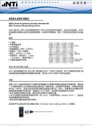
ApplicAtion note<br />
A <strong>PRACTICAL</strong> <strong>APPROACH</strong><br />
ON DIGILYZER DL1<br />
Digilyzer is the latest development in the Minstrument series.<br />
It is a comprehensive and complete digital analyzer that covers<br />
most measurements in the digital audio domain. Despite<br />
its amazing power it is battery operated and small enough to<br />
fit in the palm of your hand. The DL1 is a highly sophisticated<br />
stand alone digital audio analysis tool.<br />
This guide will give you a closer look at the advantages and<br />
functions of the DL1. The operation is very straightforward<br />
and intuitive (average familiarization time is less than two<br />
minutes). A minimal knowledge of digital audio is all that is<br />
required to operate the unit.<br />
Try it and see just how easy it is to get all the answers you<br />
need using the power of the Digilyzer DL1.<br />
10 good reasons to use the Digilyzer every day!<br />
1.<br />
2.<br />
3.<br />
4.<br />
5.<br />
6.<br />
7.<br />
8.<br />
9.<br />
Listen to the signal - With no signal there is not much to<br />
analyze.<br />
Correct wiring - More mistakes are made than you think.<br />
The engineers true audio rescue tool.<br />
Listen to ADAT signal - No extensive wiring to listen to the<br />
tape.<br />
Status analysis - a closed book?<br />
Panic! Five minutes to air.<br />
Why should I be interested in Bit statistics?<br />
Event logging - A measure to rectify all unexpected errors.<br />
How loud should broadcast material be? DL1 knows.<br />
10.<br />
Why do I need an oscilloscope?<br />
Jan 12, page 1 / 8
1. Listen to the signal - with no signal there is not much to analyze.<br />
DL1 Screenshot: Fast Access Setup<br />
www.nti-audio.com<br />
ApplicAtion note<br />
When it comes to digital audio one major drawback becomes obvious.<br />
Humans do not have digital ears and cannot listen to the incoming<br />
embedded audio signal. We can help! Simply connect an<br />
audio cable to the DL1 analyzer. Regardless of function selected,<br />
the digital signal is always converted to analog and fed to the internal<br />
loudspeaker and the stereo headphone output.<br />
Hot Key combinations (e.g. ESC + LEFT) allow fast and easy access<br />
to the most used settings like volume, audio muting and<br />
automatic gain control setting. No matter which measurement<br />
function is selected the „Fast Access Setup“ screen is displayed.<br />
Forgotten the key combinations? Just press ESC for one second<br />
and the screen, including a help for the shortcuts - is displayed.<br />
The built in automatic gain control (which can easily be enabled/<br />
disabled) adjusts the level to suit the speaker or headphone output.<br />
Its tremendous dynamic range of 140dB enables to hear even<br />
the smallest disturbance to the signal and even on silent lines<br />
dithering may be detected. No other tool of this size will detect<br />
and tell you the type of dithering within 10 seconds.<br />
If, by accident, an analog signal is connected to the DL1 it obviously<br />
will not provide any digital analysis but, and this is unique,<br />
it will make the signal audible by enabling an analog path to the<br />
internal speaker. This is a real boon when trying to identify cable<br />
connections.<br />
2. Correct wiring - more mistakes are made than you might think.<br />
DL1 Screenshot: Level Peak Screen<br />
Sounds familiar? You are called to a digital set up where you have<br />
no idea who wired what. As usual it is a mix of analog and digital<br />
equipment some of which is pro gear and some domestic. There<br />
are no informations or identifications. How long are the cables?<br />
How is the interface between AES3 and S/PDIF made?<br />
DL1 is the tool you need. Investigate and localize the problems.<br />
Connect the DL1 to a suspicious output or cable termination and<br />
you can look at the physical properties of the carrier signal. Regardless<br />
of what measurement function you have selected you<br />
will find displayed in the top left hand corner of the screen the<br />
physical properties of the carrier signal. Even in an unlocked mode<br />
the physical carrier level is measured. The level of the carrier is<br />
a good first guide to signal quality. The AES3 standard defines<br />
minimum signal acceptance which with reasonably short cables<br />
should be between 2V - 7Vpp. If there are impedance problems<br />
or longer cable runs the carrier level will drop to below 1V and the<br />
reliability is sacrificed.<br />
The DL1 checks the digital signal and the protocol to recognize<br />
page 2 / 8
DL1 Screenshot: Carrier Information<br />
3. The video engineer‘s true audio rescue tool.<br />
4. Listen to ADAT signals without special wiring.<br />
DL1 Screenshot: Channel Selection<br />
www.nti-audio.com<br />
ApplicAtion note<br />
errors. These errors can cause many audible effects and should<br />
ideally never occur. In case such an error occurs it is important to<br />
notice it and, for example, activate the “Event logger“ for further<br />
analysis.<br />
An error is indicated by filling the error indicator box black. When<br />
there is no error the filling of the box gets less until its white<br />
again (like a slow decay of a bar graph). In case such errors are<br />
indicated it would be necessary to follow the line and locate the<br />
mismatched format converter or impedance imbalance or indeed<br />
identify the overlong cable. You might be surprised at how often<br />
such mistakes occur.<br />
Be honest, most video engineers give little consideration to audio<br />
and in the process create format compatibility and synchronization<br />
problems. This, despite the fact that most signal degradation<br />
becomes audible before visible effects appear. There is even less<br />
understanding of digital audio in the video domain.<br />
That is why the Digilyzer becomes an irreplaceable aid to the<br />
video engineer. It effortlessly provides all the necessary information<br />
to complete the perfect job. The DL1 measures the sampling<br />
frequencies, formats, special status settings, audio content analysis<br />
and many more details. All this, in a handy, portable, inexpensive<br />
box.<br />
Try to listen to the individual tracks of an ADAT multi track recorder<br />
or even the new HD24 hard disc recorder without first connecting<br />
all the channels through your mixing console. It just isn‘t possible<br />
as the recorder has no headphones output. The DL1 makes it possible.<br />
Simply connect it to the 8 channel optical ADAT output and<br />
select which channel or channel pair is routed to the speaker or<br />
headphone out on your DL1.<br />
The Alesis 8 channel light pipe ADAT I + II interface is very widely<br />
used because of its ease of use and small connector size. This<br />
is especially so in semi pro/domestic applications and computer<br />
based hard disc recorders. The problem is that no measurement or<br />
monitoring equipment can directly handle the ADAT signals. DL1<br />
changes that. It can accept and process ADAT signals through its<br />
optical TOS link input. As with any other digital signal DL1 offers<br />
the converted ADAT signal at the speaker or headphone output.<br />
The channel selector allows to quickly toggle through the four<br />
available channel pairs with a single up/down key press.<br />
TASCAM TDIF signals can also be connected to the DL1 using a<br />
page 3 / 8
5. Status analysis - a closed book?<br />
DL1 Screenshot: Level Peak<br />
DL1 Screenshot: Channel Status<br />
DL1 Screenshot: Professional Format<br />
www.nti-audio.com<br />
ApplicAtion note<br />
commercially available TDIF/ADAT converter. The monitoring procedures<br />
are then identical to those outlined above.<br />
Most guides to the interpretation of digital audio channel status<br />
information starts with „...serial data is divided into 192 bit blocks<br />
lined up as bits, groups of bits, nibbles, bytes or words. Refer to<br />
the tables for interpretation.“ Make it easy for yourself. All you<br />
want is to get the essential data of the audio signal out of the<br />
bit stream. It is not important what the standard has reserved<br />
for future applications nor to which sub table you should refer to<br />
interpret the flags. The Digilyzer performs all this for you automatically.<br />
In all measurement functions DL1 will display the essential details<br />
of channel status which could affect the signal quality: The<br />
format, sampling frequency, resolution and the signal purpose. An<br />
consistency check is constantly running as a background task and<br />
will highlight any parameter that shows inconsistency with the<br />
physical parameters e.g. sampling frequency claims to be 44.1<br />
kHz but in reality is 32 kHz.<br />
As soon as the channel status analysis is selected DL1 will interpret<br />
the incoming bit sequence in accordance with AES3 and IEC<br />
60958 standards and display the results in blocks and groups. The<br />
display will also keep you informed of the carrier status, giving a<br />
feedback on what is connected and any error occurrence.<br />
Professional channel status<br />
Without even needing to understand the interpretation of channel<br />
status you can now, thanks to the DL1, e.g. questions like: What<br />
format is being transmitted? answer immediatelly: Professional<br />
without emphasis.<br />
Channel A and B have their own independent channel status, although<br />
in 99% of cases they will be the same. The DL1 Screenshot<br />
shows the display for channel A (indicated by “CH A“ on<br />
the top display line) and by quickly flying over the channel status<br />
screen it can be found that there is no difference between channels<br />
A and B. Otherwise the small square indicators in front of the<br />
changed label would turn into triangles and constantly toggle.<br />
On the second page, The DL1 Screenshot of the channel status<br />
screen a difference in the channel source and destination data of<br />
the two channels is indicated.<br />
The DL1 Screenshot also shows that the consistency check,<br />
indicates an inconsistency in word length by outlining the label<br />
page 4 / 8
DL1 Screenshot: Consumer Format page 1<br />
DL1 Screenshot: Consumer Format page 2<br />
6. Panic! Five minutes to air.<br />
www.nti-audio.com<br />
ApplicAtion note<br />
“WLEN 24 BIT“. It reports to have a 24 bit resolution but in reality<br />
there are less than 24 bits active. A quick switch over to bits<br />
statistics would indicate the details of the resolution of the operational<br />
converter. It is not easy to cheat the DL1‘s eyes!<br />
There is a great deal of channel status information being conveyed<br />
and so the DL1 is programmed to display it within two pages to<br />
make it easier to read and digest.<br />
If you need to see if the channel status is changing in respect to<br />
the current status simply store the current status by accessing<br />
“STO“. If any bit in the status is subsequently altered then the<br />
square flag in front of “RCL“ will turn into a triangle and toggle<br />
indicating a discrepancy. Pressing and releasing “RCL“will cause<br />
the screen indicator to toggle between the actual and recalled<br />
status allowing you to find the difference at a glance. This procedure<br />
can be applied to all pages of the status information.<br />
Consumer status<br />
Whenever a consumer status is embedded in the bit stream DL1<br />
automatically switches to transparent consumer format, again<br />
giving you all interpretation without the need for any tables.<br />
Any difference between channel A and channel B will be indicated<br />
by the square bullet signs turning to triangles and toggling. As<br />
well any deviation to the stored status will be shown in the bullet<br />
sign in front of “RCL“.<br />
The Digilyzer also interprets the fairly complex nested category<br />
tables providing simple device category statements such as “LA-<br />
SER OPTICAL PRODUCT“, “MINI DISC SYSTEM“, etc.. So the<br />
DL1 will even indicate whether the material is original or once<br />
only copied material.<br />
We have all been there! Five minutes to air and the main guest<br />
arrives with his small mini disc system and the request to record<br />
the interview. Given time there would be no problem but with<br />
only five minutes to go?<br />
The problem is that in the available digital environment is no analog<br />
output. You need to wire the minidisk into the digital bus output.<br />
No problem with DL1. Connect it into the digital output and<br />
then connect mini disc player to the DL1‘s headphone output.<br />
The Digilyzer is a full 24 bit 96 kHz D/A converter that meets the<br />
highest requirements of broadcast and live environments. A little<br />
word of warning: do not forget to disable the automatic gain control<br />
and activate a stereo function like vu ppm.<br />
page 5 / 8
7. Why should I be interested in Bit Statistics?<br />
DL1 Screenshot: Bit Statistics<br />
www.nti-audio.com<br />
It‘s best to prepare one of following cables:<br />
• 3.5mm stereo jack to 3.5mm stereo jack cable<br />
• 3.5mm stereo jack to 2x RCA<br />
• 3.5mm stereo jack to 2x XLR<br />
Because it saves time and money!<br />
ApplicAtion note<br />
Bit statistics provide a quick, easy to read, but detailed overview<br />
of the activity in the fairly complex serial bit stream of the two<br />
channels plus some important ancilliary information.<br />
Any bit remaining at 0 or 1 in each sample is represented on the<br />
screen accordingly. However if it is active and therefore changing<br />
it will be displayed on screen with an up/down arrow sign.<br />
The example screen shown on the left displays the expressions<br />
AUX and AUDIO DATA (to clarify the bit weighting the LSB and<br />
MSB position of the AUDIO DATA is marked). The two lines below<br />
these signs represent the 32 bit audio word for both channels.<br />
Since the MSB is on the right side the right bits always have to<br />
be active. After the active bits the remaining (inactive) bits have<br />
to be zero. We can easily count the arrows from right to left to<br />
find the actual word width or binary resolution. The DL1 will count<br />
these constantly for you and displays the measured resolution in<br />
the top left corner of the screen, e.g. 20 bit in our example DL1<br />
Screenshot.<br />
On the bottom line you will see displayed the ‚claimed‘ resolution.<br />
Other digital tools only provide the status information and not the<br />
measured resolution. The DL1 measures both so you can ensure<br />
that a device claiming to be 22 bit and priced accordingly actually<br />
delivers on its promises.<br />
Should you ever find steady 0 or 1 bits within the row of active bits<br />
you can assume that the transmitting audio codec is defective. In<br />
most cases hanging bits sound terrible but may, if they are close<br />
to the LSB, have only subtle audible effects. Investigations with<br />
the distortion function may enable rectification of the problems.<br />
The Digilyzer DL1 is the only palm top unit that performs these<br />
detailed measurements!<br />
page 6 / 8
8. Event logging - A measure to rectify all unexpected errors.<br />
DL1 Screenshot: Event Logger<br />
DL1 Screenshot: Logger Mask Screen<br />
www.nti-audio.com<br />
ApplicAtion note<br />
Intermittency is probably the most annoying thing we ever encounter.<br />
Things happen just when you don‘t need them but refuse<br />
to happen when you try and investigate the cause. Such<br />
problems are fairly prominent in broadcast where video and audio<br />
data streams are mixed together, hopefully synchronized. How<br />
can you measure the quality of this synchronization? Activate the<br />
event logger at the DL1 and sit back.<br />
As soon as the event logger is active it records any irregularity of<br />
the digital signal such as:<br />
• Unlock/lock carrier signal (e.g. physical disconnection)<br />
• Receiver confidence errors (e.g. poor carrier signal quality, eye<br />
pattern out of specs)<br />
• Parity errors (e.g. indicating a transmission error of at least one<br />
bit)<br />
• Change in the status information (e.g. change of source)<br />
• Invalid samples (e.g. conversion error of CD player)<br />
The DL1 event logger records many different events (not only the<br />
common ones like lock/unlock, parity error, ...). Things like changes<br />
of sample frequency, changes of carrier level, consistency check<br />
results, audio signal clipping and many more are required.<br />
To make navigation through such an enormous information flow<br />
simply to mechanism are included in DL1:<br />
• Events are „bundled“ in time clusters (intervals). These time<br />
intervals can be zoomed: zoom in to get more details, zoom<br />
out to get a better overview or to read out the events which<br />
occurred during the whole recording period. Using this facility<br />
you can use DL1 to listen to any CD or master and it will show<br />
you the number of errors of the CD. This is probably the best<br />
and most inexpensive way of ensuring that only top quality<br />
mastering or broadcast material is supplied.<br />
• If e.g. a parity error fills up your screen you simply can<br />
„mask“ this error from displaying. This mask is only active<br />
when you analyse the logged data - all events are recorded so<br />
you never miss one.<br />
Identifying even those slips in synchronizers which seldomly occur<br />
becomes an easy task to perform reliably.<br />
The DL1 provides sufficient log capacity to last for days or even<br />
weeks.<br />
page 7 / 8
9. How loud should broadcast material be? DL1 knows.<br />
DL1 Screenshot: vu + PPM display<br />
10. Why do I need an oscilloscope?<br />
DL1 Screenshot: Oscilloscope screen<br />
www.nti-audio.com<br />
ApplicAtion note<br />
Broadcast levels are limited to maximum output levels to ensure<br />
that transmission lines are not overloaded. The standard defines a<br />
maximum RMS level. This is no longer relevant in the digital age.<br />
What is now important is the maximum peak level which must<br />
never be exceeded to avoid audible distortion.<br />
Even though the maximum peak level is observed it is very noticeable<br />
when tuning through the radio stations that some channels<br />
appear louder than others. This is a result of compression of the<br />
signal, a trick, which is often used extensive to increase station<br />
identity awareness. The use of compression and other dynamic<br />
signal processing gives an apparent increase in loudness without<br />
exceeding the maximum peak level.<br />
DL1 features both a peak level meter (ppm) and a volume unit<br />
meter (vu) in parallel. The ppm will indicate the peak levels whilst<br />
the vu-meter will give a first approximation of the perceived loudness<br />
of the signal and as such reflects the grade of compression<br />
being used.<br />
Simply feed the broadcast signal into the DL1 and it will display,<br />
for both channels, the peak levels and also, as thickened bars, the<br />
vu levels. Max hold as well as the total max level are displayed in<br />
parallel. The closer the vu bar comes to the ppm level (centre bar)<br />
the higher the compression of the audio material.<br />
Have you ever been able to look at dither and listen to it at the<br />
same time? DL1 makes it reality.<br />
The DL1 scope is an ideal tool for educational purposes, helping<br />
to understand digital measurements and interpreting the results.<br />
The oscilloscope function can be used with any digital audio material.<br />
It will display the waveform of the signal in the automatic<br />
scaling display. The amazing dynamic range of the Y-scale gives<br />
results from 25% of the signal per division right down to 0.1ppm<br />
per division. This allows to even see the LSB of 24 bit audio material<br />
and look at the dithering.<br />
Check it out.<br />
page 8 / 8