Axial Piston Pump
Axial Piston Pump
Axial Piston Pump

You also want an ePaper? Increase the reach of your titles
YUMPU automatically turns print PDFs into web optimized ePapers that Google loves.
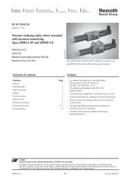
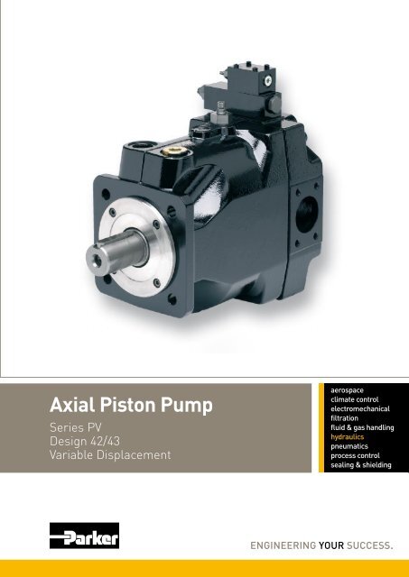
<strong>Axial</strong> <strong>Piston</strong> <strong>Pump</strong><br />
Series PV<br />
Design 42/43<br />
Variable Displacement
Catalogue HY30-3243/UK<br />
Contents<br />
<strong>Axial</strong> <strong>Piston</strong> <strong>Pump</strong><br />
Series PV<br />
Contents Page<br />
Introduction .....................................................................................................3<br />
Ordering Code Preferred Program .................................................................4<br />
Noise Levels ...................................................................................................8<br />
Efficiency and Case Drain Flows ....................................................................9<br />
Dimensions ...................................................................................................11<br />
Mounting kits ................................................................................................17<br />
<strong>Pump</strong> combinations<br />
Thru Drive, Shaft Load Limitations .....................................................18<br />
Compensators<br />
Compensators Dimensions ................................................................19<br />
Pressure Compensators ....................................................................23<br />
Load-Sensing Compensators.............................................................24<br />
Power Compensators .........................................................................25<br />
Power Compensators, Diagrams........................................................26<br />
Electronic Module PQDXXA (digital) ..................................................28<br />
General Installation Information .........................................................29<br />
Accessories Compensator .................................................................30<br />
2<br />
Parker Hannifin<br />
<strong>Pump</strong> and Motor Division<br />
Chemnitz, Germany
Catalogue HY30-3243/UK<br />
Introduction<br />
Technical Features<br />
• Low noise level<br />
• Fast response<br />
• Service-friendly<br />
• High self-priming speed<br />
• Compact design<br />
• Thru drive for 100% nominal torque<br />
Technical Data<br />
<strong>Axial</strong> <strong>Piston</strong> <strong>Pump</strong><br />
Series PV<br />
Size PV063 PV080 PV092 PV140 PV180 PV270<br />
Max. Displacement [cm3/rev.] 63 80 92 140 180 270<br />
Output flow at 1500 min-1 [l/min] 94.5 120 138 210 270 405<br />
Nominal pressure pN [bar] 350 350 350 350 350 350<br />
Max. pressure pmax 1) [bar] 420 420 420 420 420 420<br />
Max. Case drain pressure [bar] 0.5 0.5 0.5 0.5 0.5 0.5<br />
Min. Inlet pressure, abs. [bar] 0.8 0.8 0.8 0.8 0.8 0.8<br />
Max. Inlet pressure [bar] 16 16 16 16 16 16<br />
Input power at 1500 min-1 and 350 bar [kW] 61.5 78 89.5 136 175 263<br />
Max speed 2) [min -1 ] 2800 2500 2300 2400 2200 1800<br />
Moment of inertia [kgm 2 ] 0.018 0.018 0.018 0.030 0.030 0.098<br />
Weight [kg] 60 60 60 90 90 172<br />
1) Maximum 20% of the working cycle.<br />
2) The maximum speed ratings are shown for an inlet pressure of 1 bar (absolute) and for a fluid viscosity of<br />
ν= 30 mm 2 /s<br />
General Information<br />
Premium quality hydraulic mineral fluid are recommended,<br />
like HLP oils to DIN 51522, part 2, Brugger- value<br />
has to be 30 N/mm² minimum for general application<br />
and 50 N/mm² for heavily loaded hydraulic equipment<br />
and fast cycling machines and/or high dynamic loads,<br />
measured in accordance with DIN 51 347-2, see also<br />
Document HY30-3248/UK Parker Hydraulic- Fluids.<br />
Viscosity<br />
The normal operating viscosity should range between<br />
16 and 100 mm 2 /s (cSt). Max. start-up viscosity is<br />
800 mm 2 /s (cSt).<br />
Seals<br />
NBR seals are used for operation with hydraulic fluids<br />
based on mineral oil. For synthetic fluids, such as<br />
phosphoric acid esters, Flourocarbon seal are required.<br />
3<br />
With thru drive for single and multiple pumps<br />
Swash plate type for open circuit<br />
Filtration<br />
For maximum pump and system component functionability<br />
and life, the system should be protected from<br />
contamination by effective filtration.<br />
Fluid cleanliness should be in accordance with ISO<br />
classification ISO 4406:1999. The quality of filter elements<br />
should be in accordance with ISO standards.<br />
Minimum requirement for filtration rate x (mm);<br />
General hydraulic systems for satisfactory operation:<br />
Class 20/18/15, according to ISO 4406:1999<br />
Hydraulic systems with maximised component life and<br />
functionability:<br />
Class 18/16/13, according to ISO 4406:1999<br />
Parker Hannifin<br />
<strong>Pump</strong> and Motor Division<br />
Chemnitz, Germany
Catalogue HY30-3243/UK<br />
Ordering Code Preferred Program<br />
<strong>Axial</strong> piston<br />
pump<br />
variable<br />
displacement<br />
high<br />
pressure<br />
version<br />
Code Rotation 1)<br />
R Clockwise<br />
1) When looked on shaft<br />
Size<br />
and<br />
displacement<br />
<strong>Axial</strong> <strong>Piston</strong> <strong>Pump</strong><br />
Series PV<br />
P V R 1 K 1 T 1 N<br />
Code Displacement Size<br />
063 63 cm³/rev 3<br />
080 80 cm³/rev 3<br />
092 92 cm³/rev 3<br />
140 140 cm³/rev 4<br />
180 180 cm³/rev 4<br />
270 270 cm³/rev 5<br />
Rotation<br />
Code Mounting interface Shaft<br />
K metr. ISO 4-hole flange Cylindric, key<br />
L 3019/2 4-hole flange Splined, DIN 5480<br />
Code Port 2) Threads 3)<br />
1 BSPP Metric<br />
4 4) BSPP Metr. M14<br />
<strong>Pump</strong> Compensator<br />
Standard Threads 2nd<br />
Compensator<br />
Design<br />
pump<br />
series:<br />
(not required<br />
for order)<br />
Mounting<br />
code Thru drive<br />
2) Drain, gauge and flushing ports<br />
3) All mounting and connecting threads<br />
4) For PV063-PV180 only: pressure port 1 1/4” with 4 x M14 instead of 4 x M12<br />
4<br />
Seals<br />
Mounting kits for flexible mounting of multiple pumps, see page 17.<br />
see opposite page<br />
Code Seals<br />
N NBR<br />
Code 2nd pump option 5)<br />
1 Single pump, no 2nd pump<br />
and coupling<br />
Code Thru drive option<br />
no adaptor for 2nd pump<br />
T Single pump<br />
prepared for thru drive<br />
Parker Hannifin<br />
<strong>Pump</strong> and Motor Division<br />
Chemnitz, Germany
Catalogue HY30-3243/UK<br />
Ordering Code Preferred Program<br />
Standard Pressure Compensator<br />
Code Compensator options<br />
0 0 1 Without compensator<br />
F D S 10 - 140 bar, spindle + lock nut<br />
F H S 40 - 210 bar, spindle + lock nut<br />
F W S 70 - 350 bar, spindle + lock nut<br />
Remote Compensator options<br />
F R Remote pressure compensator<br />
F F Load-Sensing compensator<br />
Variations for Remote Compensator<br />
C External pressure pilot 8)<br />
1 NG6/D03 interface top side<br />
P Pilot valve PVAC1P* mounted<br />
Power compensator<br />
Code Displacement Compensator option<br />
063 140 180 270 Nom. power [kW] Nom. torque-<br />
092 at 1500 min -1 [Nm]<br />
G 11 71<br />
H 15 97<br />
K 18.5 120<br />
M 22 142<br />
S 30 195<br />
T 37 240<br />
U 45 290<br />
W 55 355<br />
Y 75 485<br />
Z 90 585<br />
2 110 715<br />
3 132 850<br />
Function<br />
L Power compensator<br />
C Power compensator<br />
and load-sensing<br />
Variation<br />
A NG6 interface top side<br />
B No pressure compensation<br />
C Adjustable<br />
pressure compensation<br />
Code Compensator style<br />
electro hydraulic control<br />
F P V closed loop displacement control only, no<br />
pressure compensation<br />
U P closed loop proportional displacement<br />
control with pressure compensation<br />
compensator version<br />
R balanced pressure control, NG6 interface<br />
K version UPR, with proportional pilot valve<br />
type PVACRE..35 mounted<br />
M version UPK, with pressure sensor for<br />
closed loop pressure and power control<br />
<strong>Axial</strong> <strong>Piston</strong> <strong>Pump</strong><br />
Series PV<br />
5<br />
Note:<br />
Compensator differential ∆p is factory pre-set to:<br />
remote compensators, power control 15 ± 1 bar<br />
load sensing comp. (not power control) 10 ± 1 bar<br />
Parker Hannifin<br />
<strong>Pump</strong> and Motor Division<br />
Chemnitz, Germany
Catalogue HY30-3243/UK<br />
Ordering Code Options on Request<br />
P V<br />
axial piston<br />
pump<br />
variable<br />
displacement<br />
high<br />
pressure<br />
version<br />
Code Displacement Size<br />
063 63 cm³/rev 3<br />
080 80 cm³/rev 3<br />
092 92 cm³/rev 3<br />
140 140 cm³/rev 4<br />
180 180 cm³/rev 4<br />
270 270 cm³/rev 5<br />
Code Rotation 1)<br />
R Clockwise<br />
L Counter clockwise<br />
1) When looked on shaft<br />
Code Variation<br />
1 Standard<br />
9 special<br />
adjustment 2)<br />
2) requires Kxxxx number<br />
size<br />
and<br />
displacement<br />
Code Mounting interface Shaft<br />
D<br />
E<br />
F<br />
4-hole flange<br />
4-hole flange<br />
Cylindric, key<br />
Splined, SAE<br />
3) G<br />
4-hole flange Cylindric, key<br />
3) SAE<br />
ISO<br />
3019/1<br />
4-hole flange Splined, SAE<br />
K metr. ISO 4-hole flange Cylindric, key<br />
L 3019/2 4-hole flange Splined, DIN 5480<br />
3) Codes F and G only for PV140/180<br />
Code Port 4) Threads 5)<br />
1 BSPP metric<br />
3 UNF UNC<br />
4 6) BSPP metr. M14<br />
7 ISO 6149 UNC<br />
8 ISO 6149 metrisch<br />
4) Drain, gauge and flushing ports<br />
5) All mounting and connecting threads<br />
6) For PV063, PV080-PV180 only: pressure port 1 1/4”<br />
with 4 x M14 instead of 4 x M12<br />
<strong>Axial</strong> <strong>Piston</strong> <strong>Pump</strong><br />
Series PV<br />
R 1 1 N 1 K T<br />
compensator<br />
rotation<br />
Mounting kits for flexible mounting of<br />
multiple pumps, see page 17.<br />
mounting<br />
interface<br />
variation threads<br />
code<br />
thru drive<br />
code<br />
6<br />
coupling<br />
code<br />
seals<br />
Code Coupling for thru drive<br />
1 Single pump, no coupling<br />
2 PV140 or PV180 mounted<br />
3 PV pump mounted<br />
4 Gear pump mounted<br />
Code Thru drive option<br />
No adaptor for 2nd pump<br />
T Single pump prepared<br />
for thru drive<br />
Code Seals<br />
N NBR<br />
V FPM<br />
W NBR with PTFE shaft seal<br />
P FPM with PTFE shaft seal<br />
with adaptor for 2nd pump as single part 10)<br />
A SAE A, Ø 82.55 mm MK-PVBGxAMN<br />
B SAE B, Ø 101.6 mm MK-PVBGxBMN<br />
C7) SAE C, Ø 127 mm MK-PVBGxCMN<br />
D7) SAE D, Ø 152,4 mm MK-PVBGxDMN<br />
E8) SAE E, Ø 165,1 mm MK-PVBGxEMN<br />
G9) metric, Ø 63 mm MK-PVBGxGMN<br />
H metric, Ø 80 mm MK-PVBGxHMN<br />
J metric, Ø 100 mm MK-PVBGxJMN<br />
K7) metric, Ø 125 mm MK-PVBGxKMN<br />
L7) metric, Ø 160 mm MK-PVBGxLMN<br />
M8) metric, Ø 200 mm MK-PVBGxMMN<br />
See dimensions for details<br />
7) only for PV063 and larger<br />
8) only for PV270<br />
9) only for PV063 - PV092<br />
10) x= frame size, see page 17.<br />
see next page<br />
Option 2, 3 and 4 not available for single pump. Second pump<br />
must be specified with full model code.<br />
Parker Hannifin<br />
<strong>Pump</strong> and Motor Division<br />
Chemnitz, Germany
Catalogue HY30-3243/UK<br />
Ordering Code Options on Request<br />
Code<br />
Standard Pressure Compensator<br />
Compensator options<br />
0 0 1 No compensator<br />
1 0 0 With cover plate, no control function<br />
F D S 10 - 140 bar, Spindle + lock nut<br />
F H S 40 - 210 bar, Spindle + lock nut<br />
F W S 70 - 350 bar, Spindle + lock nut<br />
Remote compensator options<br />
F R Remote pressure compensator<br />
F S Variation R, for quick unload valve<br />
F F Load-Sensing compensator<br />
F T Two valve load-sensing compensator<br />
Compensator variation<br />
C External pressure pilot 14)<br />
1 NG6 interface top side for pilot valves<br />
2 Like 1 but with ext. pilot port16) P Pilot valve PVAC1P* mounted<br />
K Prop.-pilot valve type PVACRE..35 mounted<br />
L Pilot valve with DIN lock mounted<br />
Z Accessory mounted 15)<br />
Horse power compensator<br />
Code Displacement Compensator option<br />
063 140 180 270 Nominal HP. [kW] Nom. torque<br />
100 at 1500 rpm [Nm]<br />
G 11 71<br />
H 15 97<br />
K 18,5 120<br />
M 22 142<br />
S 30 195<br />
T 37 240<br />
U 45 290<br />
W 55 355<br />
Y 75 485<br />
Z 90 585<br />
2 110 715<br />
3 132 850<br />
Function<br />
L Horse power compensator<br />
C Horse power compensator<br />
and Load Sensing<br />
Compensator variation<br />
A NG 6 interface top side<br />
B No pressure compensation<br />
C Adjustable pressure compensation<br />
K Prop.-pilot valve<br />
type PVACRE..35 mounted<br />
Z Accessories mounted 15)<br />
<strong>Axial</strong> <strong>Piston</strong> <strong>Pump</strong><br />
Series PV<br />
7<br />
Electrohydraulic compensator<br />
Code Compensator option<br />
Pilot pressure supply<br />
F P V closed loop displacement control only,<br />
no pressure compensation<br />
Function<br />
U P Proportionalhubvolumenregelung<br />
Variation<br />
R balanced pressure control, NG6 interface<br />
K version UPR, with proportional pilot valve<br />
type PVACRE..35 mounted<br />
M version UPK, with pressure sensor for<br />
closed loop pressure and power control<br />
Z Version R, accessories mounted 15)<br />
Note<br />
Compensator differential ∆p is to be adjusted:<br />
remote compensators, power control 15 ± 1 bar<br />
(Codes FR*, FT*, *L*, *C*, UPR, UPD, UPZ, UPG)<br />
load sensing comp. (not power control) 10 ± 1 bar<br />
(Codes FF*)<br />
14) Not for two-valve-compensator<br />
15) Accessories not included, please specify on<br />
order with full model code.<br />
16) Only Codes *FR* and *FT*<br />
Parker Hannifin<br />
<strong>Pump</strong> and Motor Division<br />
Chemnitz, Germany
Catalogue HY30-3243/UK<br />
Noise Levels<br />
PV063 - PV092<br />
Noise level [dB(A)]<br />
PV140<br />
Noise level [dB(A)]<br />
70<br />
60<br />
52<br />
0 100 200 300<br />
Pressure [bar]<br />
80<br />
70<br />
at full flow<br />
at full flow<br />
at deadhead<br />
at deadhead<br />
<strong>Axial</strong> <strong>Piston</strong> <strong>Pump</strong><br />
Series PV<br />
8<br />
PV180<br />
PV270<br />
60<br />
0 100 200 300<br />
60<br />
0 100 200 300<br />
Pressure [bar] Pressure [bar]<br />
Typical sound level for single pumps, measured in unechoic chamber<br />
according to DIN 45 635, part 1 and 26. Microphone distance 1m;<br />
speed: n = 1500 rpm.<br />
Noise level [dB(A)]<br />
Noise level [dB(A)]<br />
80<br />
70<br />
60<br />
0 100 200 300<br />
Pressure [bar]<br />
80<br />
70<br />
at full flow<br />
at full flow<br />
at deadhead<br />
at deadhead<br />
All data measured with mineral oil viscosity 30 mm²/s (cSt) at 50°C.<br />
Parker Hannifin<br />
<strong>Pump</strong> and Motor Division<br />
Chemnitz, Germany
Catalogue HY30-3243/UK<br />
Efficiency and Case Drain Flows<br />
Efficiency, power consumption<br />
PV063<br />
Output flow [l/min]<br />
100<br />
80<br />
60<br />
40<br />
20<br />
0<br />
PV080<br />
Output flow [l/min]<br />
120<br />
96<br />
72<br />
48<br />
24<br />
0<br />
PV092<br />
Output flow [l/min]<br />
150<br />
120<br />
90<br />
60<br />
30<br />
0<br />
Input power [kW]<br />
Input power [kW]<br />
Input power [kW]<br />
70<br />
56<br />
42<br />
28<br />
14<br />
0<br />
0 100 200 300<br />
Pressure [bar]<br />
80<br />
64<br />
48<br />
32<br />
16<br />
0<br />
0 100 200 300<br />
Pressure [bar]<br />
100<br />
80<br />
60<br />
40<br />
20<br />
output flow<br />
vol. efficiency<br />
overall efficiency<br />
input power at full flow<br />
input power at deadhead<br />
output flow, vol. efficiency<br />
output flow<br />
overall efficiency<br />
input power at full flow<br />
input power at deadhead<br />
vol. efficiency<br />
overall efficiency<br />
input power at full flow<br />
input power at deadhead<br />
0<br />
0 100 200 300<br />
Pressure [bar]<br />
100<br />
80<br />
60<br />
40<br />
20<br />
0<br />
100<br />
80<br />
60<br />
40<br />
20<br />
0<br />
100<br />
80<br />
60<br />
40<br />
20<br />
0<br />
Efficiency [%] (overall, volymetric)<br />
Efficiency [%] (overall, volymetric)<br />
Efficiency [%] (overall, volymetric)<br />
<strong>Axial</strong> <strong>Piston</strong> <strong>Pump</strong><br />
Series PV<br />
9<br />
Efficiency and case drain flows PV063, PV080, PV092<br />
The efficiency and power graphs are measured at an<br />
input speed of n = 1500 rpm, a temperature of 50 °C and<br />
a fluid viscosity of 30 mm2 /s.<br />
Case drain flow and compensator control flow leave via<br />
the drain port of the pump. To the values shown are to be<br />
added 1 to 1.2 l/min , if at pilot operated compensators<br />
(codes FR*, FF*, FT*, power compensator and p-Q-control)<br />
the control flow of the pressure pilot valve also goes<br />
through the pump.<br />
Please note: The values shown below are only valid for<br />
static operation. Under dynamic conditions and at rapid<br />
compensation of the pump the volume displaced by the<br />
servo piston also leaves the case drain port. This dynamic<br />
control flow can reach up to 80 l/min! Therefore the case<br />
drain line is to lead to the reservoir at full size and without<br />
restrictions as short and direct as possible.<br />
Case drain flows PV063-092<br />
Drain flow [l/min]<br />
12<br />
8<br />
4<br />
dead head<br />
full flow<br />
0<br />
0 100 200 300<br />
Pressure [bar]<br />
Parker Hannifin<br />
<strong>Pump</strong> and Motor Division<br />
Chemnitz, Germany
Catalogue HY30-3243/UK<br />
Efficiency and Case Drain Flows<br />
Efficiency, power consumption<br />
PV140<br />
Output flow [l/min]<br />
250<br />
200<br />
150<br />
100<br />
50<br />
0<br />
PV180<br />
Output flow [l/min]<br />
300<br />
240<br />
180<br />
120<br />
60<br />
0<br />
PV270<br />
Output flow [l/min]<br />
500<br />
400<br />
300<br />
200<br />
100<br />
0<br />
Input power [kW]<br />
Input power [kW]<br />
Input power [kW]<br />
150<br />
120<br />
90<br />
60<br />
30<br />
175<br />
140<br />
105<br />
0<br />
0 100 200 300<br />
Pressure [bar]<br />
70<br />
35<br />
250<br />
200<br />
150<br />
100<br />
0<br />
0 100 200 300<br />
Pressure [bar]<br />
50<br />
vol. efficiency<br />
vol. efficiency<br />
overall efficiency<br />
vol. efficiency<br />
overall efficiency<br />
output flow<br />
input power at full flow<br />
input power at deadhead<br />
output flow<br />
input power at full flow<br />
input power at deadhead<br />
overall efficiency<br />
output flow<br />
input power at full flow<br />
input power at deadhead<br />
0<br />
0 100 200 300<br />
Pressure [bar]<br />
100<br />
80<br />
60<br />
40<br />
20<br />
0<br />
100<br />
80<br />
60<br />
40<br />
20<br />
0<br />
100<br />
80<br />
60<br />
40<br />
20<br />
Efficiency [%] (overall, volymetric)<br />
Efficiency [%] (overall, volymetric)<br />
0<br />
Efficiency [%] (overall, volymetric)<br />
<strong>Axial</strong> <strong>Piston</strong> <strong>Pump</strong><br />
Series PV<br />
10<br />
Efficiency and case drain flows PV140, PV180, PV270<br />
The efficiency and power graphs are measured at an<br />
input speed of n = 1500 rpm, a temperature of 50 °C and<br />
a fluid viscosity of 30 mm2 /s.<br />
Case drain flow and compensator control flow leave via<br />
the drain port of the pump. To the values shown are to be<br />
added 1 to 1.2 l/min , if at pilot operated compensators<br />
(codes FR*, FF*, FT*, power compensator and p-Q-control)<br />
the control flow of the pressure pilot valve also goes<br />
through the pump.<br />
Please note: The values shown below are only valid for<br />
static operation. Under dynamic conditions and at rapid<br />
compensation of the pump the volume displaced by the<br />
servo piston also leaves the case drain port. This dynamic<br />
control flow can reach up to 120 l/min! Therefore the case<br />
drain line is to lead to the reservoir at full size and without<br />
restrictions as short and direct as possible.<br />
Case drain flows PV140-180<br />
Drain flow [l/min]<br />
18<br />
12<br />
6<br />
0<br />
0 100 200 300<br />
Pressure [bar]<br />
Case drain flows PV270<br />
Drain flow [l/min]<br />
24<br />
16<br />
8<br />
dead head<br />
dead head<br />
full flow<br />
full flow<br />
0<br />
0 100 200 300<br />
Pressure [bar]<br />
Parker Hannifin<br />
<strong>Pump</strong> and Motor Division<br />
Chemnitz, Germany
Catalogue HY30-3243/UK<br />
Dimensions<br />
PV063 - 092, metric version<br />
mounting hole for<br />
horse power compensator pilot<br />
or displacement feedback LVDT<br />
78<br />
86 238<br />
26<br />
77.8<br />
66.6<br />
50<br />
252<br />
31<br />
31<br />
drain port L1,<br />
dimensions see L2<br />
20<br />
9<br />
287<br />
max. 308<br />
gage port M; G1/4<br />
43.5 92<br />
optional M12x1.5; ISO 6149-1<br />
(thread options 7 and 8)<br />
or 7/16-20 UNF (thread option 3)<br />
inlet:<br />
flage acc. ISO 6162<br />
DN51; PN200<br />
4xM12, 20 deep<br />
optional 1/2-13UNC-2B<br />
(thread options 3 and 7)<br />
4xM12, 20 deep<br />
optional 1/2-13 UNC-2B<br />
(thread options 3 and 7)<br />
or thread option 4<br />
(M14, 20 deep)<br />
32<br />
outlet:<br />
flage acc. ISO 6162<br />
DN32; PN400<br />
drain port L2; G3/4<br />
optional M27x2; ISO 6149-1<br />
(thread options 7 and 8)<br />
or 1 1/16-12 UNF<br />
(thread option 3)<br />
121<br />
Ø40 k6<br />
43 -0.25<br />
<strong>Axial</strong> <strong>Piston</strong> <strong>Pump</strong><br />
Series PV<br />
9<br />
10<br />
56<br />
11<br />
196<br />
h8 Ø160<br />
key 12x8x80<br />
DIN 6885<br />
Shown is a clockwise rotating pump with standard pressure compensator.<br />
Counter clockwise rotating pumps have inlet, outlet and gauge port reversed.<br />
192 36<br />
Ø160 h8<br />
181<br />
120<br />
thread M12,<br />
28 deep<br />
135<br />
flushing port L3; G1/2<br />
optional M27x2; ISO 6149-1<br />
(thread options 7 and 8)<br />
or 1 1/16-12 UNF<br />
(thread option 3)<br />
200<br />
view X<br />
200<br />
max. 133<br />
The pump shown above has mounting option K<br />
and thru drive option T (prepared for thru drive)<br />
Mounting optional L<br />
splined shaft W40x1.5x15x8f<br />
DIN 5480<br />
18<br />
Parker Hannifin<br />
<strong>Pump</strong> and Motor Division<br />
Chemnitz, Germany
Catalogue HY30-3243/UK<br />
Dimensions<br />
PV063 - 092, SAE version<br />
Shown above is<br />
Mounting option D<br />
Variation with thru drive<br />
287<br />
L<br />
<strong>Axial</strong> <strong>Piston</strong> <strong>Pump</strong><br />
Series PV<br />
Key:<br />
11,11 x 11,11<br />
80 long<br />
K<br />
12<br />
B<br />
Thread:<br />
1/2-13UNC-2B<br />
28 deep<br />
Mounting option E<br />
Splined shaft 13T-8/16 DP,<br />
ANSI B92.1<br />
drive output: splined shaft<br />
W32x1.5x20x8f DIN5480<br />
Thru drive adaptors are available with the following dimensions<br />
Drawing Dimension<br />
A B C D E F G Remark<br />
Thru drive option<br />
A 82,55 10 - - - 100 M8 SAE A 2-Bolt<br />
B 101,6 12 127 89,8 M12 146 M12 SAE B 2/4-Bolt<br />
C 127 14 161,6 114,5 M12 181 M16 SAE C 2/4-Bolt<br />
D 152,4 14 228,5 161,6 M16 - - SAE D 4-Bolt<br />
G 63 10 85 60,1 M8 100 M8 2/4-Bolt<br />
H 80 10 103 72,8 M8 109 M10 2/4-Bolt<br />
J 100 12 125 88,4 M10 140 M12 2/4-Bolt<br />
K 125 12 160 113,1 M12 180 M16 2/4-Bolt<br />
L 160 12 200 141,4 M16 - - 4-Bolt<br />
H<br />
A<br />
D<br />
F<br />
C<br />
E<br />
G<br />
Parker Hannifin<br />
<strong>Pump</strong> and Motor Division<br />
Chemnitz, Germany
Catalogue HY30-3243/UK<br />
Dimensions<br />
PV140 - 180, metric version<br />
106<br />
X<br />
88.9<br />
66.6<br />
mounting hole for<br />
horse power compensator<br />
pilot or LVDT for<br />
displacement feedback<br />
50.8<br />
31.8<br />
105<br />
283<br />
35<br />
35<br />
drain port L1,<br />
dimensions see L2<br />
max. 385<br />
350<br />
4xM12, 20 deep<br />
optional 1/2-13 UNC-2B<br />
(thread options 3 and 7)<br />
or thread option 4<br />
(M14, 22 deep)<br />
32<br />
outlet:<br />
flage acc. ISO 6162<br />
DN32; PN400<br />
20<br />
48<br />
gage port M; G1/4<br />
optional M12x1.5; ISO 6149-1<br />
(thread options 7 and 8)<br />
or 7/16-20 UNF (thread option 3)<br />
147<br />
9<br />
92<br />
78<br />
<strong>Axial</strong> <strong>Piston</strong> <strong>Pump</strong><br />
Series PV<br />
drain port L2; G1<br />
optional M33x2; ISO 6149-1<br />
(thread options 7 and 8)<br />
or 1 5/16-12 UNF<br />
204<br />
(thread option 3)<br />
Ø 50k6 Ø 160h8 53.5-0.25<br />
13<br />
200<br />
9<br />
10<br />
thread M16,<br />
36 deep<br />
key 14x9x75<br />
DIN 6885<br />
158<br />
145<br />
Ø 160h8<br />
Mounting optional L<br />
splined shaft W50x2x24x9g<br />
DIN 5480<br />
200<br />
view X<br />
200<br />
max. 133<br />
233<br />
40<br />
pressure port: 295<br />
flushing port L3; G3/4<br />
suction port: 305<br />
optional M27x2; ISO 6149-1<br />
inlet:<br />
(thread options 7 and 8)<br />
flage acc. ISO 6162<br />
or 1 1/16-12 UNF<br />
DN64; PN160<br />
(thread option 3)<br />
The pump shown above has mounting option K<br />
64<br />
and thru drive option T (prepared for thru drive)<br />
4xM12, 20 deep<br />
optional 1/2-13UNC-2B<br />
(thread options 3 and 7)<br />
Shown is a clockwise rotating pump with standard pressure compensator.<br />
Counter clockwise rotating pumps have inlet, outlet and gauge port reversed.<br />
18<br />
Parker Hannifin<br />
<strong>Pump</strong> and Motor Division<br />
Chemnitz, Germany
Catalogue HY30-3243/UK<br />
Dimensions<br />
PV140 - 180, SAE version<br />
Variation with thru drive<br />
Shown above is mounting option D<br />
415<br />
350<br />
<strong>Axial</strong> <strong>Piston</strong> <strong>Pump</strong><br />
Series PV<br />
Thru drive adaptors are available with the following dimensions<br />
Drawing Dimension<br />
Mounting option E<br />
Splined shaft 15T-8/16 DP,<br />
flat root, side fit<br />
ANSI B92.1<br />
Mounting option F<br />
97<br />
14<br />
B<br />
Thread:<br />
5/8-11UNC-2B<br />
25 deep<br />
Key:<br />
12.7 x 12.7<br />
75 long<br />
Key:<br />
11.11 x 11.11<br />
55 long<br />
Thread:<br />
1/2-13UNC-2B<br />
25 deep<br />
drive output: splined shaft<br />
W40x1.5x25x8f DIN5480<br />
Thru drive option<br />
A 82,55 10 - - - 106 M10 SAE A 2-Bolt<br />
B 101,6 12 127 89,8 M12 146 M12 SAE B 2/4-Bolt<br />
C 127 14 161,6 114,5 M12 181 M16 SAE C 2/4-Bolt<br />
D 152,4 14 228,5 161,6 M16 - - SAE D 4-Bolt<br />
A<br />
H<br />
A B C D E F G Remark<br />
H 80 10 103 72,8 M8 109 M10 2/4-Bolt<br />
J 100 12 125 88,4 M10 140 M12 2/4-Bolt<br />
K 125 12 160 113,1 M12 180 M16 2/4-Bolt<br />
L 160 12 200 141,4 M16 - - 4-Bolt<br />
F<br />
Mounting option G<br />
Splined shaft 13T-8/16 DP,<br />
flat root, side fit<br />
ANSI B92.1<br />
D<br />
C<br />
E<br />
G<br />
Parker Hannifin<br />
<strong>Pump</strong> and Motor Division<br />
Chemnitz, Germany
Catalogue HY30-3243/UK<br />
Dimensions<br />
PV 270, metric version<br />
128<br />
110<br />
120.7<br />
79.4<br />
mounting hole for<br />
horse power compensator<br />
pilot or LVDT for<br />
displacement feedback<br />
69.8<br />
36.5<br />
drain port L1,<br />
dimensions see L2<br />
472.5<br />
max. 510<br />
Ø88<br />
Ø38<br />
403<br />
378<br />
45<br />
45<br />
306<br />
<strong>Axial</strong> <strong>Piston</strong> <strong>Pump</strong><br />
Series PV<br />
drain port L2; G1 1/4<br />
optional M42x2; ISO 6149-1<br />
(thread options 7 and 8)<br />
or 1 5/8-12 UNF<br />
(thread option 3)<br />
15<br />
9<br />
115<br />
gage port M; G1/4<br />
optional M12x1.5; ISO 6149-1 (thread options 7 and 8)<br />
or 7/16-20 UNF (thread option 3)<br />
inlet:<br />
flage acc. ISO 6162<br />
DN89; PN25<br />
4xM16, 32 deep<br />
optional 5/8-11 UNC-2B<br />
(thread options 3 and 7)<br />
4xM16, 32 deep<br />
optional 5/8-11 UNC-2B<br />
(thread options 3 and 7)<br />
outlet:<br />
flage acc. ISO 6162<br />
DN38; PN400<br />
Shown is a clockwise rotating pump with standard pressure compensator.<br />
Counter clockwise rotating pumps have inlet, outlet and gauge port reversed.<br />
60<br />
25<br />
172<br />
Ø65 Ø200<br />
k6 h8<br />
80<br />
69 -0.25<br />
Ø200 h8<br />
9<br />
10<br />
key 18x11x98<br />
DIN 6885<br />
230<br />
thread M20,<br />
42 deep<br />
184<br />
176<br />
22<br />
265<br />
max. 133<br />
250<br />
view X<br />
50<br />
250<br />
flushing port L3; G3/4<br />
optional M27x2; ISO 6149-1<br />
(thread options 7 and 8)<br />
or 1 1/16-12 UNF<br />
(thread option 3)<br />
The pump shown above has mounting option K<br />
and thru drive option T (prepared for thru drive)<br />
Mounting optional L<br />
splined shaft W60x2x28x9g<br />
DIN 5480<br />
Parker Hannifin<br />
<strong>Pump</strong> and Motor Division<br />
Chemnitz, Germany
Catalogue HY30-3243/UK<br />
Dimensions<br />
PV270, SAE version<br />
Variation with thru drive<br />
Shown above is mounting option D<br />
472.5<br />
531.5<br />
<strong>Axial</strong> <strong>Piston</strong> <strong>Pump</strong><br />
Series PV<br />
Thru drive adaptors are available with the following dimensions<br />
Drawing Dimension<br />
88<br />
Thru drive option<br />
A 82,55 8 - - - 106 M10 SAE A 2-Bolt<br />
B 101,6 11 127 89,8 M12 146 M12 SAE B 2/4-Bolt<br />
C 127 13,5 161,6 114,5 M12 181 M16 SAE C 2/4-Bolt<br />
D 152,4 13,5 228,5 161,6 M16 229 M20 SAE D 2/4-Bolt<br />
E 165,1 17 317,5 224,5 M20 - - SAE E 4-Bolt<br />
H 80 8,5 103 72,8 M8 109 M10 2/4-Bolt<br />
J 100 10,5 125 88,4 M10 140 M12 2/4-Bolt<br />
K 125 10,5 160 113,1 M12 180 M16 2/4-Bolt<br />
L 160 13,5 200 141,4 M16 224 M20 2/4-Bolt<br />
M 200 13,5 250 176,8 M20 - - 4-Bolt<br />
16<br />
Key:<br />
12.7 x 12.7<br />
75 long<br />
Ø50.8 -0.05<br />
56.4 ±0.13<br />
15.9<br />
8<br />
89.5<br />
97.5<br />
Ø165.1-0.05<br />
Mounting option E<br />
Splined shaft 15T-8/16 DP,<br />
flat root, side fit<br />
ANSI B92.1<br />
97<br />
Ø165.1-0.05<br />
Thread:<br />
5/8-11UNC-2B<br />
25 deep<br />
drive output: splined shaft<br />
W50x2x24x9g DIN5480<br />
A B C D E F G Remark<br />
B<br />
H<br />
A<br />
112.25<br />
224.5<br />
D F<br />
C<br />
E<br />
Parker Hannifin<br />
<strong>Pump</strong> and Motor Division<br />
Chemnitz, Germany<br />
20.6<br />
224.5<br />
112.25<br />
G
Catalogue HY30-3243/UK<br />
Kits<br />
Mounting kits for multiple pumps, for second pump option<br />
Code <strong>Pump</strong> size<br />
69<br />
MK<br />
Mounting<br />
kit<br />
1 <strong>Pump</strong> size 1: PV016 - PV023<br />
2 <strong>Pump</strong> size 2: PV032 - PV046<br />
3 <strong>Pump</strong> size 3: PV063 - PV092<br />
4 <strong>Pump</strong> size 4: PV140 - PV180<br />
5 <strong>Pump</strong> size 5: PV270<br />
Kit contains positions 30, 69, 84,<br />
85 and 87, see drawing below.<br />
front pump<br />
30 84<br />
PV<br />
<strong>Axial</strong><br />
piston<br />
pump<br />
series PV<br />
85 87<br />
91<br />
BG<br />
Mounting kits for multiple pumps, couplings<br />
Code <strong>Pump</strong> size<br />
1 <strong>Pump</strong> size 1: PV016 - PV023<br />
2 <strong>Pump</strong> size 2: PV032 - PV046<br />
3 <strong>Pump</strong> size 3: PV063 - PV092<br />
4 <strong>Pump</strong> size 4: PV140 - PV180<br />
5 <strong>Pump</strong> size 5: PV270<br />
Kit contains positions 91 (and 92 for<br />
keyed shaft).<br />
MK<br />
Mounting<br />
kit<br />
Size<br />
Code Second pump, SAE<br />
<strong>Axial</strong> <strong>Piston</strong> <strong>Pump</strong><br />
Series PV<br />
Second pump Thread<br />
T Prepared for thru drive option (plugged)<br />
Y SAE AA, diameter 50.8 mm<br />
A SAE A, diameter 82.55 mm<br />
B SAE B, diameter 101.6 mm<br />
C SAE C, diameter 127,mm<br />
D SAE D, diameter 152.4 mm<br />
E SAE E, diameter 165.1 mm<br />
Second pump, metric<br />
G Diameter 63 mm<br />
H Diameter 80 mm<br />
J Diameter 100 mm<br />
K Diameter 125 mm<br />
L Diameter 160 mm<br />
M Diameter 200 mm<br />
PV<br />
<strong>Axial</strong><br />
piston<br />
pump<br />
series PV<br />
BG<br />
92<br />
Size<br />
second pump<br />
17<br />
K<br />
SAE,<br />
splined<br />
Coupling<br />
keyed shaft<br />
(only up to Ø18,<br />
metric)<br />
metric<br />
splined<br />
Seals<br />
Code Seals<br />
N NBR<br />
V FPM<br />
Code Thread<br />
M Metric<br />
S SAE<br />
Code Coupling for metric,<br />
splined shaft DIN 5480<br />
01 N25 x 1.5 x 15<br />
02 N32 x 1.5 x 20<br />
03 N40 x 1.5 x 25<br />
04 N50 x 2 x 24<br />
05 N60 x 2 x 28<br />
Coupling for SAE splined shaft<br />
flat root, side fit<br />
11 SAE A, 9T 16/32<br />
12 SAE-, 11T 16/32<br />
13 SAE B, 13T 16/32<br />
14 SAE B-B, 15T 16/32<br />
15 SAE C, 14T 12/24<br />
16 SAE C-C, 17T 12/24<br />
17 SAE D+E, 13T 8/16<br />
18 SAE F, 15T 8/16<br />
Coupling + adaptor<br />
for keyed shaft<br />
20 Diameter 12 mm<br />
21 Diameter 16 mm<br />
22 Diameter 18 mm<br />
Parker Hannifin<br />
<strong>Pump</strong> and Motor Division<br />
Chemnitz, Germany
Catalogue HY30-3243/UK<br />
Thru Drive, Shaft Load Limitations<br />
Max. transferable torque in [Nm] for different shafts options<br />
<strong>Axial</strong> <strong>Piston</strong> <strong>Pump</strong><br />
Series PV<br />
Shaft code PV063-092 PV140-180 PV270<br />
D 1320 2000 2000<br />
E 1218 2680 2680<br />
F -- 1320 --<br />
G -- 1640 --<br />
K 1150 1900 2850<br />
L 1400 2650 3980<br />
Max. torque transmission 560 1100 1650<br />
cap. for rear mounted pump<br />
Important notice<br />
The max. allowable torque of the individual shaft must<br />
not be exceeded. For 2-pump combinations there is no<br />
problem because PV series offers 100% thru torque. For<br />
3-pump combinations (and more) the limit torque could<br />
be reached or exceeded.<br />
Therefore it is necessary to calculate the torque factor<br />
and compare it with the allowed torque limit factor in the<br />
table.<br />
Required: calculated torque factor<br />
< torque limit factor<br />
To make the necessary calculations easier and more<br />
user friendly it is not required to calculate actual torque<br />
requirements in Nm and compare them with the shaft<br />
limitations. The table on the right shows limit factors that<br />
include material specification, safety factors and conversion<br />
factors.<br />
The total torque factor is represented by the sum of<br />
the individual torque factors of all pumps in the complete<br />
pump combination.<br />
Total torque factor of the combination<br />
= sum of individual torque factors of all pumps<br />
The torque factor of each individual pump is calculated<br />
by multiplying the max. operating pressure p of the pump<br />
(in bar) with the max. displacement Vg of the pump (in<br />
cm³/rev).<br />
Torque factor of any pump<br />
= p x Vg<br />
18<br />
<strong>Pump</strong> Shaft Torque limit factor<br />
D 77280<br />
PV063-092 E 72450<br />
K 67620<br />
L 83720<br />
D 118400<br />
E 158760<br />
PV140-180 F 78750<br />
G 97650<br />
K 113400<br />
L 157500<br />
D 119000<br />
PV270 E 159700<br />
K 170100<br />
L 236250<br />
Parker Hannifin<br />
<strong>Pump</strong> and Motor Division<br />
Chemnitz, Germany
Catalogue HY30-3243/UK<br />
Compensators Dimensions<br />
<strong>Axial</strong> <strong>Piston</strong> <strong>Pump</strong><br />
Series PV<br />
Dimensions standard pressure compensator, code ...FDS, ...FHS, ...FWS<br />
172 46<br />
43,5<br />
41<br />
43,5<br />
A<br />
P<br />
P<br />
A<br />
T<br />
pump axis<br />
Dimensions remote pressure and load sensing compensator, codes ...FRC, ...FFC<br />
pump axis<br />
T<br />
172<br />
37,5<br />
remote control port p P (code ...FRC)<br />
resp. LS port p F (code ...FFC)<br />
Dimensions horse power control cartridge and displacement sensor<br />
pump body (case)<br />
19<br />
72<br />
45<br />
45<br />
45<br />
46<br />
41<br />
73<br />
Parker Hannifin<br />
<strong>Pump</strong> and Motor Division<br />
Chemnitz, Germany
Catalogue HY30-3243/UK<br />
Compensators Dimensions<br />
<strong>Axial</strong> <strong>Piston</strong> <strong>Pump</strong><br />
Series PV<br />
Dimensions compensator with NG6-interface for pilot valves, codes ...FR1, ...FR2, ...FF1<br />
43,5<br />
P<br />
43,5<br />
A<br />
pump axis<br />
T<br />
172<br />
74.5<br />
Compensators with code ...FR1 have no remote control port.<br />
Dimensions compensator with mounted pressure pilot valve, codes ...FRP, ...FFP<br />
pump axis<br />
172<br />
remote control port p P (code ...FR2 only)<br />
resp. LS port p F (code ...FF1)<br />
20<br />
53<br />
pilot valve:<br />
PVAC1PC**S35;<br />
** for threads and<br />
seals option<br />
Compensators with codes ...FRD, ...FFD have a proportional pressure pilot valve type PVACPPC**35 mounted;<br />
Compensators with codes ...FRK, ...FFK have a proportional pressure pilot valve type PVACREC**35 mounted;<br />
** for threads and seals option;<br />
Dimensions of pilot valves see following pages.<br />
Dimensions for horse power compensator *L* and *C* are identical to FR* and FF*.<br />
45<br />
72<br />
45<br />
82<br />
87<br />
41<br />
41<br />
Parker Hannifin<br />
<strong>Pump</strong> and Motor Division<br />
Chemnitz, Germany
Catalogue HY30-3243/UK<br />
Compensators Dimensions<br />
<strong>Axial</strong> <strong>Piston</strong> <strong>Pump</strong><br />
Series PV<br />
Dimensions two-spool load sensing compensator, code ...FT1, ...FT2, ...FTP<br />
128<br />
49<br />
82<br />
129<br />
49<br />
82<br />
43,5<br />
pump axis<br />
172<br />
43,5 78<br />
172<br />
21,5<br />
104,5<br />
pressure<br />
control stage<br />
65<br />
21,5<br />
65<br />
21<br />
LS port p F<br />
Dimensions two-spool load sensing compensator with proportional pressure pilot valve, code ...FTK<br />
LS port p F<br />
pump axis<br />
remote pressure<br />
control port p P<br />
(code ...FT2 only)<br />
pressure pilot valve<br />
PVAC1PT**S35<br />
(code ...FTP only)<br />
displacement<br />
control stage<br />
pilot valve:<br />
PVACRET**35 for code ...FTK,<br />
** for threads and seals option<br />
105<br />
proportional pressure<br />
pilot valve<br />
140<br />
pressure<br />
control stage<br />
65<br />
24<br />
24<br />
displacement<br />
control stage<br />
Parker Hannifin<br />
<strong>Pump</strong> and Motor Division<br />
Chemnitz, Germany
Catalogue HY30-3243/UK<br />
Compensators Dimensions<br />
Dimensions proportional displacement control, code ...FPV<br />
133<br />
95<br />
48<br />
94,5<br />
pump axis<br />
111<br />
222<br />
24<br />
91<br />
107<br />
71<br />
<strong>Axial</strong> <strong>Piston</strong> <strong>Pump</strong><br />
Series PV<br />
Dimensions proportional p/Q control, codes ...UPR, ...UPK, ...UPM<br />
pump axis<br />
pilot valve:<br />
PVACREM**35 for code ...UPK, UPM,<br />
** for threads and seals option<br />
22<br />
pressure pilot valve<br />
(codes ...UPK, ...UPM<br />
only)<br />
pressure sensor<br />
(code ...UPM only)<br />
pressure<br />
control stage<br />
elbow manifold<br />
Parker Hannifin<br />
<strong>Pump</strong> and Motor Division<br />
Chemnitz, Germany<br />
displacement<br />
control stage
Catalogue HY30-3243/UK<br />
Pressure Compensators<br />
Standard pressure compensator, code F*S<br />
The standard pressure compensator adjusts the pump<br />
displacement according to the actual need of the system<br />
in order to keep the pressure constant.<br />
As long as the system pressure at outlet port P is lower<br />
than the set pressure (set as spring preload of the compensator<br />
spring) the working port A of the compensator<br />
valve is connected to the case drain and the piston area<br />
is unloaded. Bias spring and system pressure on the annulus<br />
area keep the pump at full displacement.<br />
When the system pressure reaches the set pressure<br />
the compensator valve spool connects port P1 to A and<br />
builds up a pressure at the servo piston resulting in a<br />
downstroking of the pump. The displacement of the pump<br />
is controlled in order to match the flow requirement of<br />
the system.<br />
Remote pressure compensator, code FRC<br />
While at the standard pressure compensator the pressure<br />
is set directly at the compensator spring, the setting of the<br />
remote pressure compensator can be achieved by any<br />
suitable pilot pressure valve connected to pilot port PP .<br />
The pilot flow supply is internal through the valve spool.<br />
The pilot flow is 1 - 1.5 l/min. The pilot valve can be installed<br />
remote from the pump in some distance. That allows pressure<br />
setting e. g. from the control panel of the machine.<br />
The remote pressure compensator typically responds<br />
faster and more precisely than the standard pressure<br />
compensator and is able to solve instability problems<br />
that may occur with a standard pressure compensator<br />
in critical applications.<br />
The pressure pilot valve can also be electronically<br />
controlled (proportional pressure valve) or combined<br />
with a directional control valve for low pressure standby<br />
operation.<br />
Remote pressure compensator, code FR1<br />
Version *FR1 of the remote pressure compensator provides<br />
on its top side an interface NG6, DIN 24340 (CETOP<br />
03 at RP35H, NFPA D03).<br />
This interface allows a direct mounting of a pilot valve<br />
(see option *FRP and *FRK page 7). Beside manual or<br />
electrohydraulic operated valves it is also possible to<br />
mount complete multiple pressure circuits directly on<br />
the compensator body. Parker offers a variety of these<br />
compensator accessories ready to install.<br />
All remote pressure compensators have a factory setting<br />
of 15 bar differential pressure. With this setting, the<br />
controlled pressure at the pump outlet is higher than the<br />
pressure controlled by the pilot valve.<br />
<strong>Axial</strong> <strong>Piston</strong> <strong>Pump</strong><br />
Series PV<br />
23<br />
Code FRP<br />
= included FR1<br />
Parker Hannifin<br />
<strong>Pump</strong> and Motor Division<br />
Chemnitz, Germany
Catalogue HY30-3243/UK<br />
Load-Sensing Compensators<br />
Load-Sensing compensator, code FFC<br />
The load-sensing compensator has an external pilot pressure<br />
supply. Factory setting for the differential pressure<br />
is 10 bar. The input signal to the compensator is the differential<br />
pressure at a main stream resistor. A load-sensing<br />
compensator represents mainly a flow control for the<br />
pump output flow, because the compensator keeps the<br />
pressure drop at the main stream resistor constant.<br />
A variable input speed or a varying load(-pressure) has<br />
consequently no influence on the output flow of the pump<br />
and the speed of the actuator.<br />
By adding a pilot orifice (Ø 0.8 mm) and a pressure pilot<br />
valve pressure compensation can be added to the flow<br />
control function. See the circuit diagram below, left.<br />
Load-Sensing<br />
compensator<br />
code FFC<br />
external orifice and<br />
pressure pilot valve<br />
Shown above is load-sensing compensator, code<br />
FF1 with an NG6 interface on top of the control valve.<br />
That allows direct mounting of a pilot valve for pressure<br />
compensation (see option *FFP and *FFK page 7). This<br />
version includes the pilot orifice.<br />
Due to the interaction of flow and pressure compensation<br />
this package has not the ”ideal” control characteristic. The<br />
deviation is caused by the pilot valves characteristic.<br />
If a more accurate pressure compensation is required, the<br />
2-valve load-sensing compensator code FT1 can be<br />
used. The circuit diagram of this version is shown left.<br />
Here the interaction of the two control functions is avoided<br />
by using two separate control valves for flow and pressure<br />
compensation.<br />
The 2-valve compensator is equipped with an interface<br />
NG6 on the compensators top side.<br />
<strong>Axial</strong> <strong>Piston</strong> <strong>Pump</strong><br />
Series PV<br />
24<br />
PM<br />
L<br />
P L<br />
S L<br />
Code FFP<br />
T P<br />
T<br />
P<br />
P 1<br />
P1<br />
A<br />
A<br />
PF<br />
2-valve Load-Sens.<br />
compensator with<br />
interface NG6 for<br />
accessories<br />
code FT1<br />
Q<br />
Q<br />
= included FF1<br />
= included<br />
Parker Hannifin<br />
<strong>Pump</strong> and Motor Division<br />
Chemnitz, Germany<br />
p
Catalogue HY30-3243/UK<br />
Power Compensators<br />
Hydraulic-mechanical power compensator<br />
The hydraulic-mechanical power compensator consists of<br />
a modified remote pressure compensator (Code *L*) or<br />
of a modified load-sensing compensator (Code *C*) and<br />
a pilot valve. This pilot valve is integrated into the pump<br />
and is adjusted by a cam sleeve. The cam sleeve has a<br />
contour that is designed and machined for the individual<br />
displacement and the nominal power setting.<br />
At a large displacement the opening pressure (given by the<br />
cam sleeve diameter) is lower than at small displacements.<br />
This makes the pump compensate along a constant power<br />
(torque) curve (see diagrams on opposite page).<br />
For all nominal powers of standard electrical motors Parker<br />
offers a dedicated cam sleeve. The exchange of this cam<br />
sleeve (e. g.: to change power setting) can easily be done<br />
without disassembly of the pump.<br />
On top of that an adjustment of the power setting can be<br />
done within certain limits by adjusting the preload of the<br />
pilot control cartridge spring . That allows an adjustment<br />
of a constant power setting for other than the nominal<br />
speeds (1500 min -1 ) or for other powers.<br />
P<br />
P<br />
P A<br />
P P P A P<br />
P P<br />
<strong>Axial</strong> <strong>Piston</strong> <strong>Pump</strong><br />
Series PV<br />
25<br />
Ordering code for the power option<br />
The first digit designates the power setting:<br />
Code G = 11.0 kW etc. up to<br />
Code 3 = 132.0 kW<br />
The second digit designates the pilot flow source:<br />
Code L internal pilot pressure, remote pressure function.<br />
Code C external pilot pressure, combines power compensation<br />
with load-sensing compensation.<br />
The third digit designates the possibility to adjust the<br />
overriding pressure compensation:<br />
Code A comes with a top side NG6/D03 interface on<br />
the control valve to mount any suitable pilot<br />
valve or Parker pump accessories.<br />
Code B has a threaded pilot port P p (G1/4) to connect<br />
a remote pilot valve with piping.<br />
Code C includes a pilot valve for manual pressure<br />
adjustment. Max. setting: 350 bar.<br />
Code *LC Code *LB<br />
P<br />
P<br />
P<br />
P<br />
Code *CC<br />
A<br />
A<br />
P<br />
P<br />
Note:<br />
If *CB is connected to an<br />
external pilot valve and<br />
0.8 mm orifice ,<br />
the orifice in port P F has to<br />
be removed.<br />
P<br />
P<br />
Ø0,8<br />
P A<br />
P P P A P<br />
P<br />
P<br />
Code *CB<br />
A<br />
A<br />
P P<br />
Parker Hannifin<br />
<strong>Pump</strong> and Motor Division<br />
Chemnitz, Germany<br />
P<br />
P
Catalogue HY30-3243/UK<br />
Power Compensators, Diagrams<br />
The graphs below show typical power curves,<br />
collected during following conditions:<br />
Speed : n = 1500 rev/min<br />
Temperature : t = 50 °C<br />
Fluid : HLP, ISO VG46<br />
Viscosity : ν = 46 mm2 /s at 40 °C<br />
Flow rate Q [l/min] Flow rate Q [l/min]<br />
140<br />
120<br />
100<br />
80<br />
60<br />
40<br />
20<br />
210<br />
200<br />
180<br />
160<br />
140<br />
120<br />
100<br />
80<br />
60<br />
40<br />
22 kW<br />
18,5 kW<br />
15 kW<br />
11 kW<br />
30 kW<br />
22 kW<br />
18,5 kW<br />
37 kW<br />
30 kW<br />
45 kW<br />
55 kW<br />
37 kW<br />
75 kW<br />
55 kW<br />
45kW<br />
90kW<br />
PV140<br />
PV092<br />
PV080<br />
PV063<br />
20<br />
0<br />
0 50100 150 200 250 300 350<br />
Pressure p [bar]<br />
<strong>Axial</strong> <strong>Piston</strong> <strong>Pump</strong><br />
Series PV<br />
0 0<br />
0 50100 150 200 250 300 350<br />
0 50100 150 200 250 300 350<br />
Pressure p [bar] Pressure p [bar]<br />
26<br />
Flow rate Q [l/min]<br />
Flow rate Q [l/min]<br />
300<br />
270<br />
240<br />
210<br />
180<br />
150<br />
120<br />
90<br />
60<br />
30<br />
425<br />
350<br />
300<br />
250<br />
200<br />
150<br />
100<br />
50<br />
22 kW<br />
30 kW<br />
45 kW<br />
37 kW<br />
55 kW<br />
75 kW<br />
55 kW<br />
45 kW<br />
37 kW<br />
90kW<br />
90kW<br />
75 kW<br />
110 kW<br />
132 kW<br />
110 kW<br />
Parker Hannifin<br />
<strong>Pump</strong> and Motor Division<br />
Chemnitz, Germany<br />
PV180<br />
PV270<br />
0<br />
0 50100 150 200 250 300 350<br />
Pressure p [bar]
Catalogue HY30-3243/UK<br />
Proportional displacement control, code FPV<br />
The proportional displacement control allows the adjustment<br />
of the pumps output flow with an electrical input<br />
signal.<br />
The actual displacement of the pump is monitored by an<br />
LVDT and compared with the commanded displacement<br />
in an electronic control module PQDXXA. The command<br />
is given as an electrical input signal (0 - 10 V or 0 resp.<br />
4 - 20 mA) from the supervising machine control. The<br />
command can also be provided by a potentiometer. The<br />
electronic control module offers a stabilized 10 V source<br />
to supply the potentiometer.<br />
The electronic module compares permanently the input<br />
command and the actual displacement by powering the<br />
proportional solenoid of the control valve. A deviation from<br />
the commanded displacement leads to a modulation of<br />
the input current to the solenoid. The control valve then<br />
changes the control pressure (port A) until the correct<br />
displacement is adjusted.<br />
Version FPV of the proportional control does not provide<br />
a pressure compensation. The hydraulic circuit must be<br />
protected by a pressure relief valve.<br />
Proportional displacement control with overriding<br />
pressure control, codes UPR, UPK and UPM<br />
Compensator version *UPR provides electro- hydraulic<br />
displacement control and pressure stage mounted on<br />
elbow manifold. The elbow manifold provides NG6/D03<br />
interface on top to mount a pressure pilot valve (not included<br />
in *UPR).<br />
When using a proportional pressure pilot valve an<br />
electro-hydraulic p/Q control can be realized. The proportional<br />
pressure pilot valve PVACRE..35 is included in<br />
compensator version *UPK. By using the digital module<br />
PQDXXA-Z00 it is possible to control the displacement<br />
proportionally with overriding open loop proportional<br />
pressure control.<br />
Compensator version *UPM is completed by a pressure<br />
transducer Parker SCP 8181 CE. In combination with control<br />
module PQDXXA-Z00 a closed loop pressure control<br />
of pump outlet pressure is available. The control module<br />
also offers an electronic power limiter in addition to closed<br />
loop pressure control with this compensator option.<br />
Note:<br />
Minimum pump pressure (appr. 20 to 30 bar) depends<br />
on system and pilot valve used. <strong>Pump</strong> cannot fully<br />
downstroke if system pressure is below that level.<br />
<strong>Axial</strong> <strong>Piston</strong> <strong>Pump</strong><br />
Series PV<br />
27<br />
UP<br />
UQ<br />
P M<br />
U Q<br />
P M<br />
U P<br />
U Q<br />
P L<br />
S L<br />
L<br />
P L<br />
S L<br />
p1 L<br />
PM P L<br />
S L<br />
T P<br />
T<br />
P<br />
T<br />
L P1 A<br />
U<br />
s<br />
U<br />
s<br />
U<br />
s<br />
P1<br />
P1<br />
U<br />
p<br />
P 1<br />
P 1<br />
P 1<br />
A<br />
A<br />
T P pP P<br />
D P<br />
D B1 DB2<br />
A<br />
A<br />
A<br />
Q<br />
Q<br />
Q<br />
U Q<br />
U Q<br />
U Q<br />
U P<br />
U P<br />
Parker Hannifin<br />
<strong>Pump</strong> and Motor Division<br />
Chemnitz, Germany<br />
p<br />
= included FPV<br />
p<br />
included UPR<br />
additionally at UPK<br />
p<br />
= included UPM
Catalogue HY30-3243/UK<br />
Electronic Module PQDXXA (digital)<br />
The digital control module code PQDXXA-Z00 is designed<br />
for rail mounting.<br />
Features<br />
• Digital control circuit<br />
• Parameter setting via RS-232 interface<br />
• All settings (ramps, MIN/MAX, control parameters) can<br />
be stored digitally and recalled from a PC to duplicate<br />
settings to other modules<br />
• Ramp time up to 60 seconds<br />
• Compatible to the relevant european EMC specifications<br />
• Easy to use PC based setup software<br />
• Covers all displacements from 16 to 270 cm³/rev<br />
• Covers all functions: displacement control, displacement<br />
control with open loop pressure control, displacement<br />
control with closed loop pressure control and displacement<br />
control with closed loop pressure control and<br />
electronic power limitation.<br />
Ordering code<br />
Technical data<br />
PQD XX A<br />
Digital control<br />
module for p/Q<br />
control<br />
For all frame<br />
sizes series PV<br />
<strong>Axial</strong> <strong>Piston</strong> <strong>Pump</strong><br />
Series PV<br />
28<br />
Version A<br />
Z00<br />
Option<br />
Mounting style Snap-on mounting for EN50022 rail<br />
Body material Polycarbonate<br />
Inflammation class V2...V0 acc. UL 94<br />
Mounting position any<br />
Env. temperature range [°C] -20...+55<br />
Protection class IP 20 acc. DIN 40 050<br />
Weight [g] 160<br />
Duty ratio [%] 100<br />
Supply voltage [V] 18...30VDC, ripple
Catalogue HY30-3243/UK<br />
General Installation Information<br />
Programming software<br />
The programming of the p/Q control module is done in an<br />
easy to learn mode. To select the pump model and size<br />
and to set the control paramters the program ProPVplus<br />
must be started. This program runs under WINDOWS ®<br />
95 and higher.<br />
The latest version of this software can be downloaded at<br />
the following internet address:<br />
http://www.parker.com/euro_hcd<br />
The software offers the following features:<br />
A TERMINAL window to set or read out the control parameters<br />
of the module. Settings as well as comments entered<br />
in the terminal window can be stored also in RTFformat<br />
(opens e. g. under WORD or other text editors)<br />
A MONITOR window allows to display process variables<br />
in numerical format.<br />
Diagrams<br />
100% 100%<br />
0<br />
0<br />
<strong>Axial</strong> <strong>Piston</strong> <strong>Pump</strong><br />
Series PV<br />
Typical static characteristic Typical dynamic characteristic<br />
Displacement<br />
Response time (50-300 bar)<br />
Input command +10 V<br />
0<br />
0<br />
TA TR Time t<br />
<strong>Pump</strong> size TA [ms] TR [ms]<br />
PV092 90 90<br />
PV180 170 170<br />
PV270 250 250<br />
29<br />
An OSZILLOSKOP window displays process variables<br />
as curves. The oscilloscope offers a start - stop function.<br />
The images can be saved and stored e. g. for import into<br />
other programs.<br />
Features<br />
• Display and documentation of parameter sets<br />
• Save ond reload of optimized parameter sets<br />
• Offers oscilloscope function for easy performance evaluation<br />
and optimization<br />
• Pre-optimized parameter sets for all PVplus piston<br />
pump<br />
• Sizes already in E 2 PROM memory<br />
Displacement<br />
Parker Hannifin<br />
<strong>Pump</strong> and Motor Division<br />
Chemnitz, Germany
Catalogue HY30-3243/UK<br />
Accessories Compensator<br />
PV<br />
For<br />
PV pump<br />
series<br />
AC<br />
Accessories<br />
for<br />
compensators<br />
Code Function<br />
1P Max. pressure relief<br />
1E 1 pressure,<br />
electrical unloading<br />
2P 2 pressures,<br />
electrical selection<br />
2 pressures + stands<br />
2E electrical selection<br />
low pressure default<br />
2 pressures + stands<br />
2M electrical selection<br />
stand by default<br />
Dimensions<br />
PVAC1P*<br />
<strong>Axial</strong> <strong>Piston</strong> <strong>Pump</strong><br />
Series PV<br />
Function Mounting<br />
bolts<br />
Threads Seals Adjustment Solenoid<br />
Code Threads<br />
M Metric<br />
S SAE / UNC<br />
Code Mounting bolts<br />
Code Seals<br />
N NBR<br />
V FPM<br />
C For single compensators type R or F<br />
S Without bolts<br />
M For code UP*/MT* + DS 45<br />
U For code UP* + DS 42<br />
Compensator accessory only available on pump, not as single items<br />
(replacement kit see spare part list PVI-PVAC-UK).<br />
30<br />
Code Adjustment<br />
S Spindle<br />
with lock nut<br />
PVAC2P* PVAC2M*/PVAC2E*<br />
High<br />
pressure<br />
Adjustment<br />
Code S<br />
DC solenoid 205<br />
AC solenoid 190<br />
Low<br />
pressure<br />
48<br />
133<br />
PVAC1E*<br />
High<br />
pressure<br />
DC solenoid 205<br />
AC solenoid 190<br />
DC solenoid 241<br />
AC solenoid 211<br />
Solenoid<br />
accessories<br />
35<br />
Nominal<br />
pressure<br />
350 bar<br />
Code Solenoid accessories<br />
omit For function 1P<br />
C Conduit box<br />
with free wires<br />
W DIN plug socket<br />
without plug<br />
Code Solenoid voltage<br />
omit For function 1P<br />
Y 110V/50Hz - 120V/60Hz<br />
T 220V/50Hz - 240V/60Hz<br />
J 24V DC<br />
Low<br />
pressure<br />
48<br />
Parker Hannifin<br />
<strong>Pump</strong> and Motor Division<br />
Chemnitz, Germany<br />
133<br />
48<br />
133
Catalogue HY30-3243/UK<br />
Accessories Compensator<br />
<strong>Axial</strong> <strong>Piston</strong> <strong>Pump</strong><br />
Series PV<br />
Schematics PVAC1P* Schematics PVAC1E*<br />
Schematics PVAC2P* Schematics PVAC2M*/PVAC2E*<br />
31<br />
*2M*<br />
Parker Hannifin<br />
<strong>Pump</strong> and Motor Division<br />
Chemnitz, Germany
Catalogue HY30-3243/UK<br />
Accessories Compensator<br />
Ordering code proportional pressure control valve<br />
PV<br />
<strong>Pump</strong><br />
series PV<br />
AC<br />
Accessories<br />
for controller<br />
Code Mounting bolts/<br />
ports<br />
C For single controller<br />
type *MR* or *MF*<br />
T For double valve contr. type *FT*<br />
S Without bolts<br />
M For code UP*/MT* + DS 45<br />
U For code UP* + DS 42<br />
RE<br />
Prop.<br />
pressure<br />
valve<br />
Proportional pressure control valve<br />
Proportional pressure pilot valves of series PVACRE*<br />
(RE06...) are powered by external electronic modules<br />
<strong>Axial</strong> <strong>Piston</strong> <strong>Pump</strong><br />
Series PV<br />
Schematic PVACRE* Dimensions PVACRE*<br />
Example for PVACRE* mounted<br />
Mounting<br />
bolts<br />
32<br />
Thread<br />
option<br />
Code Thread option<br />
M Metric<br />
S SAE / UNC<br />
Seal<br />
Nominal<br />
pressure<br />
Code Nominal pressure<br />
35 350 bar<br />
42 420 bar<br />
Code Seal<br />
N NBR<br />
V FPM<br />
(see catalogue HY11-3500 for reference). They allow an<br />
infinite electronic adjustment of the pumps compensating<br />
pressure.<br />
Parker Hannifin<br />
<strong>Pump</strong> and Motor Division<br />
Chemnitz, Germany
Catalogue HY30-3243/UK<br />
Notes<br />
<strong>Axial</strong> <strong>Piston</strong> <strong>Pump</strong><br />
Series PV<br />
33<br />
Parker Hannifin<br />
<strong>Pump</strong> and Motor Division<br />
Chemnitz, Germany
Catalogue HY30-3243/UK<br />
Notes<br />
<strong>Axial</strong> <strong>Piston</strong> <strong>Pump</strong><br />
Series PV<br />
34<br />
Parker Hannifin<br />
<strong>Pump</strong> and Motor Division<br />
Chemnitz, Germany
Catalogue HY30-3243/UK<br />
!<br />
<strong>Axial</strong> <strong>Piston</strong> <strong>Pump</strong><br />
Series PV<br />
WARNING<br />
FAILURE OR IMPROPER SELECTION OR IMPROPER USE OF THE PRODUCTS AND/OR SYSTEMS DESCRIBED<br />
HEREIN OR RELATED ITEMS CAN CAUSE DEATH, PERSONAL INJURY AND PROPERTY DAMAGE.<br />
This document and other information from Parker Hannifin Corporation, its subsidiaries and authorized distributors provide<br />
product and/or system options for further investigation by users having technical expertise. It is important that you analyze all<br />
aspects of your application, including consequences of any failure, and review the information concerning the product or system<br />
in the current product catalogue. Due to the variety of operating conditions and applications for these products or systems,<br />
the user, through its own analysis and testing, is solely responsible for making the final selection of the products and systems<br />
and assuring that all performance, safety and warning requirements of the application are met.<br />
The products described herein, including without limitation, product features, specifications, designs, availability and pricing, are<br />
subject to change by Parker Hannifin Corporation and its subsidiaries at any time without notice.<br />
Offer of Sale<br />
Please contact your Parker representation for a detailed ”Offer of Sale”.<br />
35<br />
Parker Hannifin<br />
<strong>Pump</strong> and Motor Division<br />
Chemnitz, Germany
Parker Worldwide<br />
AE – UAE, Dubai<br />
Tel: +971 4 8875600<br />
parker.me@parker.com<br />
AR – Argentina, Buenos Aires<br />
Tel: +54 3327 44 4129<br />
AT – Austria, Wiener Neustadt<br />
Tel: +43 (0)2622 23501-0<br />
parker.austria@parker.com<br />
AT – Eastern Europe,<br />
Wiener Neustadt<br />
Tel: +43 (0)2622 23501 970<br />
parker.easteurope@parker.com<br />
AU – Australia, Castle Hill<br />
Tel: +61 (0)2-9634 7777<br />
AZ – Azerbaijan, Baku<br />
Tel: +994 50 2233 458<br />
parker.azerbaijan@parker.com<br />
BE/LX – Belgium, Nivelles<br />
Tel: +32 (0)67 280 900<br />
parker.belgium@parker.com<br />
BR – Brazil, Cachoeirinha RS<br />
Tel: +55 51 3470 9144<br />
BY – Belarus, Minsk<br />
Tel: +375 17 209 9399<br />
parker.belarus@parker.com<br />
CA – Canada, Milton, Ontario<br />
Tel: +1 905 693 3000<br />
CH – Switzerland, Etoy<br />
Tel: +41 (0) 21 821 02 30<br />
parker.switzerland@parker.com<br />
CN – China, Shanghai<br />
Tel: +86 21 5031 2525<br />
CZ – Czech Republic, Klecany<br />
Tel: +420 284 083 111<br />
parker.czechrepublic@parker.com<br />
DE – Germany, Kaarst<br />
Tel: +49 (0)2131 4016 0<br />
parker.germany@parker.com<br />
DK – Denmark, Ballerup<br />
Tel: +45 43 56 04 00<br />
parker.denmark@parker.com<br />
ES – Spain, Madrid<br />
Tel: +34 902 33 00 01<br />
parker.spain@parker.com<br />
FI – Finland, Vantaa<br />
Tel: +358 (0)20 753 2500<br />
parker.finland@parker.com<br />
FR – France, Contamine s/Arve<br />
Tel: +33 (0)4 50 25 80 25<br />
parker.france@parker.com<br />
© 2008 Parker Hannifin Corporation. All rights reserved.<br />
GR – Greece, Athens<br />
Tel: +30 210 933 6450<br />
parker.greece@parker.com<br />
HK – Hong Kong<br />
Tel: +852 2428 8008<br />
HU – Hungary, Budapest<br />
Tel: +36 1 220 4155<br />
parker.hungary@parker.com<br />
IE – Ireland, Dublin<br />
Tel: +353 (0)1 466 6370<br />
parker.ireland@parker.com<br />
IN – India, Mumbai<br />
Tel: +91 22 6513 7081-85<br />
IT – Italy, Corsico (MI)<br />
Tel: +39 02 45 19 21<br />
parker.italy@parker.com<br />
JP – Japan, Fujisawa<br />
Tel: +(81) 4 6635 3050<br />
KR – South Korea, Seoul<br />
Tel: +82 2 559 0400<br />
KZ – Kazakhstan, Almaty<br />
Tel: +7 7272 505 800<br />
parker.easteurope@parker.com<br />
LV – Latvia, Riga<br />
Tel: +371 6 745 2601<br />
parker.latvia@parker.com<br />
MX – Mexico, Apodaca<br />
Tel: +52 81 8156 6000<br />
MY – Malaysia, Subang Jaya<br />
Tel: +60 3 5638 1476<br />
NL – The Netherlands,<br />
Oldenzaal<br />
Tel: +31 (0)541 585 000<br />
parker.nl@parker.com<br />
NO – Norway, Ski<br />
Tel: +47 64 91 10 00<br />
parker.norway@parker.com<br />
NZ – New Zealand, Mt Wellington<br />
Tel: +64 9 574 1744<br />
PL – Poland, Warsaw<br />
Tel: +48 (0)22 573 24 00<br />
parker.poland@parker.com<br />
PT – Portugal, Leca da Palmeira<br />
Tel: +351 22 999 7360<br />
parker.portugal@parker.com<br />
RO – Romania, Bucharest<br />
Tel: +40 21 252 1382<br />
parker.romania@parker.com<br />
Parker Hannifin Ltd.<br />
Tachbrook Park Drive<br />
Tachbrook Park, Warwick CV34 6TU<br />
United Kingdom<br />
Tel.: +44 (0) 1926 317 878<br />
Fax: +44 (0) 1926 317 855<br />
www.parker.com<br />
RU – Russia, Moscow<br />
Tel: +7 495 645-2156<br />
parker.russia@parker.com<br />
SE – Sweden, Spånga<br />
Tel: +46 (0)8 59 79 50 00<br />
parker.sweden@parker.com<br />
SG – Singapore<br />
Tel: +65 6887 6300<br />
SK – Slovakia, Banská Bystrica<br />
Tel: +421 484 162 252<br />
parker.slovakia@parker.com<br />
SL – Slovenia, Novo Mesto<br />
Tel: +386 7 337 6650<br />
parker.slovenia@parker.com<br />
TH – Thailand, Bangkok<br />
Tel: +662 717 8140<br />
TR – Turkey, Istanbul<br />
Tel: +90 216 4997081<br />
parker.turkey@parker.com<br />
TW – Taiwan, Taipei<br />
Tel: +886 2 2298 8987<br />
UA – Ukraine, Kiev<br />
Tel +380 44 494 2731<br />
parker.ukraine@parker.com<br />
UK – United Kingdom,<br />
Warwick<br />
Tel: +44 (0)1926 317 878<br />
parker.uk@parker.com<br />
US – USA, Cleveland<br />
(industrial)<br />
Tel: +1 216 896 3000<br />
US – USA, Lincolnshire<br />
(mobile)<br />
Tel: +1 847 821 1500<br />
VE – Venezuela, Caracas<br />
Tel: +58 212 238 5422<br />
ZA – South Africa,<br />
Kempton Park<br />
Tel: +27 (0)11 961 0700<br />
parker.southafrica@parker.com<br />
European Product Information Centre<br />
Free phone: 00 800 27 27 5374<br />
(from AT, BE, CH, CZ, DE, DK, EE, ES, FI, FR,<br />
IE, IT, NL, NO, PL, RU, SE, SK, UK, ZA)<br />
Catalogue HY30-3243/UK. POD 02/2008 PC<br />
HYGE Ed. 2008-04-04<br />
Your local authorized Parker distributor