Create successful ePaper yourself
Turn your PDF publications into a flip-book with our unique Google optimized e-Paper software.
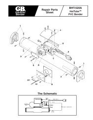
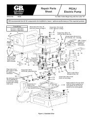
<strong>Gardner</strong><strong>Bender</strong><strong>Repair</strong> PartsSheet<strong>PE20D</strong>, 1/2 HPPORTABLEELECTRIC PUMPRPS-0145 09/00 For Date Codes Beginning with the Letter "C"To Protect Your Warranty, Use Only <strong>Gardner</strong> <strong>Bender</strong> Hydraulic Oil.GB recommends that all kit components be installed to insure optimum performance of the repaired product.Adjustable Relief Valve2,000-10,000 psi(138-690 bar)Pump SwitchREMOTE ON/OFF/MOMENTARY ON2-Way, 2 PositionSolenoid OperatedValveFiller/Vent PortMust be open during operation,closed for shipping only.Remote Control Cord –10 ft. (3 m)5 ft. (1.5 m) Power Cord(no plug on 230V models).DISASSEMBLY NOTE:When removing pump from reservoir, do not destroy the corkgasket that is sealed to the reservoir. Replace the nitrile gasketwith a new gasket from the <strong>Repair</strong> Kit. If the cork gasket isdamaged, a new one is also supplied with the pump repair kit. Itmust be sealed to the reservoir using Loctite #598 Ultra BlackSilicone Sealant..375-18 NPTPort2 Holes, 180° apartfor Ø.375 in. (9,53 mm)cap screw mountingSPECIFICATIONSMaximum PressureMaximum Continuous PressureElectrical Power SourceMotor RatingSound LevelFlow RateMaximum Operating Oil TemperatureReservoir SizeUsable Oil Capacity<strong>PE20D</strong>10,000 psi (700 bar)8,500 psi (590 bar)15 Amp, 115 VAC, 50/60 Hz grounded 1-phase circuit1/2 HP (.37) kW) Universal Motor9 Amps at 10,000 psi (700 bar) and 12,000 RPM, operates to 60-125 VAC85-89 dBA200 in 3 /min (3,4 I/min) from 0 psi to 250 psi (0 to 17,2 bar)20 in 3 /min (0,34 I/min) from 250 psi to 8,500 psi (17,2 to 590 bar)18 in 3 /min (0,31 I/min) from 8,500 psi to 10,000 psi (590 to 700 bar)150°F (65 °C).75 gallon (2,84 liter).50 gallon (1,89 liter)ContentsFigure 1 - Complete Pump ..................................................................2Figure 2 - Top View ..............................................................................3Figure 3 - Side View ............................................................................4Figure 4 - Pump Assembly (exploded view) ........................................5Figure 5 - Top View, Shroud removed..................................................7Figure 6 - Poppet Valve .......................................................................8Figure 7 - Remote Pendant Assembly .................................................9Figure 8 - Solenoid Valve Wire Assembly ............................................9Figure 9 - Electrical Schematic..........................................................10Figure 10 - Wiring Diagram................................................................11
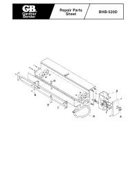
1311291309411248129128126125C123122101Torque Item 123to 15-16 ft-lbs(20,3-27,6 Nm)lubricated.B1CBSECTION "C-C"with valve removed1401D14967Torque Item 149 to 8-10 ft-lbs(10,8-13,5 Nm).38CFigure 2 - Top View<strong>Repair</strong> Parts List for Figure 2Item Part Number Qty. Description Item Part Number Qty. Description9 DA3709900 1 115V Power Cord12 CR759291 3 Cord Bushing38 E300006 1 115V/24V Transformer41 CR881900SR 1 Remote PendantAssembly48 DA12343900SR 1 Wire Assembly, to valve67 A1009245 2 Plug101 DA12490840SR 1 Pump Manifold122 ★C846037 1 Gasket123 ★DA5771290 1 Seat` 125 DC990900 1 Ball Guide126 ★A109164 1 Spring128 DA252028 1 Adjusting Screw129 ★S1167 2 Gasket130 CW306055 1 Lock Nut131 CW307055 1 Cap Nut140 R51245-2 1 Plug149 B1020028 4 Cap ScrewNote: Item 101 (DA12490840SR), includes Item 121 (DA5999900SR) shown on page 6.★Items included in and available only as part of <strong>Repair</strong> Kit PUD1100BK.3
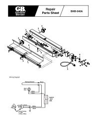
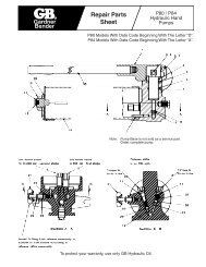
2016154155Torque Item 154 to 27-31 in-lbs(3,1-3,5 Nm).TTorque Item 1812-18 in-lbs(1,4-2,0 Nm)lubricated with1 drop Loctite#242 wet.NOTE: Applysealant to motorend cap at3 locations:around the tierods and thecenter boss.181734.011-.021[0,29-0,53]recess bearingPARTIAL SECTION "B-B"(See Figure 4 for exploded view.)Install bearing(Item 117) flush to .010recessed from surface.Figure 3 - Side View<strong>Repair</strong> Parts List for Figure 3Item Part Number Qty. Description16 DA3763900SR 1 PUD1100/1101B Shroud17 CW261225 6 Eyelet18 F866028 6 Machine Screw20 E1500002 1 Switch34 CW267885 Loctite #598 Ultra Black Sealant154 CU876028 3 Screw155 DA3585186 3 Spacer4
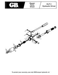
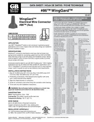
Torque Item 15 to 27-31 in-lbs(3,1-3,5 Nm).Torque Item 109to 10-12 ft-lbs.(13,5-16,3 Nm)lubricated.Torque Item 121 to11-13 ft-lbs.(15,0-17,6 Nm) lubricated.Torque Item 15 to 25-28 in-lbs.(13,5-16,3 Nm) lubricated.Torque Item 109 to 10-12 ft-lbs.(13,5-16,3 Nm) lubricated.Set relief valve to 250-400 psi(17,3-27,9 bar). Stake threadsafter setting pressure.Align tube to face meshto allow for splashlubrication of upperneedle bearing.Install Item 117 flush to.010" (.25 mm) recessedfrom manifold surface.Apply sealant to the topof the reservoir beforeapplying the cork gasket.Use no sealant on thenitrile gasket.Figure 4 - Pumping Assembly5
<strong>Repair</strong> Parts List for Figure 4Item Part Number Qty. Description1 ★DA12088167 1 Gasket (includes 156)3 DA1910900SR 1 .75 Gallon Reservoir10 DA3776006 2 Pin14 DA15066 4 Lock Washer15 B1018121 4 Hex Nut19 CW259298 1 Baffle27 DA608024 1 Vent Plug28 ★B1906503 1 O-ring34 CW267885 Loctite #598 Ultra Black Sealant102 CW179259 1 115V Electric Motor105 CW298950SR 1 .53 Piston Block Assembly106 ★B1007503 1 O-ring107 CW299950SR 1 .24 Piston Block Assembly108 ★B1012803 1 O-ring109 B1008028 4 Screw110 CW252107 1 Bearing114 CW301228 1 Driven Gear115 ★1097057 1 Spring Pin116 ★CW199107 1 Bearing117 CW251107 1 Bearing118 CW302107 1 Bearing119 CW303104 1 Shaft121 DA5999900SR 1 Relief Valve142 DA1011096 1 Elbow143 DA261268 1 Tube144 ★CW467044 1 Retaining Ring145 ★DA445107 2 Bearing146 ★B1007016 1 Ball147 ★DA1564110 1 Spring148 DC433950 1 Plug Assembly150 DA610900SR 1 Relief Valve Assembly154 CU876028 3 Screw155 DA3585186 3 Spacer156 DA12089167 1 Gasket★ Items included in and available only as part of <strong>Repair</strong> Kit PUD1100BK.Replacement Brushes for Electric MotorsPart Number Quantity DescriptionDA9655380 1 Set Brush Set for 115V ModelsDA9657020 1 Set Brush Cap6
2412342161B90˚1A7, 8, 34AREA WITHNO SLOTSTorque Item 8 to 9-12 in-lbs(1,3-1,5 Nm).4, 5Torque Item 5 to 47-53 in-lbs(5,3-6,0 Nm).Figure 5 - Top View, Shroud Removed<strong>Repair</strong> Parts List for Figure 5Item Part Number Qty. Description4 DA6954167 8 Gasket5 B2521028 8 Button Head Cap Screw6 E1100004 1 Thermostat7 C701222 2 Washer8 F658028 2 Pan Head Machine Screw21 DA3712900SR 2 Wire Assembly24 DA11540380 1 Plug34 CW267885 Loctite #598 Ultra Black Sealant7
Torque Item 3 to32-35 ft-lbs(43-47 Nm).31D 1A 1C 1F 1G 1H 1E4Apply Loctite 222Apply Loctite 222 toto threads of item 9threads of Item 99Torque to 15-20 ft-lbs. (20-27 Nm)2 13 6Figure 6 - Poppet Valve<strong>Repair</strong> Parts List for Figure 6Item Part Number Qty. Description1 DA5792949SR 1 Valve Stack (includes items 1A-1H)1A ★ 2 Bushing1C ★ 4 O-ring1D ★ 1 Comp. Spring1E ★ 2 Glyd. Spring1F ★ 1 Seat Spacer1G ★ 1 Poppet Set1H ★ 2 O-ring2 DA4393190 1 Valve Body3 DA5421009 1 Valve Plug4 DA4390118 1 Valve Block6 DA4405900 1 115 V Solenoid Assembly9 PA1417027 1 Set Screw13 B1011803 3 O-ring8
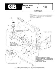
110/220 VACP1L21MHChokeTHERMOSTATJ1-4 J1-3S1220 VACWiring ModificationsM1J1-1 J1-2Motor ACS2T(MOM)(OFF)(MAN)K1T124 VAC110 OR 220 VACRelay-SPSTFigure 9 - Electrical SchematicOptional Dump ValveL1SolenoidS3External Control Station10