NMEA 0183 Multiplexer Brookhouse
NMEA 0183 Multiplexer Brookhouse
NMEA 0183 Multiplexer Brookhouse

Create successful ePaper yourself
Turn your PDF publications into a flip-book with our unique Google optimized e-Paper software.
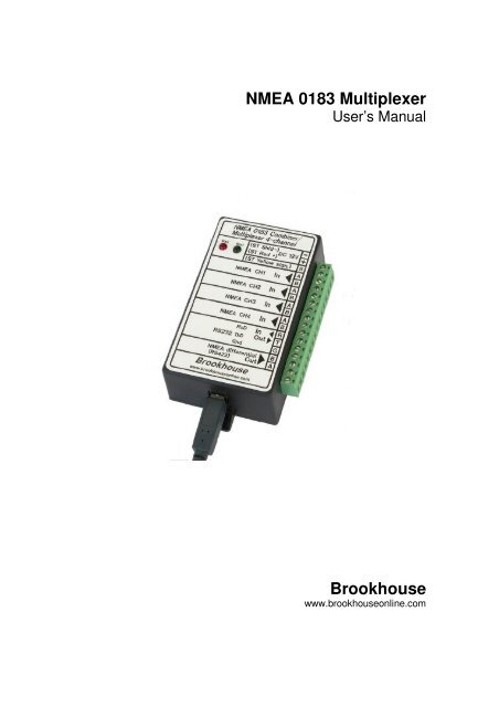
<strong>NMEA</strong> <strong>0183</strong> <strong>Multiplexer</strong>User’s Manual<strong>Brookhouse</strong>www.brookhouseonline.com
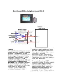
2PrefaceThank you for purchasing a <strong>Brookhouse</strong> <strong>NMEA</strong> <strong>0183</strong> <strong>Multiplexer</strong>. This manualdescribes the installation, configuration and operation of the standard model.Throughout the manual, the multiplexer is ofter referred to as “mux”. Althoughthere are many applications where the multiplexer can be used without acomputer, in the majority of installations a computer is part of the integratedsystem. In the installation description the presence of a (laptop) computer isassumed.InstallationPlease follow the installation instructions for error-free, reliable operation formany years.1. Choose a location where you will install your <strong>NMEA</strong> <strong>Multiplexer</strong>. The<strong>NMEA</strong> multiplexer (with or without repeater display) is usually placed inthe vicinity of the boat’s nav-station, close to the computer. Pleasenote that both the multiplexer itself and the display are not waterproof,they should not be installed in the boat’s cockpit but inside the cabin ata dry, protected location. Avoid connecting sensitive electronics to thesame battery(-bank) as electric winches, start-motors etc.2
32. Determine where your mux will receive its 12V power from. The powershould be switched and fused. The <strong>NMEA</strong> Mux could share the 12Vcircuit for other instruments or the computer. In case you havepurchased the Seatalk option and you will be hooking your mux up toSeatalk, you don’t need a separate power connection. Connect the 3Seatalk wires as described below.3. Make sure there is no power on the multiplexer and the instruments tobe connected.4. Connect the wires for <strong>NMEA</strong> 1, <strong>NMEA</strong> 2, <strong>NMEA</strong> 3 and <strong>NMEA</strong> 4 to thescrew terminals. The connections are clearly indicated. It does notmatter which instrument is connected to which <strong>NMEA</strong> input. They areall equal, unless you use data pacing or automatic (GPS) backupswitching. If you have a mux with Seatalk support and the Seatalk busis connected, the <strong>NMEA</strong> CH1 terminal should be left empty. Consultthe instrument documentation of the manufacturer to determine thepolarity of the <strong>NMEA</strong> output wires. The <strong>Brookhouse</strong> mux inputs areopto-isolated and accept single ended and differential signals. It isoften unknown which kind of signal is output by the instrument to beconnected. If the <strong>NMEA</strong> Out connection on the instrument is markedwith A and B, it is likely to be differential. Connect to A to A and B to B.If the instrument output is marked <strong>NMEA</strong> + and <strong>NMEA</strong> -, connect + toA and – to B. If the instrument has a single wire or connector pinlabelled “<strong>NMEA</strong> out” or “data out”, the signal is single-ended and thecommon ground is used for signal return. In this case connect thesignal out wire to the A terminal of the mux input port and run aseparate ground wire from the instrument to the mux B-terminal. Donot simply connect the ground terminal on the mux to the B-terminal.If a computer serial output is connected to a mux input, connect pin 3to A and pin 5 to B, assuming a 9-pin COM port connector. If polarity isaccidently reversed (A to B and B to A), no signal is received, but noharm is done.5. In installations without Seatalk, make the 12V DC power connection.The red wire is +, the black wire -.6. For Seatalk: The Seatalk bus has 3 wires: Signal, Ground and 12V.Connect the 12V wire (red) to the 12V terminal. Connect the Seatalksignal wire (yellow) to the special terminal and Seatalk shield (blankwire) to -. If port 1 is used for <strong>NMEA</strong>, the Seatalk signal terminal shouldbe empty. Please note that if Seatalk is connected, you also have toconfigure the mux for Seatalk. (see below).7. Prepare the RS232 cable for the (laptop) computer connection. If themux has the integral USB adapter, please read the chapter about USBfurther in this manual.8. Plug the 9-pin D-type connector of the RS232 cable into the COM-portof the computer. If you use USB, follow the instructions for USB.3
49. Connect any <strong>NMEA</strong> listeners you have, such as repeater instrument orradar to the differential output of the mux. Usually a maximum of 3listeners can be connected to the single talker port.10. Double check all connections.11. The <strong>NMEA</strong> multiplexer/repeater is now ready for operation. Applypower to switch it on. Do not switch it on immediately after switchingoff. Always wait for a few seconds.12. It is recommended that you first run the setup procedure to select therequired features. If e.g. you wish to use the Seatalk option, make sureit is enabled.Connection of an autopilotAutopilot control by a GPS.In most integrated computer/instrument systems autopilot-control is a function ofthe navigation software. Chart plotters also provide this function. If autopilotcontrol is not supported by the nav software or if this function should also beavailable when the computer is switched off, in many cases a GPS can also beused directly to send <strong>NMEA</strong> messages to steer the boat to a waypoint or along aroute, depending on the features supported by the GPS. Connect GPS <strong>NMEA</strong>out to one of the multiplexer input ports and connect the multiplexer RS422<strong>NMEA</strong> output to the autopilot input. The autopilot will receive the combinedoutput of GPS and all other instruments and can also be used in wind-vane modeif this mode is supported and if wind-instruments are connected. Note that themux output baud rate has to be set to a value that is supported by the autopilot.This is usually 4800 bps.Autopilot control by navigation softwareIf the navigation software supports autopilot control (auto pilot track mode), thefollowing applies.Provided that the mux is connected to the computer as shown in the diagram onpage 2, auto pilot sentences (APA, APB etc.) are received in the mux via theRS232 RxD terminal. If the mux has the integral USB option, there is a (blue)wire brought out the mux enclosure under the large green connector. It carriesthe data sent by the computer via USB. This wire has to be connected to the RxDterminal to receive computer data via USB.Data received by the mux on the RS232 RxD port is combined with the datareceived via the standard input ports CH1 – CH4. The RS232 RxD port iseffectively a fifth input, so the standard <strong>NMEA</strong> multiplexer actually combines 5input data streams.The 5 th input can also be used for other purposes, such as connection of an AISreceiver. Refer to the chapter on AIS elsewhere in this manual.4
5In the above described set-up, the auto pilot control sentences, such as APA,APB, XTE, are included in the combined multiplexer data output stream. Theauto pilot is connected to the multiplexer RS422 output and receives allcombined sentences, but it only uses the ones that are required for steering.Some auto pilots have the ability to display other <strong>NMEA</strong> data, as a repeaterfunction. The same combined data stream is output via RS232 and USB (ifinstalled). This means that the computer also receives back the auto pilotsentences it has generated, but these are ignored.An advantage of this wiring method is that the auto pilot can receive the <strong>NMEA</strong>steering sentences from either the GPS directly or from the navigation softwareon the computer, without the need of physical switching between the two.Alternative auto pilot connection methodThere is an alternative method of connecting the auto pilot. If the multiplexer’sRS232 RxD port has to be used for a different purpose, the auto pilot can bewired directly to the computer output via the same mux-computer cable, butbypassing the multiplexer. The auto pilot (input) feed cable has to linked to thecomputer-mux cable as follows:If the computer connection is via RS232, the computer TxD wire has to beremoved from the mux RxD terminal and connected to the auto pilot input cable(<strong>NMEA</strong> in +). In case of USB, the (blue) USB wire has to be disconnected fromRxD and connected to the AP feed cable (<strong>NMEA</strong> In +). In both cases the wire for<strong>NMEA</strong> – of the auto pilot has to be inserted in the mux RS232 Gnd terminal.Although the multiplexer is bypassed in this way, only the single computer port isused for in- and output and the mux USB interface is used to convert thecomputer USB output to RS232 for input by the AP.The <strong>NMEA</strong> standard recommends a differential signal (RS422, “<strong>NMEA</strong> out”) forthe connection to the auto pilot. Whilst RS422 is the preferred signal, as used inthe standard mux wiring method described on page 4, the RS232 signal isacceptable for auto pilot input in most cases.Note:If the Autopilot only accepts a baudrate of 4800 BPS , this will dictate thebaudrate-setting of the multiplexer output and computer port. Thecomputer port baudrate setting applies to both directions, transmit andreceive. If you need to have a mux output data rate of higher than 4800due to high <strong>NMEA</strong> traffic intensity and if the autopilot accepts 4800 bpsonly, there are several options to satisfy these conflicting requirements.Also refer to “baud rate selection” on page 9.5
6Uploading waypoints from the computer to a GPS via the multiplexerIn many integrated systems, waypoints are only kept in the computer and theGPS ‘s only function is to provide lat/lon of the current position. Navigation tasksare all performed by the computer. However, a number of skippers/navigatorsprefer to copy waypoints to the GPS, so that the GPS can take over thenavigation task if necessary, as a backup. Waypoints generated and managed insoftware running on the computer can be uploaded to the GPS. If standard<strong>NMEA</strong> sentences are used for waypoint definition, the GPS <strong>NMEA</strong> input port canbe connected to the mux RS422 ouput port in parallel with the auto pilot (ifpresent) and other <strong>NMEA</strong> listeners.If a special interactive protocol is used for communication between the computerand the GPS, it is recommended not to wire the computer-GPS link via themultiplexer. <strong>NMEA</strong> messages generated by other instruments are combined withGPS data and can disturb the proper interaction between GPS and computer.In this case, it is recommended to install a DPDT switch (double pole, doublethrow) that switches the GPS <strong>NMEA</strong> in and out ports between multiplexer andcomputer directly.6
7LCD repeater display installationThe <strong>NMEA</strong> <strong>Multiplexer</strong> model with LCD also works without the LCD connected.Do not plug the LCD in the multiplexer while the power the multiplexer power ison. If required, drill a hole for the cable. If you want to keep the hole as small aspossible, remove the shell of the plug and carefully bend the wires sideways. Ahole of 18mm will now be sufficient to feed the cable and plug through. Bend thewires back afterwards, make sure you have not broken any and replace the shell.Note: Although the plug used for the LCD-<strong>Multiplexer</strong> connection is thesame as used for VGA monitors, never plug a VGA monitor into themultiplexer and never plug the LCD into a VGA connector of a PC. Thepin-outs are not compatible and you will damage the LCD or multiplexer.7
8ConfigurationThe setup menuThe setup menu is used for setting options and uploading of filtering/editing andLCD directives. The multiplexer has to be connected to the computer via theRS232 port or USB. No special software is required. Use standard Windowsprogram Hyperterminal or any other terminal program. Configure the terminalprogram (Hyperterminal is assumed in this description) for direct communicationvia COMx (the port the mux is connected to). Select the following settings:• Baudrate 4800 for standard model multiplexer or current mux baudrate ifchanged previously.• 8 bits, no parity• No flow control• To list filter/editing or LCD directives one per line, during uploading:In the file menu, select properties. Under settings select Ansi terminal,under ASCII setup, tick Send line ends with line feeds.To enter setup mode, press the keyboard ESC key or / (slash) key inHyperterminal ( Hyperterminal has to be the active foreground application),while you switch the mux on. The mux recognises the ESC or / key only duringthe three start-up flashes of the green status led. The following menu shouldappear:*** Select option by entering single digit or letter: ***1 - Set baudrate to 4800.2 - Set baudrate to 9600.3 - Set baudrate to 19200.4 - Set baudrate to 38400.5 - Enable 5th input port.6 - Disable 5th input port.I - Set port 1: Seatalk, <strong>NMEA</strong> ID,= $II.S - Set port 1: Seatalk, <strong>NMEA</strong> ID,= $ST.N - Set port 1: <strong>NMEA</strong>, Seatalk disabled.F - Upload filtering/editing definitions.L - Upload LCD screen definitions.A - GPS backup: priority port 1, backup port 2.B - GPS backup: priority port 2, backup port 3.C - GPS backup: priority port 3, backup port 4.D - Disable GPS backup feature.P - <strong>NMEA</strong> Data Pacing (port 2, 1 sec.).Q - <strong>NMEA</strong> Data Pacing (port 3, 2 sec.).R - Disable <strong>NMEA</strong> Data Pacing.X - Exit setup.***Select the option(s) you require by pressing a single letter or number and followthe instructions from the mux. Use uppercase for letters.8
9Note 1:Detailed instructions with screen-shots for Hyperterminal can also be found onthe following page on the <strong>Brookhouse</strong> website:www.brookhouseonline.com/Hyperterminal.htmBaud-rate selectionThe baud rate of the multiplexer’s RS232, USB and RS422 ports can be set to4800, 9600, 19200 or 38400bps.If no auto pilot has to be connected, set the baudrate to one of the higher valuesto ensure sufficient bandwidth.The internal buffers of the multiplexer allow for larger amounts of data to bereceived than can be transmitted at the same time via the output port. However,it will be clear that this is only for short periods. It is not possible to have asustained total data-inflow that is larger than the capacity of the output port, evenwith very large buffer lengths. As all <strong>NMEA</strong> instruments send data (<strong>NMEA</strong>sentences) in bursts every 1 or 2 seconds, the time gaps reduce the averageinput rate and the risk that an overflow situation will occur is small, even with theoutput port set to 4800.If an auto pilot is part of the system, the baudrate usually has to be 4800.Depending on the amount of data produced by the connected instruments, 4800bps may provide insufficient bandwidth for the combined data. This may result is(occasional) buffer-overflow. If such a situation arises, there are 3 options toresolve this:1. Use filtering to remove redundant data to reduce <strong>NMEA</strong> traffic density.In most cases there are many unused <strong>NMEA</strong> sentences that can befiltered out.2. Activate ‘Data Pacing’ in the setup menu to increase the time-gapbetween <strong>NMEA</strong> sentences3. Set the baud rate to a higher value and connect the auto pilot to thecomputer independently.In the configuration setup of your computer’s navigation/chart plotting software,set the baudrate of the COM port to the same value as the mux.The baud-rate of the standard model multiplexer’s <strong>NMEA</strong> input ports is fixed4800 baud. Set the baud-rate of the <strong>NMEA</strong> outputs of the instruments to matchthis. 4800 is the standard <strong>NMEA</strong> transmission rate and most instruments will usethis as the default setting. The transmission speed of modern GPS’s is usuallyselectable.9
10For <strong>NMEA</strong> <strong>Multiplexer</strong> units with LCD display:The Setup menu is available for all models, including the mux with LCD, but forthe model with LCD an additional method for selecting some of the options isavailable using the LCD and selection pushbutton.1. Turn the power off and wait for a few seconds.2. Depress the selection push button and keep it depressed while power isapplied.3. The words “Select Option” are displayed on the LCD. Release the pushbutton.4. Press/release the selection push button until the required baud-rate isdisplayed. Only 4800 and 9600 bps can be selected this way. Use thesetup menu if baudrate 19200 or 38400 is required.5. Press the selection button and wait until the word “Set” appears.6. Turn the unit off and wait for a few seconds before switching it on again.7. Next time the <strong>NMEA</strong> mux is switched on, the selected baudrate will beeffective.Setting <strong>NMEA</strong> or Seatalk support for port 1All <strong>Brookhouse</strong> <strong>Multiplexer</strong> modelsIf you have purchased the Seatalk option, port 1 has been preset to Seatalkmode and you don’t need to do anything, unless you want to change the SeatalkID (see below).The <strong>NMEA</strong> Seatalk ID is the 2 letter code, preceeded by $ (dollar sign), that themux uses as the prefix for all <strong>NMEA</strong> messages that are the result of the Seatalkto <strong>NMEA</strong> conversion. The factory setting for the <strong>NMEA</strong> Seatalk ID is $II(Integrated Instruments). Sometimes it is advantageous to distinguish the muxgeneratedsentences from other sentences starting with $II. For this reason $STis offered as a menu-selectable alternative to $II. Most software and instrumentsjust look for the $ and ignore the ID code, but if $ST is not accepted, use theSetup menu to change it to II. Alternatively, load an editing directive (Substitute)to change the ID ‘on the fly’ to any required code.Also use the setup menu to disable the Seatalk conversion if required. WithSeatalk conversion disabled, port 1 accepts standard <strong>NMEA</strong> data.For <strong>NMEA</strong> <strong>Multiplexer</strong>s with LCD:For multiplexers with the optional LCD, an alternative way of enabing/disablingthe Seatalk option and selecting the Seatalk <strong>NMEA</strong> ID is offered:10
111. Turn the power off.2. Depress the selection push button and keep it depressed while power isapplied.3. The words “Select Option” are displayed on the LCD. Release the pushbutton.4. Press/release the selection push button until “Port 1 <strong>NMEA</strong>” appears ifyou require <strong>NMEA</strong> for port 1 or until “Port 1 Seatalk” appears if Seatalksupport is required.5. Press the selection button and wait until the word “Set” appears.6. Turn the unit off and wait for a few seconds before switching it on again.7. Next time the <strong>NMEA</strong> mux is switched on, the selected protocol for port 1will be effective.Follow the same procedure for selecting the <strong>NMEA</strong> sentence ID (II or ST) forSeatalk data.Note: You can select baudrate, Port 1 protocol and Seatalk <strong>NMEA</strong> sentence IDwithout switching the unit on and off each time.USBThe integral USB adapter allows connection of the <strong>Multiplexer</strong> to a computerUSB port. USB V1.1 is supported. A <strong>Brookhouse</strong> supplied driver has to beinstalled in the computer. This creates a virtual COM-port for communication ofnavigation software with the multiplexer. The integral USB interface convertsUSB to RS232 and vice versa. This has the advantage that data sent from thecomputer via USB is also available at the multiplexer-end as a RS232 signal.If the computer has a serial RS232 port plus a USB connection, the mux outputcan be connected via both paths. This makes it possible to run 2 applications inthe (laptop) computer that both use the output of the <strong>NMEA</strong> multiplexer.Driver InstallationConnect the <strong>NMEA</strong> mux to the computer USB port with the supplied cable. Leavethe power of the mux off at this stage. Windows will usually recognize the USBdevice as soon as it is connected or as soon as the computer is switched on withthe cable already plugged in. Follow the Windows instructions for installing newdrivers. If the mux has not been connected before, Windows (all versions) will11
12ask for the driver diskette or CD supplied with the USB device. If the USB device(<strong>NMEA</strong> Mux) is not automatically detected, go to “My Computer”-“Add newhardware”.Although there are differences between Windows versions in the way new driversare installed, the principle is the same: Specify the location where the newdriver can be found. When asked which location should be included in thesearch, click on Browse and find the drive and directory where the driver isstored.After the installation of the driver is complete, go to “My Computer”-“ControlPanel”-“System”-“Device Manager”. Click on “Ports” and check which portnumber has been assigned to the virtual USB COM port. Use this COM portnumber in the configuration section of your Navigation software or otherapplication that will read the <strong>NMEA</strong> mux output.Make sure that the baud rate of the <strong>NMEA</strong> Mux and the baud rate in the COMport configuration of the navigation software are the same. Other requiredsettings are: 8 bits, no parity, no flow control.If for some reason the USB connection does not seem to be working or theapplication reports errors when attempting to open the port, terminate theapplication, switch off the multiplexer, remove the USB cable from themultiplexer, wait a few seconds and plug the USB cable back into the mux. Thenrestart the software, and switch on the <strong>NMEA</strong> mux.“Crazy Mouse” ProblemUnder certain circumstances, if the USB device is connected and alreadysending data to the computer when Windows is started up, Windows will “think”that the connected device is a pointing device (Microsoft Ballpoint device orother). This is a general problem with USB serial devices and can also occurwhen a GPS or multiplexer is connected via USB.Here follows a remedy:Switch the multiplexer off to stop sending data to the computer but leave the USBconnection intact. This will stop the uncontrolled cursor moving over the screen.Go to My Computer > Control Panel > System. Click on Hardware tab, DeviceManager and click on Mice and other pointing devices. Find the device that wasincorrectly identified as a mouse (Ballpoint device) and double click on it for theproperties. Under Device Usage select Disable.From now on the USB device will no longer be recognized as a mouse.12
13<strong>NMEA</strong> Control functionsGPS backup switchingMany navigators decide to install a second GPS for backup, to take over from theprimary GPS when it fails, for whatever reason. However, it is not alwaysimmediately known if the primary GPS stops sending data to the navigationsoftware. If the navigation computer has been unattended for some time, theposition in the electronic chart may not have been updated for a while becauseno GPS <strong>NMEA</strong> sentences were received.Typically, the boat's position is checked if there is a potential navigational hazard,when an up-to date position is most needed. To discover at that time that theGPS has stopped could not be more inconvenient and dangerous. Preparing abackup GPS to replace the primary can take valuable minutes. The solution liesin using a <strong>NMEA</strong> multiplexer and have the primary and a backup GPSpermanently connected. If one GPS stops, the other will still send GPSsentences with lat/lon. Chances that both GPS units fail at the same time arelow.However, permanent connection of 2 GPS units can be undesirable, because thefrequency at which lat/lon is sent to the navigation software is doubled andsentences may be sent through the multiplexer with a very short time-interval, asthe 2 GPS's are independent. The navigation software may not be able to handlethe data from 2 GPS's and/or may slow down or even fail.All <strong>Brookhouse</strong> multiplexers now have a feature that resolves this problem in anelegant way. One multiplexer port can be designated the "primary GPS port" anda second port the "GPS back-up port" in the setup menu. As long as <strong>NMEA</strong>sentences are being received via the primary GPS port, data from the back-upport is blocked. If no data is received for 10 seconds, the back-up port isunblocked and the backup GPS takes over from the primary. When the primaryGPS starts sending <strong>NMEA</strong> data again, data from the back-up port is no longersent to the computer.If GPS backup switching is used with channel 1 as the primary input channel,port activity (or the lack thereof) is not used to determine if the GPS is active ornot. Instead, the data stream is analyzed for the presence/absence of a certain<strong>NMEA</strong> sentence. This way, if the data stream received via channel 1 alsocontains other than GPS data, GPS (non)activity can be sensed, while otherinstruments continue sending data. This feature has been designed to senseGPS activity in systems with Seatalk. If the Seatalk option is active, the Seatalk-<strong>NMEA</strong> conversion in the mux results in a mixture of <strong>NMEA</strong> sentences, includingGPS sentences, so if the GPS stops sending, this cannot be detected by lookingat port activity only. To enable selective sensing of the sentence type on channel1, two steps are required:13
141. Select GPS backing switching option A in the mux setup menu. (primaryport is 1, backup is 2)2. Upload the following script with option F:*C,1,IIRMC,0,2,0,0*E<strong>NMEA</strong> Data PacingThe <strong>NMEA</strong> standard recommends that <strong>NMEA</strong> sentences produced by individualinstruments are sent at a frequency not higher than once per second. Someinstruments, especially some electronic compasses and engine function sensors,send their <strong>NMEA</strong> sentences at much higher frequencies. This can cause seriouscongestion in integrated instrument/computer systems, especially if thesesentences are combined with data from other <strong>NMEA</strong> talker sources. The amountof data to be processed by the computer software can be so large that it slowsdown significantly and some programs stall.Many of the values contained in sentences sent at these high frequencieschange very little from one sentence to the next. For example, it is unlikely thatthe vessel's heading changes much in half a second time. The same headingvalue is likely to be sent repeatedly over and over again.The Data Pacing mechanism in <strong>Brookhouse</strong> <strong>NMEA</strong> <strong>Multiplexer</strong>s, if activated,blocks data received from a selected port for short periods, to insert time gaps inthe data stream and give the computer or other <strong>NMEA</strong> listener some "breathingspace". For example, one second interruptions can make a considerabledifference and alleviate the system load whilst it is unlikely that the sentencessuppressed during that single second will contain significant changes. After ablock period, sentences are allowed through again for a short period of time.The block period always starts after a complete sentence has been received andwhen after the time-out data is sent through again, it will always start with thebeginning of a new sentence ($).Together with the filtering feature, data-pacing allows the user to fine-tune andoptimize the integrated instruments/computer system to the maximum.Data-pacing is activated from the mux set-up menu, but if only the standard muxfunctionality is required, nothing has to be done, as with other advancedmultiplexer features.14
16standard <strong>NMEA</strong> ports and transmitted as a single data stream to computer orchartplotter at 38400 bps.The high baudrate, which also applies to the mux output port, means thatstandard <strong>NMEA</strong> listeners at 4800bps, such as auto pilots, cannot be connectedto the mux output port.There are many applications where this is not a problem. For example, insystems where the auto pilot is connected to a chart plotter via Seatalk, andcomputer AP control is not required, the lack of <strong>NMEA</strong> output at 4800bps is not adisadvantage.For those configurations where both 38400 in and output for AIS plus 4800 bps<strong>NMEA</strong> output is required, <strong>Brookhouse</strong> has 2 different models of <strong>NMEA</strong>multiplexers with baudrate conversion: models AIS and AISC.The four standard multiplexer input ports are opto-isolated. The RS232 portused for connection of an AIS receiver (standard mux) is not opto-isolated. Thepopular AIS receivers have been designed for direct connection to a (non optoisolated)RS232 computer port and connection via the mux RS232 port presentsno problems for any of the popular AIS receivers available.Use of the RxD portThe 5 th input port (RxD terminal on the multiplexer) is also used for bi-directionalcommunication with a computer during configuration/setup of the multiplexer.Multiple devices cannot be connected to an input port at the same time.Therefore, the AIS receiver (or other <strong>NMEA</strong> talker, HS or standard) should onlybe connected after the setup procedure has been completed and the port is freefor other use. After setup, the computer Tx D wire has to be disconnected fromthe mux RxD screw terminal and the AIS receiver or other <strong>NMEA</strong> talker can nowbe connected. If setup is regularly required for uploading filter/editing data orLCD screen definitions, installation of an external single-pole change-overswitch may be considered for convenience.If the communication with the computer is via USB, the integral USB-RS232converter has to be disconnected from the RxD terminal for the same reason asexplained above, before the AIS receiver can be connected.For this purpose, the blue wire in the RxD terminal for models with USB optionshould be removed and insulated after configuration, before the AIS receiver orother <strong>NMEA</strong> talker is connected.If no AIS receiver or other external <strong>NMEA</strong> talker is installed, the RxD port canstay connected to the computer all the time. After mux configuration, <strong>NMEA</strong> datasent back to the mux by the computer, will be combined with the other inputs toa single data stream. For example, auto-pilot control sentences generated by thecomputer nav software can be input by the mux in this way to be combined with16
17other input data. In case of USB communication the blue wire can stay in place.Also refer to the chapter in this manual dealing with autopilot connections.Baud rate considerationsIf a high-speed <strong>NMEA</strong> talker is connected, a consequence is that the outputbaudrate of the multiplexer has to be set to the same rate. The risk of data-losswould be too high if the output baudrate would be lower. Therefore the baudrateof the 5 th input port and the mux output data rate are coupled and automaticallyset to the same value during the mux setup procedure. As standard <strong>NMEA</strong>listeners such as auto pilots and repeater instruments usually accept only4800bps, these cannot be directly connected to the mux output if the selectedbaudrate is higher than 4800. However, in most navigation software packages aseparate output port can be configured at 4800bps for auto-pilot control. Thereare also <strong>Brookhouse</strong> multiplexer models available with baudrate conversion toallow connection of low-speed <strong>NMEA</strong> listeners.<strong>Multiplexer</strong> operationThe multiplexer is fully automatic. Once power is applied, it starts looking forinput data on all 4 input ports and outputs <strong>NMEA</strong> sentences on the RS232 outputport.LED’s (Light Emitting Diodes)The two led’s have the following function:Red led (pwr):Green led (stat):This is on when power is supplied to the multiplexer.When the multiplexer is switched on, three short flashesindicate that the processor is running and no faults havebeen detected. After initialisation the green led is on when a<strong>NMEA</strong> sentence from one of the input ports is beingtransferred to the output port.LCD (only for <strong>Multiplexer</strong> model with LCD)The LCD is used for displaying selected <strong>NMEA</strong> data found in the data-stream ofany of the four connected instruments. The multiplexer is supplied with a numberof screen definitions for often displayed data. The user can change thesedefinitions and/or add more to display additional data or data-combinations. The17
19<strong>NMEA</strong> sentence monitoringIf you wish to check if all <strong>NMEA</strong> data sentences that you are expecting areincluded in the output of your instruments and the <strong>NMEA</strong> multiplexer, you caneasily verify this by running Windows program Hyperterminal (underAccessories). This will display all “raw” <strong>NMEA</strong> data, sentence by sentence. Don’tforget to set the correct baud rate. Also, after changing the baud rate,Hyperterminal has to be terminated and re-started. You can also use yourcomputer to simulate <strong>NMEA</strong> instruments on the input ports of the <strong>NMEA</strong>multiplexer/repeater. Do not use Hyperterminal for this purpose, because themultiplexer will “lock” on the input port until a LF (Line Feed) character isencountered. There is an <strong>NMEA</strong> Instrument simulation program available (freetrial version) on www.sailsoft.nlSupportThe software for our products is regularly updated and new functions added. If infuture you require a new features which are not included in the version of theproduct you own, we are happy to install the latest software in your unit for asmall service fee.Questions or CommentsPlease feel free to send us an email to support@brookhouseonline.com in caseyou have questions, requests or comments. On the websitehttp://www.brookhouseonline.com you can find more technical info.19
20Specifications• 4 opto-isolated “Listener” (Input) ports for the connection of <strong>NMEA</strong>"talkers" (GPS, Windinstr. etc.).• RS232 input (Computer or AIS) for fifth input.• 1 Output RS232 port (typically for connection to computer)• 1 Output RS422 port (differential <strong>NMEA</strong> talker port)• Data speed: 4 Input ports: 4800 bps (standard <strong>NMEA</strong> baud rate), RS232Input & Output: 4800/9600/19200/38400 bps selectable in setup mode,default 4800 bps.• Indicators: red LED for power, green LED for data-transmission.• Supply Voltage: DC 9-35 Volts.• Reversed polarity protection.• Power Consumption: 45 mAmps. @ 12V (with all ports active)• Physical size: 110x65x37mm (hxwxd)• Weight: 120 grams• Mounting: bulkhead mounting with screws.• <strong>NMEA</strong> management and control:o <strong>NMEA</strong> Sentence Filteringo <strong>NMEA</strong> Sentence editing “on the fly”o Automatic port switching (mainly for GPS backup)o Data pacing for fast talking sensors and electronic compasses.• Options:o Raymarine Seatalk to <strong>NMEA</strong> conversion.o USB for computer connection.o User programmable LCD (compact repeater)DisclaimerAlthough we do our best to make our products highly reliable, we cannot accept any responsibilityfor personal injury, loss of life or material damage as a result of malfunctioning of our products.20