MTVT 84 - TERMAN
MTVT 84 - TERMAN
MTVT 84 - TERMAN
- No tags were found...

Create successful ePaper yourself
Turn your PDF publications into a flip-book with our unique Google optimized e-Paper software.
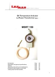
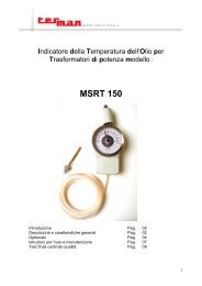
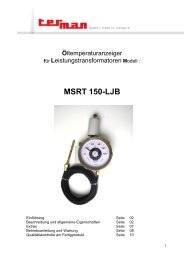
Microswitches equippedThermometer type :<strong>MTVT</strong> <strong>84</strong>Description and general specificationsOperating instructions and maintenanceFinished product quality control testspagepagepage0203041
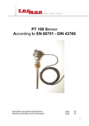
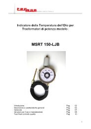
Description and general specifications.This instrument is designed to measure and control the temperature in oil filled distribution transformers andis made for outdoor mounting in as well tropical or arctic climates (ambient temperature range -40°C /+70°C). All components are made of corrosion resistant or surface treated materials.This thermometer is fitted with 1 or 2 change-over (SPDT) microswitches working both normally open andnormally closed (three terminals each microswitch) and is supplied with a junction board with 3 or 6 terminals+ earth. Max. cable section = 2,5mm 2 .Temperature sensing system : expansion type(liquid filled system), compensated for ambienttemperature changing by means of a bimetallicspring.Casing : aluminium alloy with powder paintinghigh protection degree. On request case can beprovided with an air breather device for ventilation.Mechanical protection degree : IP 65.Measuring range : -20 / + 120°C.Switches making and breaking capacity (noninductive) :5A 250V AC250mA 250V DC500mA 125V DC.Insulation test : 2000V 50Hz between terminalsand earth for a 60 seconds time.Measuring tolerance : 1,5% of full scale value.Commutation tolerance : 2% of full scale value.Pos. Description1 Case2 Cover3 Connection4 Bulb5 Data plate6 Cable gland7 Switch setting knobs8 Max temp indicatingpointer9 Breather device2
Operating instructions and maintenance.Mounting : mount the instrument on its machine or plant by putting the thermometer bulb into the thermometerpocket on the transformer cover and by screwing the thermometer connection.Attention : the connection must be locked by using a spanner. Trying to lock the connection by rotating thermometer'shead may damage the instrument.Before locking the thermometer take care that its dial is oriented to consent a perfect readability.Contact setting : remove the thermometer cover by unscrewing the 4 stainless steel screws.Rotate the knob of each contact till the small pointer is located at the desired set point temperatureRe-position the cover taking care that the sealing gasket is correctly located into its seat ant that the maxtemperature pointer (if any) is on the right side of the indicating pointer. Screw the stainless steel screws.Cable layout : the numerations 1-2 indicate the microswitches progression. Close to the terminals you willfind the following abbreviations :• C = common• NO = normally open• NC = normally closedthat allow the operator to choose the desired cable layout.When connecting the microswitches terminals don't forget to connect the earth terminal too.MaintenanceNo particular maintenance is required. Only periodical inspections ( typical interval 12 months ) to verify precision,functions and electrical connections.When the instrument is equipped with polycarbonate lens, cleaning must be done with care in order to avoidscraps on the surface. Use water and soap only.3
Finished product quality control tests.Instrument calibration : carried out through thermostatic baths controlled by a computer system.The procedure varies according to instruments scale.The calibration procedure, being the thermometer scale -20 / +120°C is made using 5 different baths set atthe following temperatures :bath 1 = -20°Cbath 2 = 20°Cbath 3 = 50°Cbath 4 = 100°Cbath 5 = 115°CCalibration procedure :Step 1: a check is carried out to see whether the temperature taken by the instrument under test differs fromthat taken through the sample sensor by more than the 70% of the maximum allowed instrumentreading tolerance value. This test is performed by sequentially plunging the TEMPERATUREINDICATOR bulb into successive temperature increasing thermostatic baths : -20°C / +20°C /+50°C / +100°C / +125°C.Step 2: the instrument is heated until the instrument pointer exceeds by 20% the angular full scale value.Step 3: step 1 is repeated, but inversely.Microswitches actuation test :performed through a computer controlled testing unit .The bulb is immersed in a thermostatic bath. The computer changes the temperature inside of the bath andby means of suitable sensors verifies the commutation tolerance, the commutation differential, the electricalcircuits of each microswitch. At the end of the test a report is directly printed by the computer.Check of instrument mechanical protection degree : IP 65.Insulation test : carried out by means of a microprocessor controlled testing unit.Note : all the collected data are immediately transferred, by means of the computer net, to the quality controland to the design departments to be supervised and evaluated.In our files, we keep all the above mentioned informations and we can supply to the customer detailedreports regarding the performances of each instrument delivered.I EDITION AUGUST 2006Terman '90 S.r.l., Via Ghisalba, 13-20/21, 20021 Bollate (MI) – Italy. Tel: +39 02 38 30 37 12, Fax: +39 02 38 30 37 19,E-Mail info@terman.com, www.terman.comC.F./P. IVA IT 09970270154 – C.C.I.A.A. 1332904 – Trib. Milano Reg. Soc. 302729 – Cap. Soc. € 119.0004