Multiband Microwave Transverters for the Rover - W1GHZ
Multiband Microwave Transverters for the Rover - W1GHZ
Multiband Microwave Transverters for the Rover - W1GHZ
- No tags were found...

You also want an ePaper? Increase the reach of your titles
YUMPU automatically turns print PDFs into web optimized ePapers that Google loves.
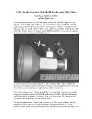
<strong>the</strong> LO section of <strong>the</strong> board. Note that <strong>the</strong> capacitors are at <strong>the</strong> shorter location on <strong>the</strong>quarter-wave chokes – this copy is <strong>for</strong> 3456 MHz.Then move C6 to connect <strong>the</strong>LO to <strong>the</strong> mixer. Solder <strong>the</strong>mixer down carefully, since <strong>the</strong>bottom is open (turn it over andadmire <strong>the</strong> tiny trans<strong>for</strong>mersfirst), making sure to align itaccording to <strong>the</strong> picture, Figure15. The mixer pipe-cap filter istuned using <strong>the</strong> receive port as atest point, jumpering <strong>the</strong> MMIClocation A1 with a wire asshown in Figure 16. Only <strong>the</strong>splitter resistor, R1, is needed atthis point. With only <strong>the</strong> LOrunning, set <strong>the</strong> pipe-cap tuningscrew <strong>the</strong> same height as <strong>the</strong>LO screws, <strong>the</strong>n tune <strong>for</strong> a peak– this is at <strong>the</strong> LO frequency.Then apply 0 dBm at 144 MHzto <strong>the</strong> IF port. Now adjust <strong>the</strong>screw <strong>for</strong> a larger peak at <strong>the</strong>Figure 14 LO section of Transverter board