TECHNICAL MANU AL CD 30÷520 06.06 M T E 0 11 2 5 6 ... - Chiller
TECHNICAL MANU AL CD 30÷520 06.06 M T E 0 11 2 5 6 ... - Chiller
TECHNICAL MANU AL CD 30÷520 06.06 M T E 0 11 2 5 6 ... - Chiller
- No tags were found...

Create successful ePaper yourself
Turn your PDF publications into a flip-book with our unique Google optimized e-Paper software.
R22A I R C O N D I T I O N I N GR407CR410AR134a<strong>TECHNIC<strong>AL</strong></strong> <strong>MANU</strong><strong>AL</strong>MODULAR AIR COOLED LIQUID CHILLERS AND HEATPUMPSWITH AXI<strong>AL</strong> FANS AND SCROLL COMPRESSORS FROM 30 kWTO 520 kW.Serie/Series/Serie/Série Emissione/Edition/AusgabeIssue<strong>CD</strong> 30÷520 <strong>06.06</strong>Catalogo/Catalogue/Katalog/Brochure Sostituisce/SuperseedesErsetzt/RemplaceMTE0<strong>11</strong>2560020 -A21
2<strong>CD</strong> 30 ÷ 520
<strong>CD</strong> 30 ÷ 520CONTENTSModular Air-cooled <strong>Chiller</strong> System1- Modular air-cooled <strong>Chiller</strong> System1. Summarization ..........................................................................52. Nomenclature ............................................................................63. Outlook view..............................................................................74. System principle figure ..............................................................75. Specification ..............................................................................96. Digital scroll compressor ...........................................................127. The capacity control of the new modular chiller.........................158. Advantages of digital scroll compressor ....................................179. Features ....................................................................................1710. Unit installation ..........................................................................23<strong>11</strong>. Water system installation...........................................................2612. Wiring ........................................................................................2713. Debugging .................................................................................2914. Maintenance..............................................................................3315. Troubles and solutions...............................................................3716. Wiring diagram (main unit) ........................................................4017. Wiring diagram (auxiliary unit) ...................................................4<strong>11</strong>8. Wiring & communication diagram..............................................4319. Installation system figure ...........................................................453
<strong>CD</strong> 30 ÷ 5202- Electric control1. Outlook view .............................................................................462. parts descriptions......................................................................473. Failure & protections codes ......................................................523- Wire controller1. Outlook view .............................................................................532. Pattern & buttons description....................................................543. Basic operating conditions........................................................564. Function description..................................................................574
<strong>CD</strong> 30 ÷ 520Air-cooled heat-pump module unit1.SummarizationAir-cooled heat-pump unit is a kind of central air-conditioner unit which adopts air as the cooling(heating) source and water as cooling (heating) medium. As a sort of integrated equipment, it needno cooling tower,cooling water pump,boiler and the corresponding auxiliary parts such as pipesystem etc, which makes the structure simpler, saves installation space, convenient maintenanceand energy saving, thus it is very suitable for areas that are short of water. Air-cooled heat-pumpunit is the first priority in the engineering design for the following conditions:Hot winter and cold summer;No heating boiler and heating-supply pipe system;Heating supply pipe system is unstable or the supplying time is short;Need air-conditioning whole year.The centralize and half-centralize central air-conditioning system that consist of Air-cooledHeat-pump Unit, Fan Coil and Air-condition Box have advantages of flexible arrangement andvarious control methods.Maxa Commercial Digital scroll air-cooled heat-pump module unit is designed and produced onthe basement of sufficiently absorbing the top technology in AC areas, adopting self-controlcomponents with high quality made by world famous producers. Moreover, after optimizing, unit canrun more efficiently and more stably. One 60kW module consists of two 30kW units, and severalmodules can be formed into a digital scroll air-cooled heat-pump module unit by connecting eachmodule’s inlet & outlet pipeline in series. The whole unit consists of 1-8 modules (or 2-16 units) andthe max capacity is 480kW(520kW).Maxa Commercial Digital scroll air-cooled heat-pump module unit can be used widely in civilconstruction of AC engineering and industrial engineering, such as hotel, villa, restaurant, hospital,factory, etc. It is a wise choice for areas where water is insufficient or there are strict limits on noiselevel and surroundings.Relevant noun description:• Unit——one independent outdoor unit, including two entire refrigeration system and oneelectric controller. (One 60kW module consists of two 30kW units)• Main controller ——every electric control system of unit can accomplish the following functionsindependently: Mode input; Data collection; Output interface control; Failure alarm analyzing.5
<strong>CD</strong> 30 ÷ 520• Digital scroll air-cooled heat-pump module unit——a unit consists of one or more(1÷8) than onemodules (2÷16 units).• Wire Controller——the interface between the module and human, it can receive the operationcommand and sent them to main controller, meanwhile receive the running state data anddisplay them.2. NomenclatureC D – M 30Cooling capacity (kw)A: Auxiliary unitM: Main unitDigital<strong>Chiller</strong>6
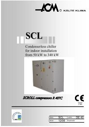
<strong>CD</strong> 30 ÷ 5203. View (one module 65kW)4. Principle of systemOne module (60KW) consists of 2 units (30KW); each unit has two entire refrigeration systems(system A and system B), which consist of two compressors and one plate heat exchanger.7
<strong>CD</strong> 30 ÷ 520Numbers of modules can be assembled into a large unit by connecting each own inlet & outletpipeline in series, a unit consists of 1-8 modules (2-16 units) and the max cooling capacity is 480KW,unit system of principle is shown as follows:To correctly operate the unit and ensure normal and safe running when the outdoor Temp isunder 0°C in winter, the following should be noticed:• If the unit will not be used for a long time, please drain water away to prevent the plate heatexchangerfrom freezing.• If it is used frequently, it is absolutely forbidden to switch off the power, because the unit hasauto anti-freeze function. Moreover, in order to protect the plate heat-exchanger from freezingin case the unit stops at night, and it must add some anti-freeze mixture to water system suchas glycol or propylene glycol.• Water flow switch should be installed correctly; otherwise, the unit may be damaged. What’smore, the water flow switch should be checked periodically if it is work normally.• If malfunctions occur, it is absolutely forbidden to turn on the unit before the problems aresolved. At the same time, please drain water away to prevent the plate heat-exchanger fromfreezing.8
<strong>CD</strong> 30 ÷ 5205. SpecificationCoolingModel<strong>CD</strong>30 60 90 120 150 180 210 240kW 30 60 90 120 150 180 210 240Capacity *1000 kcal/h 25.8 51.6 77.4 103.2 129 154.8 180.6 206.4HeatingkW 32 64 96 128 160 192 224 256capacity *1000 kcal/h 27.5 55 82.6 <strong>11</strong>0.1 137.6 165.1 192.7 220.2Cooling input kW 10 20 30 40 50 60 70 80Heating input kW 9.8 19.5 29.3 39.0 48.8 58.5 68.3 78.0PowerControl typeSafety protection device380V 3N~ 50HzWire controlHigh/low-pressure switch, anti-frost switch, water-flow switch, over-loadprotection, and power phases sequence protection.Main module + auxiliary module 1+0 1+1 1+2 1+3 1+4 1+5 1+6 1+7Water systemAir sideheat-exchangerDimensionCompressor input kW 9 18 27 36 45 54 63 72RefrigerantR407CRefrigerant kg 4.5*2 4.5*4 4.5*6 4.5*8 4.5*10 4.5*12 4.5*14 4.5*16Water flow volumem 3 /hWater resistance losskPaWatersideheat-exchanger5.2 10.3 15.5 20.6 25.8 30.9 36.0 41.218Welding, stainless steel, plate heat exchangerMax. Pressure MPa 1.0Water inlet/outletpipeline diameterTypeAir flow volume*10 3 m 3 /h133mmFin coil12 24 36 48 60 72 84 96Fan motor input kW 0.7*1 0.7*2 0.7*3 0.7*4 0.7*5 0.7*6 0.7*7 0.7*8L mm 1514W mm 850 2300 3450 4600 5750 6900 8050 9200H mm 1820Total weight kg 440 880 1320 1760 2200 2640 3080 3520Packing mm L×W×H(1620×1034×2041)Optional auxiliary heater kW 7.5 15 22.5 30 37.5 45 52.6 60* Noise level dB(A) 59,1 62,1 63,9 65,1 66,1 66,9 67,6 68,1* At 1,5 m from ground et distance of 1 mNotes:1.each module is packed separately and the packing size refers to one module only .2.Auxiliary electric heaters are not provided. If necessary,the users may refer to the abovetables parameter about auxiliary electric heater and configure themselves.9
<strong>CD</strong> 30 ÷ 520CoolingModel<strong>CD</strong>270 300 330 360 390 420 450 480kW 270 300 330 360 390 420 450 480Capacity *1000 kcal/h 232.2 258 283.8 309.6 335.4 361.2 387 412.8HeatingkW 288 320 352 384 416 448 480 512capacity *1000 kcal/h 247.5 275 302.5 330 357.5 385 412.5 440Cooling input kW 90 100 <strong>11</strong>0 120 130 140 150 160Heating input kW 87.8 97.5 107.3 <strong>11</strong>7.0 126.8 136.5 146.3 156.0PowerControl typeSafety protection device380V 3N~ 50HzWire controlHigh/low-pressure switch, anti-frost switch, water-flow switch, over-loadprotection, and power phases sequence protection.Main module + auxiliary module 1+8 1+9 1+10 1+<strong>11</strong> 1+12 1+13 1+14 1+15Water systemAir sideheat-exchangerDimensionCompressor input kW 81 90 99 108 <strong>11</strong>7 126 135 144RefrigerantR407CRefrigerant kg 4.5*18 4.5*20 4.5*22 4.5*24 4.5*26 4.5*28 4.5*30 4.5*32Water flow volumem 3 /hWater resistance losskPaWatersideheat-exchanger46.4 51.5 56.7 61.8 67.0 72.1 77.3 82.418Welding, stainless steel, plate heat exchangerMax. Pressure MPa 1.0Water inlet/outletpipeline diameterTypeAir flow volume*10 3 m 3 /h133mmFin coil108 120 132 144 156 168 180 192Fan motor input kW 0.7*9 0.7*10 0.7*<strong>11</strong> 0.7*12 0.7*13 0.7*14 0.7*15 0.7*16L mm 1514W mm 12450 13900 15350 16800 18250 19700 2<strong>11</strong>50 22600H mm 1820Total weight kg 3960 4400 4480 5280 5720 6160 6600 7040Packing mm L×W×H(1620×1034×2041)Optional auxiliary heater kW 67.5 75 82.5 90 97.5 105 <strong>11</strong>2.5 120* Noise level dB(A) 68,6 69,1 69,5 69,9 70,2 70,6 70,9 71,1* At 1,5 m from ground et distance of 1 mNotes:1.each module is packed separately and the packing size refers to one module only .2.Auxiliary electric heaters are not provided. If necessary,the users may refer to the abovetables’ parameter about auxiliary electric heater and configure themselves.10
<strong>CD</strong> 30 ÷ 520CoolingModel<strong>CD</strong>65 130 195 260 325 390 455 520kW 65 130 195 260 325 390 455 520Capacity *1000 kcal/h 55.9 <strong>11</strong>1.8 167.7 223.6 279.5 335.4 391.3 447.2HeatingkW 69 138 207 276 345 414 483 552capacity *1000 kcal/h 59.3 <strong>11</strong>8.7 178.0 237.4 296.7 356.0 415.4 474.7Cooling input kW 21.5 43 64.5 86 107.5 129 150.5 172Heating input kW 21 42 63 84 105 126 147 168PowerControl typeSafety protection device380V 3N~ 50HzWire controlHigh/low-pressure switch, anti-frost switch, water-flow switch, over-loadprotection, and power phases sequence protection.Main module + auxiliary module 1+0 1+1 1+2 1+3 1+4 1+5 1+6 1+7Water systemAir sideheat-exchangerDimensionCompressor input kW 18.5 37 55.5 74 92.5 <strong>11</strong>1 129.5 148RefrigerantR407CRefrigerant kg 4.5*4 4.5*8 4.5*12 4.5*16 4.5*20 4.5*24 4.5*28 4.5*32Water flow volumem 3 /hWater resistance losskPaWatersideheat-exchanger<strong>11</strong>.2 22.4 33.6 44.8 56.0 67.2 78.4 89.629.4Welding, stainless steel, plate heat exchangerMax. Pressure MPa 1.0Water inlet/outletpipeline diameterTypeAir flow volume*10 3 m 3 /h133mmFin coil24 48 72 96 120 144 168 192Fan motor input kW 0.7*2 0.7*4 0.7*6 0.7*8 0.7*10 0.7*12 0.7*14 0.7*16L mm 2492W mm 850 2300 3450 4600 5750 6900 8050 9200H mm 1820Total weight kg 700 1400 2100 2800 3500 4200 4900 5600Packing mm L×W×H(2612×1034×2041)Optional auxiliary heater kW 15 30 45 60 75 90 105 120* Noise level dB(A) 59,6 62,6 64,4 65,6 66,6 67,4 68,1 68,6* At 1,5 m from ground et distance of 1 mNotes:1.each module is packed separately and the packing size refers to one module only .2.Auxiliary electric heaters are not provided. If necessary,the users may refer to the abovetables’ parameter about auxiliary electric heater and configure themselves.<strong>11</strong>
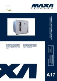
<strong>CD</strong> 30 ÷ 5203. surrounding Temp. of unit work is shown as follows:Name Cooling operation Heating operationWater-outlet temperature ≥3℃ ≤58℃Air-side heat-exchangerAir-inlet temperature17—43℃ -7—17℃6. Digital scroll compressorDigital scroll compressor is made up of following components: fixed vortex plate, movable vortexplate, motor, suction and discharge pipe、PWM(Pulse WidthModulation) solenoid valve and so on. It differs from ordinaryscroll compressor: the compressor utilizes the axial flexiblesealed technology and PWM solenoid valve to precisely adjustthe axial moving range of the stator scroll plate. And there is anadditional connecting bypass at the suction inlet connected withthe middle pressure bore at the floating sealed point of axialstator. When PWM solenoid valve is turned on, the pressure inmiddle pressure bore is released. The pressure in compressbore is higher than on the stator. The stator axis of thecompressor will move upward a little. So the unload is achieved.When the solenoid is turned off, the stator is pressed down. Then the seal and upload is achieved.The compressor plate can adjust the ratio of on and off freely to achieve the output of “0-1”, that isDigital Scroll Compressor.6.1 FlexibleThe stator and rotor can move axially and radial in certain space and can separate under normalcondition.6.2 Axial flexible sealedThere is about 1mm space for stator to move axially. Normally, under the action of gas pressure(discharge pressure and middle pressure of compressor chamber), the stator and rotator cancombine tightly and form the sealing surface.12
<strong>CD</strong> 30 ÷ 5206.3 Pulse width modulate (PWM)During half period of output voltage, the output voltage wave is divided into some pulse waves. Dueto the average output voltage and pulse duty ratio (pulse width dividing the pulse period is duty ratio)is direct ratio, when modulating the frequency, not change the pulse width but change the pulse dutyratio, thus realize variable frequency and variable voltage.6.4 Principle of Digital Scroll CompressorThe fixed vortex plate on the top is allowed to move upwards about 1mm during the operation of the Digital Scroll. Lifting the top vortexplate ensures that there is no pumping through the vortex plate, andthere is no mass flow through the compressor. This is the period ofzero capacity for the compressor. This state is called the “UnloadingState” of the compressor. The “Loading State” is the normal statewhen the scrolls are operating normally like a standard scroll and the capacity is 100%. It isimportant to point out that there is no bypass of gas in this operation. The principle of achievingmodulation is by alternately lifting and engaging the top vortex plate. A cycle time consists of a“Loading State” time and “Unloading State” time. The duration of these 2 time segment determinethe capacity modulation of the compressor.13
<strong>CD</strong> 30 ÷ 520Example: the total capacity is 10HP, cycle time is 20 seconds. If the output power is 5HP(50%oftotal capacity),the compressor modulation is(10 sec. × 100%+10sec. × 0%)/20sec.=50%. Theloading state time is 10 seconds and the unloading state time is 10 second. If the output power is2HP( 20%of total capacity),the compressor modulation is 20%, the state time is 4 sec. and theunloading state time is 16 sec.the rest can be deduced by analogy. The following is schematicdiagram when output capacity is respectively 10%, 50% and 100%.10℅Capacity output:2 Sec.2 Sec.2 Sec.18 Sec.18 Sec.18 Sec.One Period 20 Sec.50℅Capacity output:10 Sec.10 Sec.10 Sec.10 Sec. 10 Sec. 10 Sec.One Period 20 Sec.100℅ Capacity output:20 Sec.20 Sec.20 Sec.One Period 20 Sec.One Period 20 Sec.One Period 20 Sec.14
<strong>CD</strong> 30 ÷ 5207. The capacity control of the new modular chiller(1) Capacity adjustment of the system.Only the main unit can control the capacity output according to the temperature of total outputwater (Ts).1. Cooling capacity adjustmentPlease preset Ts (Ts=7,8,9,10,<strong>11</strong>,12℃). Ts is 7℃ in default.At first, the main unit will calculateδ1 (δ1=Ts-7), then adjust the capacity outputaccording to T(T=5,6,7℃)+δ1(T means the real temperature of total outlet water). Thedetail of cooling capacity adjustment is as following chart:TTsOFFCooling Regolazione capacity della adustment potenza di raffreddamento2. Heating capacity adjustmentPlease preset Ts (Ts=45,46,47,48,49,50℃), Ts is 45℃ in default.;At first, the mainunit will calculateδ2 =Ts-45,then adjust the capacity output according T(T=44,45,46,47,48℃)+δ2 (T means the real temperature of total outlet water). The detail of heatingcapacity adjustment is as following chart:Heating capacity adjustmentFor example:If the system have <strong>11</strong> sets of units, when T reduce to 45℃ in HEATING mode,15
<strong>CD</strong> 30 ÷ 520the system will operate on 80%. So the actual operation units are 9 sets. (<strong>11</strong>*80%=8.8,adopts9), and the main unit will stop two units which address is highest.(2) Capacity adjustment of every one unitTemperature of heat exchangerCooling adjustment capacity in ON/OFF modeTemperature of plate heat exchangerHeating adjustment capacity in ON/OFF modeTemperature of plate heat exchangerCooling capacity adjustment with digital control unitTemperature of plate heat exchangerHeating capacity adjustment with digital control unit16
<strong>CD</strong> 30 ÷ 5207.1. Heating and cooling capacity mod. 30 KwCooling capacityOutlet water temperaturePower inputOutlet water temperatureAmbient temp. °C 5℃ 7℃ 9℃ 12℃ 5℃ 7℃ 9℃ 12℃25 31.2 33.1 34.4 35.5 8.6 8.8 9 9.328 30.9 32.4 33.9 35.2 8.8 8.9 9.1 9.430 29.9 31.5 33 34.7 9.2 9.3 9.5 9.832 29.7 31.2 32.7 34.2 9.4 9.5 9.7 1035 28.5 30 31.8 33 9.7 10 10.3 10.538 27.6 29.1 30.6 31.8 10.3 10.5 10.8 10.840 27 28.2 29.7 31.2 10.6 10.8 <strong>11</strong>.1 <strong>11</strong>.1Cooling capacityKw3735333129275ºC7ºC9ºC12ºCThe diagram shows the capacityprogress among ambienttemperature and outlet watertemperature of 5°C, 7°C, 9°C,12°C2525ºC 28ºC 30ºC 32ºC 35ºC 38ºC 40ºCAmbient temperature12Power input in coolingKw<strong>11</strong>10985ºC7ºC9ºC12ºCThe diagram shows the powerinput progress among ambienttemperature and outlet watertemperature of 5°C, 7°C, 9°C,12°C725ºC 28ºC 30ºC 32ºC 35ºC 38ºC 40ºCAmbient temperature17
<strong>CD</strong> 30 ÷ 520Heating capacityOutlet water temperaturePower inputOutlet water temperatureAmbient temp. °C 39 42 45 48 50 39 42 45 48 5013 39.4 38.8 38.1 36.8 36.2 9.2 9.6 10 10.5 <strong>11</strong>.210 36.8 36.2 35.5 34.6 33.6 9.4 9.8 10.3 10.8 10.97 33.9 33 32 28.8 30.4 9.0 9.4 9.8 10.3 10.72 30.1 29.1 28.2 27.2 26.2 8.8 9.2 9.6 10 10.3-2 25.9 25 24 23.4 22.4 8.5 8.9 9.4 9.8 10.2-6 22.4 21.8 20.8 20.2 19.2 8.3 8.7 9.2 9.6 10-10 20.5 19.8 19.2 18.2 17.3 8.1 8.5 9.0 9.4 9.8Heating capacity40Kw3530252039ºC42ºC45ºC48ºC50ºCThe diagram shows the capacityprogress among ambienttemperature and outlet watertemperature of 39°C, 42°C,45°C, 48°C, 50°C1513ºC 10ºC 7ºC 2ºC -2ºC -6ºC -10ºCAmbient temperature12<strong>11</strong>10Kw9Heating capacity39ºC42ºC45ºC48ºC50ºCThe diagram shows the powerinput progress among ambienttemperature and outlet watertemperature of 39°C, 42°C,45°C, 48°C, 50°C8713ºC 10ºC 7ºC 2ºC -2ºC -6ºC -10ºCAmbient temperature18
<strong>CD</strong> 30 ÷ 5207.2. Cooling and heating capacity mod. 65 KwCooling capacityOutlet water temperaturePower inputOutlet water temperatureAmbient temp. °C 5℃ 7℃ 9℃ 12℃ 5℃ 7℃ 9℃ 12℃25 67.6 71.5 74.75 75.4 18.49 18.92 19.35 19.99528 66.95 70.2 73.45 76.70 18.92 19.135 19.565 20.2130 64.675 68.25 71.5 75.075 19.78 19.8875 20.3 21.032 64.4 67.6 70.9 74.1 20.21 20.4 20.9 21.535 61.8 65 68.9 71.5 20.9 21.5 22.1 22.638 59.8 63.1 66.3 68.9 22.1 22.6 23.2 23.240 58.5 61.1 64.4 67.6 22.8 23.2 23.9 23.9Cooling capacity807570Kw65605ºC7ºC9ºC12ºCThe diagram shows the capacityprogress among ambienttemperature and outlet watertemperature of 5°C, 7°C, 9°C,12°C5525ºC 28ºC 30ºC 32ºC 35ºC 38ºC 40ºCAmbient temperaturePower input25Kw232<strong>11</strong>95ºC7ºC9ºC12ºCThe diagram shows the powerinput progress among ambienttemperature and outlet watertemperature of 5°C, 7°C, 9°C,12°C1725ºC 28ºC 30ºC 32ºC 35ºC 38ºC 40ºCAmbient temperature19
<strong>CD</strong> 30 ÷ 520Heating capacityOutlet water temperaturePower inputOutlet water temperatureAmbient temp. °C 39 42 45 48 50 39 42 45 48 5013 84.9 83.5 82.1 79.4 78.0 20.2 21 22.1 23.1 23.910 79.4 78.0 76.6 74.5 72.5 19.7 20.6 21.4 22.5 23.37 73.1 71.1 69 67.6 65.6 19.3 20.2 21 22.1 22.92 64.9 62.8 60.7 58.6 56.6 18.9 19.7 20.6 21.4 22.1-2 55.9 53.8 51.8 50.4 48.3 18.3 19.1 20.2 21 21.8-6 48.3 46.9 44.9 43.5 41.4 17.9 18.7 19.7 20.6 21.4-10 44.2 42.8 41.4 39.3 37.3 17.4 18.3 19.3 20.2 2190Heating capacityKw8070605039ºC42ºC45ºC48ºC50ºCThe diagram shows the capacityprogress among ambienttemperature and outlet watertemperature of 39°C, 42°C,45°C, 48°C, 50°C403013ºC 10ºC 7ºC 2ºC -2ºC -6ºC -10ºCAmbient temperatureKw25232<strong>11</strong>917Power input39ºC42ºC45ºC48ºC50ºCThe diagram shows the powerinput progress among ambienttemperature and outlet watertemperature of 39°C, 42°C,45°C, 48°C, 50°C1513ºC 10ºC 7ºC 2ºC -2ºC -6ºC -10ºCAmbient temperature20
<strong>CD</strong> 30 ÷ 5207.3 Principle of Digital Scroll CompressorScroll system controls refrigerant output by the ratio of loading and unloading time of compressor,and adjustment of loading time could be “stepless”. Furthermore, no need to change speed, and noneed to worry about lubrication failures, which realizes the wide-range capacity adjustment ofcompressor. This can save the transformer cost and consumption, decrease the interference ofhigher harmonic wave upon power transmission system, enlarge the work condition range ofcompressor.Summuruzing: Widen capacity range from 10% to 100%; Stepless energy adjustment with higher SEER and lower energy consumption; The PWM solenoid valve can be used 40 million times on average, about 30 years; High reliability and compressing ratio by utilizing axial flexible sealing technology; Outstanding SEER approved by JIS and ARI; With the unique flexible technology, remarkably enhancing the abilities of anti-liquidpumping and anti-rubbing, which can prevent the compressor from liquid pumping in mostof cases; Free of electromagnetic disturbance; Free of additional oil recycling equipment, achieve longer pipeline and higher dropdifference design.8. Features• Easy assembling Each module has independent structure, protect function, refrigeration system, powersupply and control system. When some problems occur in one of unit (auxiliary unit),others can keep running normally. Unit can be assembled by variable modules (up to 8) according to different capacityrequirement and the capacity can reach to 480kW (8×60kW). Modules can be installed closely or within a certain distance according to differentspace requirement. Compact structure, easy maintenance.21
<strong>CD</strong> 30 ÷ 520 Simple and elaborate structure module design, reasonable pipeline arrangement, andgood effect. Opening module structure design is beneficiary for the air flowing into condenser andmaintenance.• Easy control, energy saving When unit is running, the controller can automatically adjust each module’s capacityoutput or turn on, shut down the corresponding modules according to the systemrequirement. Each unit applies dual compressors that can achieve the best effect of energy savingby further elaborated adjustment. Micro computer controller can ensure the system running with high efficiency by theauto control functions such as intelligent defrosting, problems analyzing, energymanagement, anti-freeze inspecting and running mode, etc.• Orderly starting, intelligent memorizing When unit turns on, the controller can automatically start corresponding modulessuccessively according to actual capacity requirement. The controller can automatically store start sequence and running hours of eachmodule, so if running hours of one module has reached the pre-set standard, systemwill shut off this module, and start another. The module with shorter time to energize willbe turned on first in the next operation, so it can be achieved to make a balance amongmodules to extend the life of system.• Remote & internet control. Each unit has one electric control system, which can accomplish independently thesuch functions as order input, control output, trouble solving, protection, etc. The communication between system and human can be achieved by linear controller,which can receive the customers’ operation orders and send them to main controller, aswell as collect the running data and display them on the screen.22
<strong>CD</strong> 30 ÷ 520 Matched RS485 communication interface achieve the remote monitoring function,furthermore it can be connected to Internet by using the reserved computer interface.9. Unit installation• Transportation Be sure that the package will be transported safely, unpack until arrive at installation site The leaning angle during the transportation should be smaller than 15 degree to preventthe module from rolling over. When transporting the module with rolling bars, it is recommended to use 6 bars under themodule, each one should be a bit longer than the width of basement to keep the module’sin balance. Sling the module with steel wire, be sure that the wire could bear the weight 3 timesheavier than that of the module, and check whether if it hooks to module tightly. Thehanging angle should be bigger than 60 degrees.Notice: it is absolutely forbidden to stand under the module while hanging, please use softboard to protect the module surface which contact the steel wire from scratch anddistortion.23
<strong>CD</strong> 30 ÷ 520Protect Board• Required installation places Clean, bright and well ventilated place such as roof, balcony or courtyard. Places without the interference of lampblack, steam and other kind of heat source. Places where it is convenient for pipeline installation and water draining with the leastinfluence to surroundings, which is caused by noise and cool or heat wind. Places close to electric power. Places with solid basement to prevent noise and vibration. Ensure there is sufficient space for maintenance, and the required room is shown as follow.Check if there are any barriers that may block the airflow. The wall around the moduleshould be not higher than 1m (from the bottom of module). It is recommended to cover themodule to prevent from raindrop and snow, but the space between the cover and the top ofmodule should be more than 2m.>1.2m>1.2m>1.2m >1.2m When installing modules in parallel, it is suggested to leave sufficient space amongmodules for maintenance.24
<strong>CD</strong> 30 ÷ 520• Installation foundation Before installation, it should consider the structure and prefabrication of the basement,especially when installing. When stalling on the top floor or middle, the floor intensity and noise preventing should beconsidered. It is preferable to communicate with building designer before installation. The drainage channel must be made around the basement to ensure the water can bedrained away fluently. In order to avoid the vibration and noise caused by module, a pad must be set between themodule and the basement to reduce vibration. Moreover, the module should be installedon the plane, and a shockproof basement can be adopted if necessary. It is recommended to take some measures to prevent the movement caused by long-termrunning, earthquake or typhoon.• Installation referenceThe installation basement for main module is shown as follows; the auxiliary module is thesame as the main one. 60mm distance should be left between modules. The weight that theconcrete can support should be 1.5 to 2 times of the weight of modules when the modules areinstalled on the ground.10. Water system installationEvery pipeline’s joint has marks of water-outlet and water-inlet mark. The following should benoticed when connecting pipelines:• The water passage is narrow due to the adoption of plate heat exchanger, so it is easilyjammed by particles or dust, which may cause freezing and damage the system. To prevent thisproblems, the users should try to install a Y shape filter with 20 item reticulation at the inlet of25
<strong>CD</strong> 30 ÷ 520chilled-water or cooled-water near the module.• The water pipeline should be cleaned before connecting to the unit, then dismantle the filter andinstall again. After confirming the water pipeline is clean, the connection can be done.• The soft connector should be used at the inlet (outlet) water pipe to avoid vibration.• To ensure turn on the water pump first and then the unit, the water switch should be installed onthe inlet pipeline and connect its wire to terminal W1 and W2 of main unit.• Water discharge switch should be installed at the outlet pipe, and gas discharge valve shouldbe installed at the inlet water pipe. When the unit works normally, the handler of valve must betaken away to ensure the valve can’t be opened. If the water discharge valve is opened whenthe unit is running, water breaking-off will occur.• The freeze-water pipeline should be covered with adequate heat-insulating material to keep thechilled-water temp. and prevent dewing.• In the cold winter, if the unit stops at night, the water in plate heat exchanger and pipeline mayfreeze, which will damage the device and pipeline. To prevent freezing, it is absolutelyforbidden to switch off the power of the unit (the unit has auto anti-freeze function). If it is stilllikely to freeze, it must drain away all water in the water pipe. If it is difficult to drain water, someanti-freeze mixture such as glycol or propylene glycol can be adopted. Notice: it is absolutelyforbidden to use salt mixture, which would corrode the system and cause damage.• When using industrial water as chilled-water, it seldom scales. However if adopting the waterfrom well or river, it will produce much deposit such as scale and sand. So the water shouldbe filtered and intenerated through some equipment before flowing into the freeze-watersystem. If there is sand or mud deposited in the evaporator, it will jam the flow of chilled-water,which will cause freezing. So it is important to test the water’s PH value, conductivity,concentration of chlorine hydronium, concentration of sulfur hydronium, etc.The following is the standard of water quality:PH value: 6.5~8.0 Total rigidity:
<strong>CD</strong> 30 ÷ 520<strong>11</strong>. WiringAll wiring installation must be done by qualified person.Precautions:• The power supply must be stable when the unit is running. Considering all voltage-drop factors,the running voltage needed by the system should be kept within ±10% range of the rating.Too high or too low voltage will have bad effect on the unit.• The difference of voltage among phases should be not more than 2% of the rating, and themax current difference among phases should be less than 3% the rating to prevent compressorfrom overheating.• The frequency of the power should be kept within ±2%of the rating.• The lowest starting voltage should be more than 90% of the rating.• The compressor may be unable to start if the wire is too longer, so the length of the wire shouldbe limited to ensure the voltage-drop between the two ends of the wire is less than 2% of therating. If it is unavailable to shorten the wire, thicker wire is available.• All wire must conform to concerning national standards and well insulated. The insulationbetween terminals and modules should be checked by 500v high resistance meter and itsinsulation resistance should be not less than 10 MΩ.• For safety, according to the concerning standards, unit should be grounded well to preventelectric shock.• The running current, input power and other parameters on the nameplate might be differentfrom the actual situation, which is decided by the actual load and cooling water temp., so it isrecommended to select power source, transformer, fuse switch and the size of the wire in theconsideration of the worst condition.• In order to control the compressors conveniently as well as independently and avoid thedamage caused by the short circuit, it is necessary to equip the suitable no-fuse air switch foreach inlet wire.27
<strong>CD</strong> 30 ÷ 520• One module consists of two units, each unit’s main power should be wired independently andthe detail is shown as follow:The minimal diameter Of wire(mm 2 )Hand switchModelItemsPower(metal tube, vinylite)Power wire(
<strong>CD</strong> 30 ÷ 52012. Debugging• PreparationAfter cleaning the water system pipeline for several times, ensure the water is clean, thenpump and drain again, and start the pump to ensure the flow and the pressure of inlet and outletpipeline is qualified.Notice: the water pump is under the control of the main unit, so when the water system isrunning, it can make the control circuit of water pump AC contactor electrify by temporarilywiring, thus to make the water pump running.Warning: it is absolutely forbidden to start the pump by the control of main unit before the watersystem has been adjusted well. Please set the address switch on the unit controller according to the rule below.Warning: address switch setting must be done without any electric supply and when the unit iselectrified, setting is absolutely forbidden.29
<strong>CD</strong> 30 ÷ 520Unit address settingCorresponding table betweenaddress code and unit address• 0presents NO. 0 main unit,1~F inturn presents NO 1 ~ 15 auxiliaryunits.(respectively)• One module consists of two units, sothere are two addresses for eachmodule.• Address of each unit should not berepeated; otherwise modules wouldbe unable to start due to protection.So it must set the switch to differentaddress code.Address Unit addresscode0 NO. 0 main unit1 NO. 1auxiliary unit2 NO. 2 auxiliary unit3 NO. 3 auxiliary unit4 NO. 4 auxiliary unit5 NO. 5 auxiliary unit6 NO. 6 auxiliary unit7 NO. 7 auxiliary unit8 NO. 8 auxiliary unit9 NO. 9 auxiliary unitA NO. 10 auxiliary unitB NO. <strong>11</strong> auxiliary unitC NO. 12 auxiliary unitD NO. 13 auxiliary unitE NO. 14 auxiliary unitF NO. 15 auxiliary unit Digital scroll modular and Normal scroll modular can be selected according to DIGITswitch.Notice: the DIGIT switch has been set well in the factory and needn’t change.“00” presents to selectdigital compressor (as themain unit.)“<strong>11</strong>” presents to selectconstant compressor (asthe auxiliary unit.)30
<strong>CD</strong> 30 ÷ 520 Please turn on the main power 12 hours before staring to preheat the compressor. If thecompressor is not preheated enough, it maybe damaged. Adjust carefully the water flow switch on water system or close valve at inlet to ensure thewater flow volume is 90% of the rating. Check if any component of the unit is loose and the unit has no distortion and rupture. Before starting, please check carefully if the power voltage and wiring are right. Check ifthe power sequence is correct. If not, it needs to exchange. Check if the connecting part istight and fasten once again. Connect the water flow switch correctly to the control cycle. Put the Temp. sensor to the right position, and then fasten it well to prevent from falling off.• Testing Turn on the unit by wire controller. If there is ERROR Code displayed, please firsteliminate the malfunction; confirm there is no malfunction before restarting. After 30 minutes, when the temp of water is stable, adjust the water flow volume tonominal value to ensure the unit running normally. When the unit is working, check the Running Current, Running Pressure, Water Pressure,Water flow Volume, Water Temp. Difference between inlet and outlet water, What’s more,adjust the water flow volume according to the actual conditions to ensure the unit runningnormally. Optimizing the setting parameters according to the local weather and concerningoperation references. After the unit stops, start the unit 10 minutes later to prevent the unit from startingfrequently. Check if the control and protection devices are normal according to thefollowing table:31
<strong>CD</strong> 30 ÷ 520For compressorModelsHigh-pressureswitchCut offCloseLow-pressureswitchCut offCloseTemp Sensor inside thedigital compressorMPaMPa-<strong>CD</strong>60 120 180 240 300 360 420 480Reset automatically,unadjusted3.32.4Reset automatically,unadjusted0.030.15Controlled by micro- controllerWhen the Temp. is lower than 125℃, compressorwill not work. When the Temp. is higher than 125℃, the capacity output of digital compressor willdecrease to 40%. When the Temp. is higher than140℃,compressor will stop. After the malfunctiondisappear, compressor will restart 3 minutes later.Over-current protection A 18Heating beltEach compressor has oneWCapacity40Discharge Temp.Protection130℃Cut off90CloseAnti-freeze ProtectionSwitch℃Controlled by micro- controller (one every cycle.)3• Notices Because the water pump is under the control of main unit, it is forbidden to start the pumpby the main unit when cleaning water system pipeline. Before finishing draining water out from pipeline, it is forbidden to start unit. Install the water flow switch correctly; otherwise water shortage accident will happen. During test-running, do not restart the unit by manual in 4 minutes after the unit stops. In the season when the unit needs to be frequently used, don’t switch off power after theunit stops. Otherwise, the compressor can’t be preheated, which may damage thecompressor. After a long time without electrifying, please pre-electrify the unit 12 hours in advance topreheat the compressors.32
<strong>CD</strong> 30 ÷ 52013. MaintenanceTo ensure the unit can reliably run for a long time, debugging and maintenance should be doneby the qualified persons. The items below should be noticed especially.• Warning If it is on fire, switch off the main power at once and eradicate the fire with extinguisher. The unit can’t be operated near the flammable gas to prevent fire or explosion.• Caution Maintain unit regularly according to the reference to keep unit in a good condition. Do not touch the discharge pipeline to avoid any scald. If malfunction causes the unit stop, please refer to the “Troubles and solutions” part of thismanual or contact with us to find out the reason. After the malfunction is eliminated, theunit can be restarted again. It is absolutely forbidden to forced restart the unit withoutsolving the problems. If refrigerant or chilled water (cooling water) has leakage, it mustshut down all switches. If the unit can’t be stopped by the controller, it must switch off themain power to stop the unit. Do not use any iron wire, copper wire instead of the demanded fuse, otherwise it willcause the fire and damage the system. Don’t make the protection device short-circuited, otherwise it may cause accident.• Maintenance for main components During running, please notice the discharge pressure and suction pressure. If there isanything abnormal, please find out the reason and eliminate the malfunction. Don’t adjust the control and protection devices at random. Check the wire connection regularly to confirm there is no any loose or bad contact causedby oxidation or other reasons. Please frequently check the work voltage, current andphases balance. Check the reliability of the electric components, and replace the invalid and the unreliablein time.• DescalingAfter a long term running, the surface of the heat exchanger of waterside will form calciumoxide and other mineral. Those kinds of material will decrease the heat transfer efficiency, causemore power consumption and higher discharge pressure (or lower suction pressure). Thesematerials can be cleaned by formyl, citric acid, vinegar acid, etc, but any liquid which containschlorine acid or fluoride ingredient is forbidden. Because the pipe is made of stainless steel, it iseasy to be rotted by such material.33
<strong>CD</strong> 30 ÷ 520 Cleaning work of waterside heat exchanger should be operated by the professional,please contact with our local MAXA service center. After cleaning by chemical liquid detergent, scour the pipeline with clean water and heatthe exchanger again. Pre-dispose the water to avoid rotting and forming of the scaleagain. On the condition of using chemical liquid detergent, please select the intensity, cleaningtime and Temperature of the liquid according to the actual situation. After cleaning, the waste liquid should be neutralized, so please contact the professionalcompany to get the further disposal for the waste. Detergent and neutralization liquid are harmful to human beings, so it is necessary to usesome protective device, such as special glasses, gloves, shoes, mask, etc.• Turn off the unit in winterWhen turning off the unit in winter, clean and dried the inner and outer surface of the unit, thencover them to prevent dust. Open the water discharge valve, drain away the water in heatexchanger of water side and water pipe to prevent freeze. It is recommended to inject someanti-freeze material into the water pipe.• First start after the unit stopsThe following must be done when restarting the unit after a long-term vacancy: Check and clean unit thoroughly. Clean the water system pipeline. Check water pump, adjust switch and other devices of the water system. Tighten all the wire connections.• Accessory replacementOnly MAXA accessory can be used and please don’t use any different one.• Refrigeration systemCheck the discharge and suction pressure to determine whether the unit needs to recharge or not.Take leakage test for the system; if there is leakage or some components needs to be replaced,leakage test is necessary. When recharging refrigerant, two cases must be separated: The refrigerant has leaked out totallyIn this case, leakage test must be done by using nitrogen (15~20 kgf/cm 2 ) or refrigerant. Ifnecessary, welding should be done after all gas of the system is discharged out.1) Connect the vacuum pump pipeline to the refrigerant charging hole.34
<strong>CD</strong> 30 ÷ 5202) Vacuum refrigerant pipeline more than 15 minutes and confirm it achieve -1.0×10 5 Pa(-76cmHg).3) After having achieved the designated vacuity, add refrigerant to the system from thecylinder, corresponding volume of the refrigerant can be got from the nameplate andparameters table. It should be noticed that charging just be allowed from the liquidpipeline side.4) The volume charged into the system will vary from different surrounding Temperature,if the designated volume can’t be achieved, unit can be started for recharging whilethe water system is running. Wire the low-pressure switch to short circuit if necessary.Notice: rewiring the connection after charging. Additional refrigerant chargeConnect refrigerant cylinder to the refrigerant charging hole and mount a pressuredetector on the gas side pipeline.1) Recycle the chilled-water, then start unit, take low-pressure control switch to shortcircuit if necessary.2) Charge the refrigerant into the system slowly, and check the discharge and suctionpressure.Warning: it is absolutely forbidden to charge the oxygen, acetylene or other gaswhich is poisonous or flammable into the system for leak hunting or leakage test,just nitrogen or refrigerant is allowed.35
<strong>CD</strong> 30 ÷ 520• Remove compressorIf it is necessary to remove the compressor, please operate with the sequence below:1) Switch off the power2) Remove the electric wire3) Remove the suction and discharge pipeline4) Loosen the fixing bolts.5) Remove the compressor.• Auxiliary electric heaterWhen the outdoor Temperature (is)below 0℃, the condenser outside will frost, which will causethe heat transfer efficiency come down, for the reason above, when using unit in the areas wherethe lowest Temp is between -10℃~0℃ in the winter, it is recommended to select the auxiliaryelectric heater to supply the additional heat. Select the heater with the reference of “SpecificationTable”, if the Temp below -10℃, the higher power-input can be selected.• System anti-freezeIf plate heat exchanger is frozen, the exchanger will be damaged; in addition, this kind ofdamage is out of guarantee, so it should be specially noticed. Users should pay special attention tothe three points below: When there is a long-term vacancy with low outdoor TempWater in waterside heat exchanger should be drained out if the Temp below 0℃. When runningIf the chilled-water flow switch and anti-freeze Temp Sensor are invalid, water pipeline willbe frozen, so the wire of water flow switch must apply to the “wiring principle figure” When maintainingIt is possible to freeze waterside heat exchanger when recharging and dischargingrefrigerant. Whenever the pressure of the refrigerant is below 0.4Mpa, freezing wouldhappen. So it is necessary to drained out all of the water or keeps the water flowing.36
<strong>CD</strong> 30 ÷ 52014. Troubles and solutionsTroubles Possible reasons SolutionsAir or other gas enter the system Discharge the gas from refrigerantcharging hole, re-vacuuming ifFins are dirty or jammed by someobstaclesnecessaryClean the fins of condenserHigh discharge The condenser wind flow ispressure(Cooling)insufficient or motor failHigh suction pressureRefrigerant over-chargedHigh surrounding TempCheck the condenser motor, repair itif necessaryRefer to the “high suction pressure”part.Discharge the additional refrigerantMeasure the surrounding TempLow dischargepressure(Cooling)Surrounding Temp is lowerRefrigerant leak or insufficientLow suction pressureMeasure the surrounding TempLeak hunting or rechargingRefer to the “low suction pressure”High suctionpressure(Cooling)Refrigerant over-chargedHigh Temp of the inlet chilled-waterDischarge the additionalCheck the heat insulation of waterpipelineInsufficient of water flowMeasure the Temp differencebetween inlet and outlet water, adjustLow suctionLow Temp of inlet chilled-water the water flowpressureRefrigerant leak or insufficient Check installation(Cooling)Scaling in the evaporatorLeak hunting or rechargingDescalingWater flow InsufficientMeasure the Temp differencebetween inlet and outlet water, adjustAir or other gas enter the system the water flowDischarge the gas from refrigerantHigh dischargeScaling in the heat exchanger of charging hole, re-vacuuming ifpressurewatersidenecessary.(Heating)High Temp of outlet cooling water DescalingHigh suction pressureCheck the water TempRefer to “high suction pressure” part37
Low dischargepressure(Heating)High suctionpressure(Heating)Low suctionpressure(Heating)Compressor stopby anti-freezeprotection(Cooling)Compressor stopby High-pressureprotectionCompressor stopby the overloadprotectionCompressorstops by the innerTemp sensor orhigh dischargeTemp protection.Low Temp of cooling waterRefrigerant leak or insufficientLow suction pressureHigh surrounding TempRefrigerant over-chargedRefrigerant insufficientAir flow insufficientShort cycle of air flowDefrosting insufficientChilled-water insufficientAir enter the water systemfailure of the heat-sensitiveresistanceHigh discharge pressureHigh-pressure switch failureHigh-pressure both of dischargeand suctionHigh or low voltage, single phase orunbalance of the phasesshort circuit of the motor orterminalsOver-load component failureHigh or low voltageHigh discharge pressure or lowsuction pressureComponents failure<strong>CD</strong> 30 ÷ 520Check the Temp of cooling waterLeak hunting or rechargingRefer to “low suction pressure” partMeasure the surrounding TempDischarge the additionalRechargingCheck the running direction of the fanFind the reason caused short cycle,then eliminate itfour-ways value or heat-sensitiveresistance failure, replace them ifnecessaryFailure of the water pump or waterflow switch, maintain or replace themif necessaryDischarge the airIf failure confirmed, replace it.Refer to “high discharge pressure”If failure confirmed, maintain orreplace it if necessaryRefer to “high discharge pressure” or“low suction pressure” parts.Check the voltage which shouldnever exceed or below 20V to therating.check the motor and thecorresponding resistance of theterminalsReplace itCheck the voltage which shouldnever exceed or below 20V to therating.Refer to “high discharge pressure”and “low suction pressure” parts.38
<strong>CD</strong> 30 ÷ 520Compressor stopby thelow-pressureprotectionFilter jammed before (or after)electric expansion valveLow-pressure switch failureLow suction pressureCheck the inner Temp sensor, whenthe motor is coolReplace filterIf failure confirmed, replace it.Refer to “low suction pressure” part.Abnormal noisecause bycompressorOther abnormalnoiseCompressor can’tstartAirside heatexchangerover-frostedCompressor liquid pumping causedby the entrance of liquid refrigerant.Compressor agingPanel bolt loosedInsufficient strength of theinstallation foundation.Current relay open, burning thefuse.Open circuit of the control wireHigh or low-pressure protectionContactor wire burn outWrong phases sequenceWater system failureFailure code displayed by the linearcontroller.Four-ways value or heat-sensitiveresistance failure.Short cycle of the air flowAdjust the refrigerant volumeCheck expansion valve and suctiongas degree of superheat.Replace compressorFix all componentsRefer to “Unit installation ” partReplace the invalid componentsCheck the control system connectionRefer to the parts above about thefailures caused by suction anddischarge pressureReplace the invalid componentsExchange any two of three phaseswith each other.Check water systemConfirm the type of failure and takethe corresponding measure.Check the system, replace them ifnecessaryCheck the system; eliminate thefailure causing short cycle.39
<strong>CD</strong> 30 ÷ 52015. Electric control figure (main unit)2??effect ON no.0 module??1 2NORM<strong>AL</strong>ONPTC HEATER PUMPON<strong>11</strong> 2DIGIT<strong>AL</strong> TUNESWITCH FUNCTIONP Q (E)2-WAY JUMP SWITCH FUNCTIONH1 H2 P1 P24-WAY TERMIN<strong>AL</strong>Xt4BLACKYELLOWGRAYGRAY GRAY3-WAY TERMIN<strong>AL</strong> 3-WAY TERMIN<strong>AL</strong>Xt2Xt3S<strong>11</strong>6-WAY DI<strong>AL</strong> SWITCH FUNCTIONBLUEBLUEYELLOWORANGEBLACKREDBLUEBLACKHeatCn7PumpCn9Cn<strong>11</strong> BLACKCn15 WHITEBLUEYELLOWComp(b) s.v(b) Comp(a) s.v(a)Fan_h Fan_lry7 ry8PwmCn17PWM(A)Cn1 WHITEPMV(a)PWM(B)Cn2 REDPMV(b)ELECTRIC EXPANSIVE V<strong>AL</strong>VE(B)Plate heat exchanger freezeproofprotection sensorCn3 REDwater_proT62Cn22tbh1Cn18(WHITE)powerPlate heat exchanger freezeproofprotection sensorT61Cn21tbh2LOW pressureprotector BCn19 WHITEtrans outCn5h&l_proLow pressureprotector A PURPLECn6 Cn8 Cn10 Cn12 Cn13 Cn14ONCom(i) Com(o)WHITE RED WHITE T3A T3B T41 2S1S2QUERYCt1curRent(a)Ct2curRent(b)REDHigh pressureprotector BRt7 XP5XP6XP7XP8XP9ORANGETemp protectorswitch AHigh pressureprotector AXS5XS6XS7XS8XS9YELLOWRt5T3AT3BT4CONDENSER TEMP BCONDENSER TEMP A OUTDOOR TEMP SENSORTBRED BLACK WHITEPOWER380V 3N~50HzREDWHITEBLUEBLACK5-WAY TERMIN<strong>AL</strong>XT1A B C NREDWHITEBLUEREDBLUEWHITEBLACKBLACKFAN MOTORFANY&GHIGH LOWKM1 KM2BLUEWHITEREDRELAY RELAYFAN CAPMIDDLEWIRE JOINTXt8HEAT_ACRANKREDREDWHITEBLUEREDREDA1 A2 BLACKT2 T<strong>11</strong>234COMP562122AC CONTACTORBLUET3COMP AREDBLACKA1 A2 T2 T<strong>11</strong>2WHITE34BLUE 56COMPRED 2122AC CONTACTORT3COMP BY&GMIDDLEWIRE JOINTXt7Y&GPURPLEBLUEMIDDLEWIRE JOINTBLACKPWM PRESSURERELIEF VAVLEBLACKBLACKS.V(A)4-V<strong>AL</strong>VE AS.V(B)4-V<strong>AL</strong>VE BXt5 Xt6Y&G40BLACK
<strong>CD</strong> 30 ÷ 52016. Electric control figure (auxiliary unit)BLACKFAN MOTORBLUEHIGH LOWWHITE REDKM1 KM2RELAY RELAYFAN CAPCRANKREDREDWHITEBLUEREDA122AC CONTACTORREDA2 BLACKT2 T1BLUE T3BLUES.V(A)4-V<strong>AL</strong>VE AREDWHITE5-WAY TERMIN<strong>AL</strong>XT1REDWHITEBLUEBLACKPOWERFANY&GHEAT_A246135CONDENSER TEMP BCONDENSER TEMP A OUTDOOR TEMP SENSORTBRED BLACK WHITEBLACKBLUEWHITERED21COMPY&GCNBAMIDDLEWIRE JOINTXt8COMP A3BLUE 5REDA1 A2 BLACKT2 T<strong>11</strong>2WHITE46COMPRED 21 22T3COMP BAC CONTACTORY&GMIDDLEWIRE JOINTXt7BLACKPURPLEBLACKBLUEMIDDLEWIRE JOINTS.V(B)4-V<strong>AL</strong>VE BPWM PRESSURERELIEF VAVLEBLACKXt5 Xt6Y&G380V 3N~50HzBLACKT4T3BT3ARt5YELLOWXS9 XP9XS8 XP8XS7 XP7XS6 XP6High pressureprotector ATemp protectorswitch AORANGEHigh pressureprotector BREDCt2curRent(b)Ct1curRent(a)Cn6 Cn8 Cn10 Cn12 Cn13 Cn14ONCom(i) Com(o)WHITE RED WHITE T3A T3B T41 2Cn5S1h&l_proS2QUERYPURPLELow pressureprotector ACn19 WHITEtrans outLOW pressureprotector BCn21tbh2T61Plate heat exchanger freezeproofprotection sensorCn18(WHITE)powerCn22tbh1T62Cn3 REDwater_proPlate heat exchanger freezeproofprotection sensorELECTRIC EXPANSIVE V<strong>AL</strong>VE(B)Cn2 REDPMV(b)PWM(B)Cn1 WHITEPMV(a)PWM(A)PwmCn17Fan_lry8Fan_hry7Comp(b) s.v(b) Comp(a) s.v(a)YELLOWBLUECn15 WHITECn<strong>11</strong> BLACKPumpCn9HeatCn7BLACKBLUEREDBLACKORANGEYELLOWBLUEBLUE16-WAY DAIL SWITCH FUNCTIONS13-WAY TERMIN<strong>AL</strong>Xt33-WAY TERMIN<strong>AL</strong>Xt2GRAYGRAYBLACKYELLOWGRAY4-WAY TERMIN<strong>AL</strong>Xt4H2 P1 P2H12-WAY JUMP SWITCH FUNCTIONP Q (E)SWITCH FUNCTIONREDDIGIT<strong>AL</strong> TUNEON<strong>11</strong> 2(NOTE:XT3, XT4 EMPTY)NORM<strong>AL</strong>ON21 241
2<strong>CD</strong> 30 ÷ 52017. Unit electric control & communication figure for 30KW unitThe length of wireshould be shorterthan 500mLa lunghezza del cavodeve essere inferiorea 500mBlackYellowGrayNote: The wiring diagram of auxiliary heater is justfor reference,please follow the instructions ofcorresponding auxiliary heater products. Pleasechoose such accessory as power wire, switch ofwater pump and auxiliary heater according to theactual parameter of products and national standardsThe wiring terminal P,Q,and E on the back ofWire Controller are corresponding to theTerminal P,Q, and E of Wiring Board in MainModuleOThe metal plate of contactor installation boxshould be grounded42
18. Unit electric control & communication figure for 65KW unitBlackYellowGrayNote: The wiring diagram of auxiliary heater is justfor reference,please follow the instructions ofcorresponding auxiliary heater products. Pleasechoose such accessory as power wire, switch ofwater pump and auxiliary heater according to theactual parameter of products and national standardsThe wiring terminal P,Q,and E on the back ofWire Controller are corresponding to theTerminal P,Q, and E of Wiring Board in MainModuleOThe metal plate of contactor installation boxshould be grounded2
<strong>CD</strong> 30 ÷ 52019. Installation system figure44
<strong>CD</strong> 30 ÷ 520Unit electric controller1. Outlook view<strong>11</strong> 10 9 8 7 6 5 4 3 2 <strong>11</strong>21314151627262517 18 19 20 21 22 23 24Notice:• FailureWhen main unit fails, the unit stops as well as the others stop too.When auxiliary unit fails, this unit stops while the others keep running.• ProtectionWhen main unit’s protection acts, the unit stops while the others keep running.When auxiliary unit’s protection acts, this unit stops while the others keep running.2. Components description1——Compressor B current detection (Protection code P5)2——Compressor A current detection (Protection code P4)45
<strong>CD</strong> 30 ÷ 520The current will not be detected at the first 5 seconds when starting, after that, if the current isexceeds the pre-set protection standard, (18A for both of digital and constant), compressorwill stop, and restart 3 minutes later.3——T4: Outdoor Temperature sensor (failure code E7).T 3B : Condenser B tube Temperature sensor (failure code E6, protection code P7).T 3A : Condenser A tube Temperature sensor (failure code E5, protection code P6). T4If any one system needs to start the outdoor fan, the fan will be started by the unit electriccontroller. The fan has two speed levels: high and low which all depends on the T4Temperature. T 3B 、T 3A When unit electric controller detects the Temperature of T 3B or T 3A are higher than 65℃,the corresponding system will stop, then restart after the Temperature is lower than 60℃or less. Meanwhile the other system keeps running without any influence. T4、T 3B 、T 3AThe alarm will work if the voltage detected by the Temperature sensor is less than 0.05V ormore than 4.95V.• If main unit sensor of fails: all units will stop.• If auxiliary unit sensor fails: this unit will stop while the others keep running.4——System A compressor discharge gas Temperature sensor (failure code E8,protection code P8) is only available for main unit.5——Outlet water Temperature sensor of plate heat exchanger (failure code E4).Capacity output will adjust according to the outlet water Temperature of the plate heatexchanger both in cooling and heating models.(Auxiliary unit) constantly adjusting range: ON and OFF;(Main unit) digitally adjusting range: OFF, 40%, 60%, 80% and 100%.6——Total outlet water Temperature sensor (failure code E3), just valid for main unit.Adjust the Capacity output adjustment according to the outlet water Temperature of theplate heat exchanger both in cooling and heating modesAdjusting range: OFF, 40%, 60%, 80% and 100%.7——CHECK It can be achieved by CHECK to observe the running condition of the outdoor46
<strong>CD</strong> 30 ÷ 520systems. The corresponding data will be shown as follows:Normal displayRunning modelB compressorcapacityOn line modulesAmbienttemperatureCondenser AtemperatureA system running currentExv B liftExv A liftCondenser Btemperature8——DIGIT Digital compressor selecting switch.“00” presents selectingdigital compressor (asthe main unit.)“<strong>11</strong>” presents selectingconstant compressor (asthe auxiliary unit.9——ADDRESS0 presents NO. 0 mainunit1~F presents NO 1~15 auxiliary unitsrespectively10——COM(O)485 communication port (failure code E2).<strong>11</strong>——COM(I) 485 communication port (failure code E2).P, Q, E points of COM (O) and COM (I) are connected with each other for RS-485communication. If failure occurs between the linear controller and main module, all the units stop.47
<strong>CD</strong> 30 ÷ 520 If failure occurs between main unit and auxiliary unit, the auxiliary unit withcommunication failure will stop, and then the number of units online detected by thelinear controller will decrease; ”EA” will be displayed and the indicator lights will flash.12——System A high-pressure protection & discharge gas Temperature switch protection(protection code (P0),System B high-pressure protection & discharge gas Temperature switch protection(protection code (P2),System A low-pressure protection (protection code P1)System B low-pressure protection (protection code P3) Constant compressor: discharge Temperature switch is connected in series withhigh-pressure switch.Digital compressor: double protection of discharge Temperature Switch and dischargeTemperature Sensor, discharge Temperature Switch is connected in series withhigh-pressure switch, and the discharge Temperature Sensor has its own interface.Digital compressor has discharge Temperature sensor (which is invalid for the constant),protection is depending on the discharge Temperature (DLT), and it will act for threeTemperature areas if the sensor is ok (failure code E8 means sensor absent): safe areawithout protection when DLT below 125℃; yellow area appears in the condition that thecapacity dropping down to 40% of the rating, when DLT is higher than 125℃ for 10 minutes.If DLT is lower than 125℃, protection will eliminate, on the other hand, if DLT keepsincreasing to 140℃ or more, it enter red area when the compressor stop and restart 3minutes later if the problem has been solved.13——Anti-freeze switch cancelled.14——Water flow check (failure code E0 for main unit, E9 for auxiliary unit) which is just valid formain unit. Main unit: main unit controller will display E0 when water flow is abnormal 3 timescontinuously. It will be recovered by re-electrifying meanwhile main board displaying E0(after 3 times’ checking). Auxiliary: (preserved, be wired to short circuit when producing).15——System B electric expansion valve.48
<strong>CD</strong> 30 ÷ 52016——System A electric expansion valve.EXV can adjust the refrigerant flow according to different running models and capacityrequested by surrounding.17——HEAT auxiliary heater.• Notice: the actual figure of controller of the heater is not the 220V power supplybut the ON/OFF switch!On heating mode, when the total outlet water is below 45℃, the switch closes; on the otherhand, when the Temperature is above 50℃, the switch opens to stop heating.18—— WATER PUMPNotice: the actual figure of controller of the pump is not the 220V power supply butthe ON/OFF switch! Water pump will start at once after receiving the opening order and keep runningduring the whole running term of the system. Pump will close 2 minutes later after all the units having been shut down on coolingor heating mode. Pump can be closed directly on the pump mode.19——System B compressorEarthing wireSystem B four-way valveEarthing wire20——Digital tube On waiting mode: display unit address. On running mode:• Main unit display the current capacity of the digital compressor as 40, 60, 80 and 10.(Notice “10” is followed by “.”)• Auxiliary unit display 10. (Notice “10” is followed by “.”) On failure or protection mode: display failure code or protection code.21——System A compressor;Earthing wireFour-way valve of system A49
<strong>CD</strong> 30 ÷ 520Earthing wire22——High speed of outdoor fan, controlled by T4.23——Low speed of outdoor fan, controlled by T4.24——PWM, used for digital compressor capacity adjustment. (Just valid for main unit).25——Transformer input, 220V/AC.26——Power input by three-phase four-wire system (E1 for failure code).A, B, C phases should be supplied together with the 120 degree angle difference amongthree phases. If it is not qualified, it may cause phases sequence failure or phases absentfailure then the corresponding code will be displayed until the power get right. Notice:phases sequence failure or phases absent failure are just checked at the beginning ofelectrifying. During the running, they will not be detected.27——Transformer output50
<strong>CD</strong> 30 ÷ 5203. Failure & protection codesFailure & protection codesE0E1E2E3E4E5E6E7E8E9Water flow check failure (main unit)Phases sequence failureCommunication failureTotal outlet water Temperature sensor failurePlate heat exchanger outlet water Temperature sensor failureCondenser A tube Temperature sensor failureCondenser B tube Temperature sensor failureOutdoor Temperature sensor failureSystem A compressor discharge gas Temperature sensor failureWater flow check failure (auxiliary unit)EAECEDEEAuxiliary units decreased detected by main unitLinear controller can’t detect the online unitsCommunication failure between linear controller and modulesCommunication failure between linear controller and computerP0P1P2P3P4P5P6P7P8System A high-pressure protection or discharge gas Temperature protectionSystem A low-pressure protectionSystem B high-pressure protection or discharge gas Temperature protectionSystem B low-pressure protectionSystem A current protectionSystem B current protectionSystem A Condenser high-Temperature protectionSystem B Condenser high-Temperature protectionDischarge Temperature Protection when system A is digital compressorPbSystem anti-freeze protectionPc Digital compressor discharge Temperature protection, when it is above 125℃51
<strong>CD</strong> 30 ÷ 520Wire controller1. Outlook view• Figure of display (front view) Figure of buttons arrangement (front view)• Dimension:Notice: Wire controller earthing mark on the rear of the controller. The P, Q, E terminals of main unit and wire controller are connected one-to-one. Three-core wire is used as the electric wire, and the model is RVV-300/500 3×1.5mm 2 . Dual-core shield wire is used as the communication wire, and the model is RVVP-300/3002×0.5mm 2 . Connect a 120Ω resistance between P, Q port of 15 th auxiliary unit. Install the wire controller referring to the “dimension” above.52
<strong>CD</strong> 30 ÷ 5202. Pattern& buttons description• Pattern description1——When the unit is working, no type of logo will be didplayed constantly on all the pages.2——Running state (display on all pages). If there are more than one unit working, these will display in cycle: , , ; No display, when unit is off.3——Communication state (display on all pages) While communicating normally with main unit, these will display in cycle: (blank), ,. No display, when communication with main unit fails.4——Computer network controlling state (display on all pages). Under the control of network, display ; No display without the controlling of network.5——Locking state (display on all pages) If wire controller or the buttons are locked, display . No display when it is unlocked.• Buttons description1——Check .Press Check button when the unit is off or locked, it will enter checking mode and displayworking data of the unit selected, unit 0# is default and displayed on the first page.2——Mode When unit is off, press Mode button and enter the mode setting state, and the mode willchange in cycle by every pressing in the sequence below:Cooling Heating Pumping If unit is on, working mode can’t be changed when pressing Mode button.53
<strong>CD</strong> 30 ÷ 5203——Page upIt is just available on the main page and check page, the data on the former page willdisplay when pressing, if current page is 1 ST , the last page will display when pressing again.4——Page downJust be available on the main page and check page, the data on the next page will displaywhen pressing, if current page is the last, the 1ST page will display when pressing again.5——Auto/manual.Only be available on the mode page, two modes will appear alternatively by every pressing.If you choose auto mode, the numbers of units can’t be changed, which is maximum.6——Address upPressing on the main page, it will enter the check page and select 0# unit, and displaypage 1 as default. When pressing on check page, it will select the next unit, and display its data. If it is 15#unit, 0# unit will be selected when pressing again. When the system is off, if you choose manual mode, the number of the online units willincrease 1 by every pressing, and return to 1 if the number has reached to the maximum.On the other hand, if there is no unit online, the number is 0, which can’t be changed bypressing; if you choose auto mode, the number can’t be changed as well.7——Address down Pressing on main page, it will enter check page and select 0# unit and displaying page 1as default. Pressing on the check page, it will select the unit before the current one and display itsworking data. If it is already 0# unit, 15# will be selected when pressing again. When the system is off, if you choose manual mode, the number of the online units willdecrease by 1 by every pressing, and return to online units’ number if the current numberis 1. On the other hand, if there is no unit online, the number is 0, which can’t be changedby pressing; if choosing auto mode, the number is equal to the number of the online units,which also can’t be changed by pressing.8——ON/OFFPressing ON/OFF, the information about ON/OFF, Mode, Manual/Auto and selected unit’s54
<strong>CD</strong> 30 ÷ 520number, etc. will be sent to main unit, and waiting for the response as well as displayingthose information. If there is no unit online, no unit can be controlled and button will beinvalid. On the other hand, if there are some units running (including manual/auto state),pressing ON/OFF means OFF, and Mode, Manual/Auto, Address Up/Down buttons areinvalid; if unit is off, pressing ON/OFF means ON, and Mode, Manual/Auto, AddressUp/Down buttons are valid.After turning off unit by Pressing ON/OFF, all of running information will be preserved innext start (including Mode and Manual/Auto state).ON/OFF is valid for any state, but it will not work if you re-press the ON/OFF when theinformation of last operation is being conveyed, you have to wait for not more than 5seconds to re-operate.9——Lock. If wire controller is not locked by net compute, pressing Lock for more than 5 seconds,buttons will shift from the unlock to lock or vice verse. If wire controller is locked by net compute, pressing Lock, Manual/Auto and Modesimultaneously for more than 10 seconds, the controller will be unlocked and buttonswill be unlocked as well if they were locked before. If wire controller or buttons are locked, all buttons except the buttons about unlockingoperation (Lock, Manual/Auto and Mode) are invalid.3. Basic operating conditions Voltage input: single phase 198V -- 242V Frequency: 50Hz Ambient Temp. :-15℃~+43℃ Ambient humidity: RH40%-RH90%4. Functions description1——Electrify/ResetAfter electrifying or resetting wire controller, firstly, all the display segments on the crystaldisplay will be on for 2 seconds and off for 1 second, then work normally. Wire controller enters55
<strong>CD</strong> 30 ÷ 520default page: Mode setting page. Default setting is: Cooling, Auto, On, and the flashingindicator lights with waiting mode. If there is no operation for 8 seconds, it will quit from waitingmode and the indicator lights will be off, then return to home page.2——Mode setting1) Mode setting page can be selected by the local wire controller button operation, and underthis page, you can set the number of the unit which needs to operate.A) On Auto mode, the mode setting is for the whole unit. The number of the units is that ofthe online unit which can not be changed. The unit for start or stopping is selected byelectric controller of the main unit.B) On Manual mode, the mode setting is for the online unit and the number of the unit canbe changed. After setting, the ON/OFF of the actual unit is controlled by wirercontroller. If you choose turning on unit, units will start in the sequence from lowaddress to high address until achieving the number selected. If you choose turning offunit, units will be turned off in the sequence from high address to low address untilachieving the number selected including the units which delays to start during unitrunning term.C) When choosing Manual mode to start unit, units will start every 6s’ interval in thesequence from low address to high address (the units which has started are free ofthis 6s limit) until achieving the number selected. If one unit fails, wire controller will beturned off it, and start the next unit in the sequence from low address to high address.If there is no unit available, the controller will just turn off the failed one and displaycorresponding failure code. When the failed one recovers, it will restart, meanwhilethe replacement will be turned off.D) When choosing Manual mode to start unit, if one unit compressor fails and stops, it willbe restart 3 minutes later, so the start orders of this unit and the others with higheraddress need to delay for 3 minutes to send, which can avoid multi-compressorsstarting simultaneously.E) Choosing Manual mode to close unit, units will be turned off in the sequence from highaddress to low address.F) Starting water pump on Manual mode is only available for the main unit. Main unit can’tbe replaced when the it fails.G) The water pump working mode is just available for the main unit while there is no waterpump mode in auxiliary unit. After setting, irrespective of the number of unit, the wirecontroller only sends the order to main unit to start up, while the auxiliary units keepoff.56
<strong>CD</strong> 30 ÷ 520H) The current setting information can not be sent to the main unit until pressingCONFIRM. Once pressing CONFIRM, the mode setting light will be turned on, and theorder will be sent. The light will be off after it receive the response.2) Host Computer mode setting (preserved) EpigynyIf the mode information sent by host computer is appropriate to the current mode, then themode setting information will be sent to main unit and computer will get the response. Onthe contrary, if it is conflict with current mode or mode setting fails; wire controller will sendcorresponding failure code to (host) computer.A) If setting the unit which has certain address to start for the first time, it will start theselected unit while stop the others. After that, you can start or stop the selected unitwithout influencing the others.B) If stopping certain unit that has address, it will stop the selected one without influencingthe others.C) If setting the address as broadcast mode, the starting and stopping operation will beavailable for all units.D) Once turning off the selected unit, the working mode of the unit will turn to manualmode, meanwhile, a failed unit can not be replaced by others while working.E) If setting the number of units by AUTO mode or <strong>MANU</strong><strong>AL</strong> mode, the operation is thesame as local wire controller operation.3) Mode setting operationA) Running mode set by wire controllerThree modes can be selected when starting at the first time: cooling, heating andpumping.All kinds of setting modes can be selected when the unit is off.If unit is running on cooling, heating, or pumping mode, only the corresponding startmode is valid. The others modes are invalid.B) Mode setting by computer and wire controller simultaneously. (preserved)If it is necessary to set mode by computer and wire controller at the same time,computer order is in priority.3——Data displayDisplay area is divided into two areas, upper and lower. Each area consists of 2 group of 2.5-bit7-segment LED.1) Temperature display: Total outlet water temperature of unit57
<strong>CD</strong> 30 ÷ 520 Outlet water temperature of Plate heat exchanger condenser tube temperature T 3A (of system A) condenser tube temperature T 3B (of system B) Outdoor temperature T4Available displaying range: -15℃~70℃, display 70℃ if it is higher than 70℃, if there is novalid data to show, display “--” and turn on .2) Current display System A compressor current IA System B compressor current IBAvailable displaying range: 0A~99A, display 99A if it is more than 99A, if there is no validdata to show, display “--” and turn on .3) Loading rate display Total system loading rate Unit system A compressor (main unit) loading rateAvailable displaying range: 0%~100%, (but only 0% (off) and 100% (on) for constantcompressor)4) Failure display Total unit failure alarm Unit failure alarmAvailable displaying range: E0~EF, E for failure, 0~F for failure code, if it is free of failure,display “E-”, and turn on .5) Protection display Total unit protection Each unit system protectionAvailable display range: P0~PF, P for system protection, 0~F for protection code, displayP-“ when without protection and turn on6) Unit address display Current selected unit addressAvailable range: 0~1558
<strong>CD</strong> 30 ÷ 5207) Online units & running units display Total online units Running unitsAvailable range is 0~16.4——Home page displayHome page consists of numbers of pages, and have no definite number.1) Display page 1 as Default, show other pages in cycle by pressing page up/down button.2) The total outlet water temp is shown on page 1 in the upper area. Then the total outletwater temp and T4 display in cycle according to the page sequence.3) The number of online unit and running units are displayed in lower area on page 1 and 2respectively.4) Failure codes are shown in the lower area from page 3. 4 failure codes can be displayedby paging down. If there are more than 4, the rest will not be displayed. If there is no failure,then only one page displays “E-“ and the next page displays protection code.5) After having displayed failure codes, protection code will be available. Fewer than 4(include 4) protection codes can be displayed in lower display area by pressing pageup/down button, if there are more than 4 failure codes, the rest will be unavailable todisplay. If there is no protection, only one page displays “P-“, then the next page returns topage 1.6) It will return to page 1 if pressing page down when all the data has been displayed. Thelast page will be displayed if pressing page up from page 1.5——Check page displayCheck pages consist of definite numbers of pages.1) 0# unit is selected as default when entering check page at the first time, then page 1 will bedisplayed. Other pages could be achieved by pressing page up/down.2) Following information are shown in the upper area from page 1 to 5 respectively: plate heatexchanger outlet water Temp. , system A condenser tube Temp. , system B condenser tubeTemp. , system A compressor current and system B compressor current. If the pages are59
<strong>CD</strong> 30 ÷ 520more than 5, the rest will display the content of page 1.3) The lower area on the display will show current unit address and compressor loading rateof system A on page 1 and 2 respectively.4) Failure codes of current unit are shown in the lower area from page 3. 4 failure codes canbe displayed by paging down. If there are more than 4, the rest will not be displayed. Ifthere are no failure, then only one page displays “E-“ and the next page displays protectioncode.5) After having displayed failure codes, protection code will be available. Fewer than 4(include 4) protection codes can be displayed in lower display area by paging up/down, ifthere are more than 4 failure codes, the rest will be unavailable to display. If there is noprotection, only page displays “P-“, then the next page returns to page 1.6) It will return to page 1 if pressing page down when all the data has been displayed. The lastpage will be displayed if paging up from page 1.7) Pressing “Address Down” and “Address Down” can select the unit address and inquiry thedata of different units.8) Whenever entering check page or changing the selected unit, it is necessary to wait forlatest data from corresponding unit. Before receiving any data, the upper areadisplay”—“ and the lower area displays the unit address, paging up and down isunavailable. Such situation will last until the wire controller receives the data.6——Running mode setting page displayOnly one page for this situation.1) Usually, the upper area is blank. After setting the running mode, it will show whether themode setting is successful or not. It will turn blank when the displaying time is over.2) In manual mode, lower display area shows current running units address from 1 to currentonline units’ number. If there is no unit online, it will display 0; in Auto mode, it will displaythe number of online unit.60
<strong>CD</strong> 30 ÷ 5207——Communication with unitsWire controller can receive all units’ running data, if there is no any mode setting information, itwill sent inquiry order to main unit; if there is some information sent by computer or localcontroller, it will be sent to main unit. Wire controller will not send the data in delayed intervaluntil it receives the data of main unit.Whenever there is 10s’ communication blank with main unit, it will be regarded ascommunication failure and the corresponding code is “EC”, and the failure will be cleared afterthe communication recovers. Code “ED” stands for the communication data mistake either withmain unit or with auxiliary units. It will be cleared after the failure recovers.8——Communication with computer (preserved)Usually, wire controller is ready for receiving the data sent by computer. Wire controller will under the control of network after it receives the data sent by computerand displays “network control opening”. Failing receiving the data for 1 minute, it will be outof the control of network. If there are some frame error or data checking errors, they will cause communicationfailure between wire controller and computer, whose code is “EE”. It will be cleared afterthe communication recovers. When receiving the unit inquiry order from computer, wire controller will communicate withmain module unit and send the corresponding running data to computer. When receiving the order for setting module unit or running mode of the system, wirecontroller will send the setting information as well as local setting information of wirecontroller to main module unit and the corresponding result to computer. When receiving the lock or unlock order, wire controller will be in the corresponding stateand the locking state will be sent to computer.61
<strong>CD</strong> 30 ÷ 5209——Failure alarm operation When there is protection or failure, wire controller indicator light will flash with 5Hz’frequency. Pressing CHECK and PAGE UP/DOWN can inquiry the corresponding moduleand codes. When there is failure in any unit or in the communication with main unit or with computer,the indicator light will flash with 5Hz frequency, the light will be off after all the failure arecleared.)it should be point out that wire controller failure indicator light and operation lightshare one light. If main unit fails, all units will stop in the sequence from high address to low address, onauto mode, all units include main unit will be turned off by main unit simultaneously; onmanual mode, all units include main unit will be turned off by wire controller at the sametime. After the failure has been eliminated, main unit and wire controller will recover thecorresponding units independently.Note: If system protection occurs, the wire controller indicator light will not give alarm. You candetect whether there is protection or not via CHECK. When the system is working, theindicator light will be on constantly.62
<strong>CD</strong> 30 ÷ 52063
A I R C O N D I T I O N I N GVia Gettuglio Mansoldo (Loc. La Macia)37040 ArcoleVerona - ItalyTel. +39 - 045.76.36.585 r.a.Fax +39 - 045.76.36.551 r.a.www.maxa.ite-mail: maxa@maxa.itThe data indicated in this manual is purely indicative. The manufacturerreserves the right to modify the data whenever it isconsidered necessary.