DC/DC CONVERTER
DC/DC CONVERTER
DC/DC CONVERTER

Create successful ePaper yourself
Turn your PDF publications into a flip-book with our unique Google optimized e-Paper software.
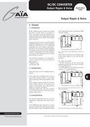
<strong>DC</strong>/<strong>DC</strong> <strong>CONVERTER</strong>Avionics / Military ApplicationApplicationnotesModular Power ArchitectureUp to 50Wfor Avionics/Military ApplicationsStandard28 V<strong>DC</strong>, 24 V<strong>DC</strong>Input BusBusAdaptationStageEMI filterFGDS series(MIL-STD-461, DO-160, ...)Pre-regulatorPGDS series(MIL-STD-704/1275, DO-160, ...)Hold-up andMonitoringStageHold-up moduleHUGD seriesMonitoringsignalsExternalcapacitancePower Stage4W up to 150W4:1 to 10:1Module 1MGDM/I seriesModule 2MGDM/I series Module 3MGDM/I seriesREDEFINING THE SOURCE OF POWER1- General1-1 IntroductionThis application note describes how to use GAIAConverter <strong>DC</strong>/<strong>DC</strong> converters and front-end modulesPGDS-50 and HUGD-50 to built a complete powersupply that meets avionics/military standards.This modular power architecture is dedicated for24V and 28V bus powered electronics up to 50Wpower.1-2 Modular Power ArchitectureThe use of modular power architecture by using«ready-to-use» building block modules offer todesigners a lot of positives.Development time is drastically shorter over atraditionnal custom approach.The use of standard building block modules «massproduced» is cost-effective over a custom design.It is a versatile and multi-applications oriented,qualification is facilitate by using already qualifiedbuilding block.Output voltage Output voltage Output voltage1-3 28V Powered Avionics/MilitaryApplicationsThe 28Vdc input bus is one of the most spreadinput voltage for low power and critical systemsfor :• airborne applications• groundborne applicationsA lot of constrainsts around this input bus areexisting including transients, spikes, recovery inpower fail, electromagnetic interferences,crancking, .....GAIA Converter has developped a standard easyto-useand fully qualified modular power architectureto cover all these requirements.The following sections will underline the differentrequirements to fulfill in the main area such as :• Input voltage requirements,• Electromagnetic interference requirements,• Output noise requirements,• Environmental conditions requirements,• Thermal management.6© Gaia Converter FC05-011.08/06 Revision BFor locations, phone, fax, E-Mail see back cover
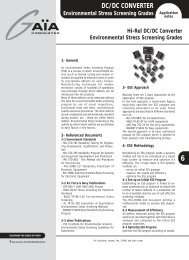
Avionics/Military Modular Power Architecture Up to 50WApplicationnotes2- Input Bus Voltage Requirements2-1 GeneralAirborne or groundborne electronic systems powered directlyfrom 28 V<strong>DC</strong> batteries bus or generator bus, shall sustain wideinput excursions, including transients, spikes, crancking andshut down variations.Those input variations are described in different standards, inwhich the most frequently used are as follows :• For Airborne Applications :• The US MIL-STD-704 standard : “Aircraft Electric PowerCharacteristics”.• The International DO-160 standard : “EnvironmentalConditions and Test Procedures for Airborne Equipment”.• The European En 2282 standard : “Characteristics ofAircraft Electrical Supply”.• The British BSI 3G 100 : “Characteristics of AircraftElectrical Power Supplies”.• The Airbus ADB 100 chap. 8 standard : “EquipementRequirements for Suppliers, electric“• For Groundborne Applications :• The US MIL-STD-1275 standard : “Characteristics of28 V<strong>DC</strong> Electrical Systems in Military Vehicles”.• The British DEF STAN 61-5 Part 6 Electical PowerSupply 28 V<strong>DC</strong> Electrical Systems in Military Vehicles.There are different levels to sustain :• The permanent input voltage range in normal, abnormal andemergency conditions,• The brown-out and transient levels in normal and abnormalconditions,• The spike levels,• The start up voltage and crancking levels,• The shut down (or transparency) levels.The permanent input ranges are achieved by using standard GAIAConverter <strong>DC</strong>/<strong>DC</strong> modules without any additional devices.The brown-out, transient and spikes are more aggressive and areachieved by using GAIA Converter front-end module designated“PGDS-50”. The PGDS-50 module is a transient protection module(see datasheet PGDS-50 for further details)The minimum start up voltage during engine start is also achievedwith the GAIA Converter PGDS series.The shut down level is satisfied by an external hold up device(capacitance and/or a GAÏA Converter hold up module «HUGD-50»as exemple). The HUGD-50 module used in conjunction with anexternal capacitance is a hold-up charger and controller.(see HUGD-50 datasheet for further details)2-2 Modes of OperationsThe typical architecture to cover all the requirements is shown inthe figure herein.This architecture includes :• Front-end modules :• Pre-regulator module PGDS-50• Hold-Up module HUGD-50• a complete range of <strong>DC</strong>/<strong>DC</strong> modulesThe front-end modules cover the following operations dependingon power bus input status :Input Bus Status Active Module OperationsTransients& SpikesPGDS-50Transient & spikesupressorNormal <strong>DC</strong>/<strong>DC</strong> Generation of <strong>DC</strong> voltagesLow lineHold upPGDS-50HUGD-50Boost voltage for proper<strong>DC</strong> operationused in conjunction withcapacitance to provideenergyBusAdaptationStageHold-up andMonitoringStagePower Stage4W up to 150W4:1 to 10:1Module 1MGDM/I seriesEMI filterFGDS series(MIL-STD-461, DO-160, ...)Pre-regulatorPGDS series(MIL-STD-704/1275, DO-160, ...)Hold-up moduleHUGD seriesMonitoringsignalsStandard28 V<strong>DC</strong>, 24 V<strong>DC</strong>Input BusModule 2MGDM/I series Module 3MGDM/I seriesExternalcapacitanceOutput voltage Output voltage Output voltage6© Gaia Converter FC05-011.08/06 Revision BFor locations, phone, fax, E-Mail see back cover2
Avionics/Military Modular Power Architecture Up to 50WApplicationnotes2- Input Bus Voltage Requirements (continued)The following tables describe for airborne and groundborne applications the GAIA Converter modular power architecturecompliance.2-2 For Airborne ApplicationsStandards and Front-end ModulesComplianceNormal Abnormal Emergency LowNormalMIL-STD-704A (cat. A) 25 - 28,5V 23,5 - 30V 17 - 24VMIL-STD-704D/E 22 - 29V 20 - 31,5V 16 - 29VDO-160B/C (cat. A) spike cat. A 22 - 29,5V 20,5 - 32,2V 18VDO-160D (cat. Z) spike cat.A 22 - 30,3V 20,5 - 32,2V 18VAIR2021E 24 - 29V 20,5 - 32,2V 17V10V/50msHighAbnormal80V/50ms18V/15 ms 50V/45ms10V/15s10V/30s12V/50ms46,3V/100ms80V/100ms60V/100msInterruptionAbnormal0V/0,05 to 7s0V/up to 7s0V/ up to 7s0V/up to 7s0V/ up to 5s+/-600V/20µs/+/-600V/10µs/50 W+/-600V/2µs/50 W600V/50µs/50 WGAIA <strong>DC</strong>/<strong>DC</strong> range : 16 - 40V or 16-80VPGDS series : 10V/15s & 80V/100msHUGD series : with capacitorPGDS series : 600V/20µsGAIA <strong>DC</strong>/<strong>DC</strong> range : 16 - 40V or 16-80VPGDS series : 10V/15s & 80V/100msHUGD series : with capacitorGAIA <strong>DC</strong>/<strong>DC</strong> range : 16 - 40V or 16-80VPGDS series : 10V/15s & 80V/100msHUGD series : with capacitorPGDS series : 600V/20µsGAIA <strong>DC</strong>/<strong>DC</strong> range : 16 - 40V or 16-80VPGDS series : 10V/15s & 80V/100msHUGD series : with capacitorPGDS series : 600V/20µsGAIA <strong>DC</strong>/<strong>DC</strong> range : 16 - 40V or 16-80VPGDS series : 10V/15s & 80V/100msHUGD series : with capacitorPGDS series : 600V/20µs2-2 For Groundborne ApplicationsStandardsSteadyStateStartEngineCranking Low HighSpikesGAIA Converter <strong>DC</strong>/<strong>DC</strong> and Front-end ModuleComplianceMIL-STD-1275B (generator + battery)MIL-STD-1275B (battery only)25 - 30V20 - 27V6V/1s6V/1s16V/30s 18V/100ms 40V/50ms16V/30s10V/500ms100V/50ms+/-250V/50µs/15mJ+/-250V/50µs/15mJGAIA <strong>DC</strong>/<strong>DC</strong> range : 9 - 36V transient 40V/100ms or 9 - 45VPGDS series : 6V/1sPGDS series : 600V/20µsGAIA <strong>DC</strong>/<strong>DC</strong> range : 9 - 36V or 9 - 45VPGDS series : 6V/1s & 100V/50msPGDS series : 600V/20µs6MIL-STD-1275B (generator only)23 - 33V/ /10V/500ms100V/50ms+/-250V/50µs/15mJGAIA <strong>DC</strong>/<strong>DC</strong> range : 9 - 36V or 9 - 45VPGDS series : 100V/50msPGDS series : 600V/20µsMIL-STD-1275D (generator +battery)25 - 30V6V/1s16V/30s 18V/500ms 40V/50ms+/-250V/70µs/15mJGAIA <strong>DC</strong>/<strong>DC</strong> range : 9 - 36V transient 40V/100ms or 9 - 45VPGDS series : 6V/1sPGDS series : 600V/20µsMIL-STD-1275D (generator only)23 - 33V/ /15V/500ms100V/50ms+/-250V/50µs/15mJGAIA <strong>DC</strong>/<strong>DC</strong> range : 9 - 36V or 9 - 45VPGDS series : 100V/50msPGDS series : 600V/20µsDEF STAN 61-5 (generator + battery)25 - 30V6V/1s>15V 20V/500ms 40V/50ms+130V/-100V/10V 20V/500ms 40V/50ms+130V/-100V/
Avionics/Military Modular Power Architecture Up to 50WApplicationnotes2- Input Bus Voltage Requirements (continued)2-4 Input Bus Shut-Down RequirementsWhen input bus voltage shut-down the use of a storageenergy device is necessary.There are 2 ways to compy :- the use of a stand(alone bulk capacitor- the use of GAIA Converter HUGD-50 module togetherwxith a capacitor.Both solutions are described thereafter.2-4-1 Bulk Capacitor SolutionDuring bus power drop-out, avionics and military systemsrequire a maintain of operation for saving data andcontrolling the shut-down. The duration of this shut-downoperation is defined in different standards explained inprevious table in section 2-2 and can go up to 7 secondes.To maintain operation during this power drop-out, thetraditional approach is the use of a bulk capacitor connectedat the input of the converters to power them when powerdrops-out. The capacitor needed depends on the systemspecifications, the load and the efficiency of the <strong>DC</strong>/<strong>DC</strong>converters and the amount of capacitor for a given holduptime is determined by the following formula :C1 =( 2 x P x Dt ){ h x ( V1 2 - V2 2 )}where :C : is the required capacitor (in farads)P : is the power at the load (output of converter)(in watts)h : is the efficiency of the converter at rated loadDt : is the required hold up time (in seconds)V1 : is the initial charged capacitor voltage (in volts)V2 : is the low line voltage of <strong>DC</strong>/<strong>DC</strong> converterFor a typical hold-up time of 50 ms with 50W power(at the input of the <strong>DC</strong>/<strong>DC</strong> converter with 80% efficiency)plugged on a MIL-STD-704D 28V bus that can range downto 22V and considering the minimum permanent inputvoltage of GAIA Converter module at 16V, the requiredcapacitance is a huge 18.000 µF/40V rated.2-4-2 Hold Up Module SolutionTo reduce drastically the size of this capacitor, GAIAConverter proposes a hold up module that will charge thecapacitor at a much higher voltage (typically 38V).Moroever this module allows a selection of the minimumthreshold voltage at which the capacitance will begin topower the converters. In this case the amount ofcapacitance for a given hold up time is determined by thefollowing formula :C2 =2 x P x (Dt + 0.01){ h x ( 38 2 - V2 2 )}where :C : is the required capacitor (in farads)P : is the power to the load (output of converter) (in watts)h : is the efficiency of the converter at rated loadDt : is the required hold up time (in seconds)V2 : is the low line voltage of <strong>DC</strong>/<strong>DC</strong> converter (in volts).For a typical hold-up time of 50 ms with 50W power (atthe input of the <strong>DC</strong>/<strong>DC</strong> converter with 80% efficiency)plugged on a MIL-STD-704D 28V bus and using the hold upmodule the capacitance required will decrease down to5.000 µF/40V rated.Moroever this module provides monitoring signals ofcapacitor charge, discharge, power fail, and is able todrive complex avionics systems micro- shut-down, coldand hot start, ......6© Gaia Converter FC05-011.08/06 Revision BFor locations, phone, fax, E-Mail see back cover4
Avionics/Military Modular Power Architecture Up to 50WApplicationnotes2- Input Bus Voltage Requirements (continued)2-5 Typical SchematicsTo take into account the different constraints described intable of section 2-2, GAIA Converter recommends thefollowing schematics integrating either the pre-regulatormodule PGDS-50 for transient, spike and low line operationtogether with the hold-up module HUGD-50 and a bulkcapacitance for drop-out operation.A typical schematic will be built with the following settings :• For HUGD-50- Setting of the «power fail threshold» Vth (adjustablebetween about 9V and 16V) which will determine thevoltage limit underwhich the system will work in holdupmode using only the capacitance energy. This settingis realized with a resistance Rth connected between thepin Vth and the G0 pin :- Rth : Vth unconnected will give a threshold of about16V,- Rth : Vth connected to ground will give a thresholdof about 9 V.If the PGDS-50 is used in conjunction with HUGD-50module the pin Vth has to remain unconnected.- Setting of the «charging current level» between 100mA up to 2A will determine the charging time. Aresistance Rcl connected between the pin Vcl and thepin G0 of 1K will give a charging time of 150µs/µF; a 2Kwill give about 475µs/µF.Additionnal details on these settings are given in the HUGD-50 datasheet together with detailed operations.R*• For PGDS-50No settings are necessary, the PGDS-50 modules need justa voltage reference Vimes connected at a filtered input ofthe power bus.Additionnal details on PGDS-50 is given in the PGDStechnical datasheet.- For bulk capacitanceThe calculation is given by the following formula :2 x P x (Dt+0.01 )C ={ h x ( 38 2 - V2 2 )}where :C : is the required capacitor (in farads)P : is the power to the load (output of converter) (in watts)h : is the efficiency of the converterDt : is the required hold up time (in seconds)V2 : is the low line voltage of <strong>DC</strong>/<strong>DC</strong> converter• Transition capacitorTo help transitionning the system in the different operatingmode, GAIA Converter recommends the use of a transitioncapacitor. A 100µF electrolytic capacitor isrecommended for 50W load and canbe reduced for lower loads. Details are given in HUGDdatasheet.• EMI filterTo sustain EMI requirements a front filter is recommended.The following section 3 describes this filter.VIPower fail signalCapacitor charged signalCapacitor discharged signal+Vo6+ InputVIVoC*1VI2Vimes+Vo61PFVICCCD+Vo6MGDM-seriesGIGoEMI input FilterPGDS50Vc 7HUGD50VI+Vo- InputGIGo4GIOn/Off3Go54GIVth25GoVcl3MGDM-seriesGIGoRth**RclVI+VoOn/OffMGDM-seriesGIGoNote * : Due to possible oscillations caused by surges or fast transients at the input voltage level, it is recommended to implement a RC filter on the VIMES signal; severalimplementations as shown in the above figure can be tested to optimize the design. Typical values for the resistor R is 470 Ohm and for for the capacitance C is 1µF.Note ** : When used in conjunction with PGDS-50 series, the resistance Rth of HUGD module has to be left unconnected.© Gaia Converter FC05-011.08/06 Revision BFor locations, phone, fax, E-Mail see back cover5
Avionics/Military Modular Power Architecture Up to 50WApplicationnotes3- Electromagnetic Interference Compatibility RequirementAirborne or groundborne electronic systems shall alsosustain severe level of electromagnetic interferencerequirements.Those interference levels are defined in different standardswhereas the most popular are :• The US MIL-STD-461C standard : “ElectromagneticInterferance Characteristics, Requirements for Equipment”.• The US MIL-STD-461D/E standards : «Requirements forthe control of electromagnetic Interference Emissions andSusceptibility».• The DO-160D standard : ”Environmental Conditions andTest Procedures for Airborne Equipment”.The requirements are divided into :- Conducted emission (CE),- Conducted susceptibility (CS),- Radiated emission (RE),- Radiated susceptibility (RS).The following tables resume GAIA Converter productscompliance with the requirementsSpecifications MIL-STD-461C MIL-STD-461E DO 160D GAIA Converter module complianceConducted emission (CE) :Low frequencyHigh frequencyCE 01CE 03CE 101CE 102Section 21Section 21module compliant stand alonemodule compliant with additional filterConducted susceptibility (CS) :Low frequencyHigh frequencyCS 01CS 02CS 101CS 114Section 20Section 20module compliant with additional filtermodule compliant with additional filterRadiated emission (RE) :Magnetic fieldElectrical fieldRE 01RE 02RE 101RE 102Section 21Section 21module compliant stand alonemodule compliant stand aloneRadiated susceptibility (RS) :Magnetic fieldElectrical fieldRS 01RS 03RS 101RS 103Section 20Section 20module compliant stand alonemodule compliant stand alone3-1 Compliance with MIL-STD-461C/D/E StandardsTo meet the latests US military standards MIL-STD-461C, MIL-STD-461D and MIL-STD-461E requirements and in particular CE03and CE102 requirements, Gaïa Converter can propose a ready-to-use EMI filter module. Please consult EMI filter datasheet forfurther details.6VIVoVIVoEMI input FilterMGDM-seriesGIGoGIGoCc© Gaia Converter FC05-011.08/06 Revision BFor locations, phone, fax, E-Mail see back cover6
Avionics/Military Modular Power Architecture Up to 50WApplicationnotes4- Lay-out RecommendationGood printed circuit board layout design is essential to achieve proper EMI performance. The two key areas to considerwhile laying-out a board are :- Grounding design,- Component and trace routing.4-1 Grounding designGAIA Converter recommend to use four layer boards. Thetwo outer layers will be used for power and ground planes,and the two inner layers for low levels signals. Wherenecessary, extra planes to beef-up high current paths canbe added on the inner layers.We recommend that the top layer, located closest to themodules, be used for the ground planes and divided intotwo parts as follow :- primary ground part, divided into two sub-parts(see EMI filter design note for further information)- secondary ground parts,Both parts must be as large as possible and spread outover the entire surface of the board; a grid could be usedto avoid a complete copper surface.GAIA Converter recommend the use of a decouplingcommon mode noise capacitance (10nF) between primaryand secondary ground planes. If more than one module isused, additionnal common mode noise capacitance arerecommended.The «case» pin of the modules (if available) can beconnected either to primary or secondary ground planeand a 6 sides shielding can be achieved with the PCBground plane.4-2 Component and trace routing designThe component placement is also a key factor between agood result and a nightmare.The first step in placing the component is to determinethe power flow through the board. The most popular flowstructure is from one side of the board to the other andavoiding cross-overs.If more than one <strong>DC</strong>/<strong>DC</strong> modules is used it is recommendedto place the modules side-by-side so that the power signalscan be easily routed avoiding croos-overs. It is alsorecommended to leave 1/2 inch between each module toavoid that radiation from power stage of one module canaffect the control stage of the adjacent module and causecross-talk.The second step is to place the EMI filter next and asclose as possible to the modules minimizing trace lenghtsto avoid «antenna» phenomenum and minimize loop areasand straight inductances that can limit the effectivenessof the filter. When placing theses components make sureto leave enough room for power carrying traces to runthrough. Please consult also EMI filter design note foradditionnal routing information.GroundSecondary Ground Plane28VVinVout6InputBusEMIFilterPGDS-50Gin GoutVinVout0VPrimary Ground PlaneGroundPrimary Ground PlaneGinGoutCommonmode noisecapacitancePlatedhole© Gaia Converter FC05-011.08/06 Revision BFor locations, phone, fax, E-Mail see back cover7
Avionics/Military Modular Power Architecture Up to 50WApplicationnotes5- Output noiseOutput noise measurements are difficult to make even under the best conditions. A GAIA Converter dedicated applicationnote “Output ripple and noise” is available for complete information.5-1 Output Noise with GAIA Converter Module Stand AloneGaia Converter <strong>DC</strong>/<strong>DC</strong> modules the have following maximum output noises.Type of outputOutput noise3,3 and 5V output 40mVpp up to 20MHz Bandwidth12V output50mVpp up to 20MHz Bandwidth15V output5-2 Output Noise with Additionnal External Filter60mVpp up to 20MHz BandwidthIf the performance is not enough, GAIA Converter has qualified for each <strong>DC</strong>/<strong>DC</strong> converter a simple output LC and commonmode filter as follow :ViVoLGiMGDM SeriesGoC*Common mode noise capacitance C = 10nF cOutput current Less than 1A 1A to 2A 2A to 9AInductance LSuch filter will reduce noises down to :4,7µH, DO1608CCoilcraft1µH, DO1608Coilcraft1µH, DO3316CoilcraftOutput voltage 0 to 5V 12V 15V 24VCapacitance CNumber of cpacitance47µF/10Vtantalum293D Series1 capacitor for each step of2AType of output22µF/20Vtantalum293D Series1 capacitor for each stepof 1A10µF/35Vtantalum293D Series1 capacitor for eachstep of 0.7AOutput noise with external filter10µF/35Vtantalum293D Series1 capacitor for each step of0.7A63,3 and 5V output < 10mVpp up to 20 MHz Bandwidth12V output15V output< 10mVpp up to 20 MHz Bandwidth< 10mVpp up to 20 MHz Bandwidth© Gaia Converter FC05-011.08/06 Revision BMGDB-04J-C with external filterFor locations, phone, fax, E-Mail see back coverMGDB-10-J-C with external filter8
Avionics/Military Modular Power Architecture Up to 50WApplicationnotes6- Compliance with Environmental Condition RequirementsAvionics and military electronic systems shall sustain a highlevel of environmental conditions depending on their use/location.The levels are defined in different standards, among whichthe most frequently used are :• The RTCA/DO-160C standard : “Environmental Conditionsand test Procedures for Airborne Equipment”.• The US MIL-STD-810 standard : “Environmental TestMethod”.• The US MIL-STD-202 standard : “Environmental TestMethod”.• The US MIL-STD-883 standard : “Screening Procedures”.• The French GAM-EG 13B standard : “Essais de comptabilitéà l’environnement climatique, mécanique”• The UK BS3G100 standard : “Environmental ConditionsTest Method”.To verify the suitability of GAIA Converter modules, acomplete qualification test program has been undertakingby an independent laboratory part of the French DefenseAgency CELAR which includes :Test parameterStandardsGAIA Converter<strong>DC</strong>/<strong>DC</strong> module qualificationLife at high temperatureper MIL-STD-202GMethod 108AOperation : 1.000 hrs @ +105°C caseStorage : 1.000 hrs @ +125°C ambientLow temperatureper MIL-STD-810EMethod 502.3Storage : 1.000 hrs @ -55°C ambientTemperature cyclingper MIL-STD-202AMethod 102ANumber of cycles : 200Temperature change : -40°C / +85°CTransfert time : 40 min.Steady state time : 20 minTemperature shockper MIL-STD-202GMethod 107GNumber of shocks : 50Temperature change : -55°C / +105°CTransfert time : < 10 secSteady state time : 30 minLow Pressure (Altitude)per MIL-STD-810EMethod 500.340.000ft, unit functioning1.000ft/min to 70.000ft,unit functioning6Humidity (Cyclic)per MIL-STD-810EMethod 507.3Damp heat : 60% to 88% relative humidityCycle I : (31°C to 41°C) : 240HrsHumidity (Steady state)per MIL-STD-202GMethod 103BDamp heat : 93¨% relative humidityTemperature : 40°CDuration : 56 daysSalt sprayper MIL-STD-810EMethod 509.3Temperature : 35°CDuration : 48 hrsVibrationFrequency rangeAccelerationper MIL-STD-810DMethod 514.310 cycles in each axisfrequency : 10 to 60Hz/60 to 2 KHzacceleration : 0.7mm/10gShock (Half sinus)Peak accelerationDurationper MIL-STD-810DMethod 516.33 shocks in each axisPeak acceleration : 100gduration : 6msBumpsper MIL-STD-810DMethod 516.32000 bumps in each directionduration : 6mspeak acceleration : 40g© Gaia Converter FC05-011.08/06 Revision BFor locations, phone, fax, E-Mail see back cover9
Avionics/Military Modular Power Architecture Up to 50WApplicationnotes7- Thermal ManagementGAIA Converter modules are given for a maximum casetemperature of 105°C. This case temperature correspondsto an internal component temperature far below (designderating) their maximum junction temperature.Usually for designer, environment is explained with ambienttemperature. To rapidly check if this ambient condition iscompliant with the maximum case temperature, the firststep is to find the power dissipated in the converter, thisvalue is calculated as follow :P dissipation= P out/efficiency - P out(Efficiency is given for each module in the technicaldatasheet )GAIA Converter provides for each Hi-Rel converter the thermalresistance Rth case ambient by watt dissipated so themaximum ambient temperature is given with the formula :Tambient = 105°C - Pdiss * RthWhere Tambient is given in °CAn example is given with a MGDM-10 module, 10Wconverter, 86% efficiency used with 10W power and having12°C/W of Rth in worst condition (still air) will be able tobe used at :Tambient= 105 - ( 10 / 86% - 10 ) x 12 = 85°CIf calculated ambient temperature is not compliant withthe requirement an additional thermal path should be foundto lower the thermal resistance with :- Heat sink- Forced air cooling- Larger area of circuit board metallization.A method of removing heat recommended by GAIAConverter is conductive heat sink through direct contactwith the module case.An example is given in the following application whereheat sink is provided by the top case in conductive metal.6© Gaia Converter FC05-011.08/06 Revision BFor locations, phone, fax, E-Mail see back cover10
For more detailed specifications and applications information, contact :International HeadquartersGAÏA Converter - FranceZI de la Morandière33185 LE HAILLAN - FRANCETel. : + (33)-5-57-92-12-80Fax : + (33)-5-57-92-12-89Represented by :North American HeadquartersGAÏA Converter Canada, Inc4038 Le Corbusier BlvdLAVAL, QUEBEC - CANADA H7L 5R2Tel. : (514)-333-3169Fax : (514)-333-4519Information given in this datasheet is believed to be accurate and reliable. However, no responsibility is assumed for the consequence of its use nor for any infringement of patents or other rights of third parties which may result from its use.These products are sold only according to GAIA Converter general conditions of sale, unless otherwise confirmed by writing. Specifications subject to change without notice.Printed in France by GAIA Converter Gaia Converter FC05-011.08/06 Revision B. Graphisme : Philippe Clicq