Experiment 4: The Fabry-Perot Interferometer
Experiment 4: The Fabry-Perot Interferometer
Experiment 4: The Fabry-Perot Interferometer

You also want an ePaper? Increase the reach of your titles
YUMPU automatically turns print PDFs into web optimized ePapers that Google loves.
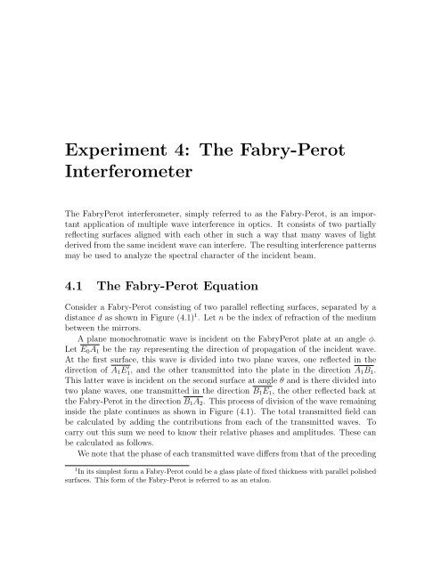
<strong>Experiment</strong> 4: <strong>The</strong> <strong>Fabry</strong>-<strong>Perot</strong><strong>Interferometer</strong><strong>The</strong> <strong>Fabry</strong><strong>Perot</strong> interferometer, simply referred to as the <strong>Fabry</strong>-<strong>Perot</strong>, is an importantapplication of multiple wave interference in optics. It consists of two partiallyreflecting surfaces aligned with each other in such a way that many waves of lightderived from the same incident wave can interfere. <strong>The</strong> resulting interference patternsmay be used to analyze the spectral character of the incident beam.4.1 <strong>The</strong> <strong>Fabry</strong>-<strong>Perot</strong> EquationConsider a <strong>Fabry</strong>-<strong>Perot</strong> consisting of two parallel reflecting surfaces, separated by adistance d as shown in Figure (4.1) 1 . Let n be the index of refraction of the mediumbetween the mirrors.A plane monochromatic wave is incident on the <strong>Fabry</strong><strong>Perot</strong> plate at an angle φ.Let E 0 A 1 be the ray representing the direction of propagation of the incident wave.At the first surface, this wave is divided into two plane waves, one reflected in thedirection of A 1 E ′ 1, and the other transmitted into the plate in the direction A 1 B 1 .This latter wave is incident on the second surface at angle θ and is there divided intotwo plane waves, one transmitted in the direction B 1 E 1 , the other reflected back atthe <strong>Fabry</strong>-<strong>Perot</strong> in the direction B 1 A 2 . This process of division of the wave remaininginside the plate continues as shown in Figure (4.1). <strong>The</strong> total transmitted field canbe calculated by adding the contributions from each of the transmitted waves. Tocarry out this sum we need to know their relative phases and amplitudes. <strong>The</strong>se canbe calculated as follows.We note that the phase of each transmitted wave differs from that of the preceding1 In its simplest form a <strong>Fabry</strong>-<strong>Perot</strong> could be a glass plate of fixed thickness with parallel polishedsurfaces. This form of the <strong>Fabry</strong>-<strong>Perot</strong> is referred to as an etalon.
<strong>Fabry</strong>-<strong>Perot</strong> <strong>Interferometer</strong> 3<strong>The</strong>n the ratios of reflected-to-incident and transmitted-to-incident electric field amplitudesat each interface are 2E ref= − √ R ,E inc(4.4)E trans= √ 1 − R .E inc(4.5)We are now ready to calculate the transmission of the <strong>Fabry</strong>-<strong>Perot</strong>. We will writedown all the fields at the same instant of time t.<strong>The</strong> field of a plane wave is of the formE(t) = E 0 e −iωt+ikz (4.6)where k = 2πn/λ and z is the distance of propagation. Let us set z = 0 at point A 1 ,at the input face so that the incident wave can be written asE inc = E 0 e −iωt . (4.7)<strong>The</strong> transmitted field amplitude across the first surface, according to Eq.(4.5),is √ 1 − R E 0 and after crossing the second surface, it is √ 1 − R · √1− RE 0 =(1 − R) E 0 . <strong>The</strong> transmitted field E 1 at B 1 is thenE 1 = (1 − R)E 0 e −i(ωt−k A 1B 1 ) . (4.8)where the distance A 1 B 1 = d/ cos φ. Writing the constant phase k A 1 B 1 = kd/ cos φ =δ 0 we can write E 1 asE 1 = (1 − R)E 0 e −i(ωt−δ 0) . (4.9)To write down E 2 we note that the wave transmitted across the first surface isreflected twice inside the plate before being transmitted. Its amplitude will thusgather amplitude factors √ 1 − R ( √ R) ( √ R) √ 1 − R = (1 − R)R and an additionalphase factor e i2δ relative to E 1 ,E 2 = (1 − R)RE 0 e −i(ωt−δ 0) e i2δ (4.10)2 <strong>The</strong> minus sign takes into account the phase change at reflection from a denser medium.
4 <strong>Fabry</strong>-<strong>Perot</strong> <strong>Interferometer</strong>Similar considerations for other waves lead to the following expressions for the transmittedwavesE 1 = E 0 (1 − R)e −i(ωt−δ 0)E 2 = E 0 (1 − R)Re −i(ωt−δ 0) e i2δE 3 = E 0 (1 − R)R 2 e −i(ωt−δ 0) e i4δ(4.11)E 4 = E 0 (1 − R)R 3 e −i(ωt−δ0) e i6δ· · ·E N = E 0 (1 − R)R N−1 e −i(ωt−δ0) e i(N−1)2δIf the incident wave and the plates are wide enough and reflectivity is high therewill be a large number of contributions. For all practical purposes we can take thenumber of transmitted waves to be infinitely large. <strong>The</strong> total transmitted field is thenobtained by summing the infinite geometric series 3E T = E 1 + E 2 + E 3 + · · ·= E 0 (1 − R)e −i(ωt−δ 0) ( 1 + Re i2δ + R 2 e i4δ + · · · )= E 0(1 − R)e −i(ωt−δ 0)1 − Re i2δ . (4.12)Since the (time averaged) intensity is proportional to the modulus squared of thefield amplitude, the transmitted intensity I T is given in terms of the incident waveintensity I 0 asI T ==I 0 (1 − R) 21 + R 2 − 2R cos 2δ = I 0 (1 − R) 21 + R 2 − 2R + 2R(1 − cos 2δ)I 0 (1 − R) 2(1 − R) 2 + 4R sin 2 δ(4.13)(4.14)This can be written in the formwhere F is the coefficient of finesseI T =F =I 01 + F sin 2 δ , (4.15)4R(1 − R) 2 , (4.16)3 An infinite geometric series 1 + x + x 2 + x 3 + · · · with x < 1 has the sum 1/(1 − x).
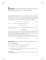
<strong>Fabry</strong>-<strong>Perot</strong> <strong>Interferometer</strong> 5and the phase δ from Eq. (4.2) is given byδ =2πnd cos θλ. (4.17)From Eq. (4.15) we see that the transmitted intensity is a periodic function of δ thatvaries between a maximum and a minimum as δ changes[I T ] max = I 0 , δ = pπ , p an integer (4.18)[I T ] min = I 0(p1 + F , δ = + 1 )π (4.19)2I TI o1 2 I oR= 0.10.50pπ0.9(p+1)πδFigure 4.2: <strong>Fabry</strong>-<strong>Perot</strong> transmission as a function of δ.Figure (4.2) shows the transmitted intensity I Tas a function of δ. Note that thepeaks get narrower as the mirror reflectivity (and therefore the coefficient of finesseF ) increases. When peaks are very narrow, light can be transmitted only if the plateseparation d, refractive index n, and the wavelength λ satisfy the precise relationδ =2πnd cos θλ= integer × π ≡ pπ , (4.20)otherwise no light is transmitted. It is this property that permits the <strong>Fabry</strong>-<strong>Perot</strong> toact as very narrow band-pass filter for fixed d.
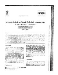
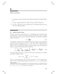
6 <strong>Fabry</strong>-<strong>Perot</strong> <strong>Interferometer</strong>If the incident light contains many wavelengths of varying intensities, we cananalyze its spectrum (wavelength/frequency and intensity) by scanning the length dof the <strong>Fabry</strong>-<strong>Perot</strong> because for a given separation d, the <strong>Fabry</strong>-<strong>Perot</strong> transmits onlythe wavelength that satisfies Eq. (4.20). In this mode the <strong>Fabry</strong>-<strong>Perot</strong> is referred toas a spectrum analyzer. Also note that as we scan the <strong>Fabry</strong>-<strong>Perot</strong> the transmissionpattern will repeat when δ increases by π.Integer p in Eq. (4.20) is referred to as the order of the transmission peak (or thefringe). Note that p has its maximum value for θ = 0. If the width of the pump beamwas very large, and all the rays of light were incident at the same angle, we wouldnot receive any light at angles other than those satisfying Eq. (4.20). In practice,the incident light often has some divergence so that the relation (4.20) is satisfied forother angles as well [see Figure (4.3)]. Consequently, in transmitted light we will seeconcentric rings corresponding to rays entering the <strong>Fabry</strong><strong>Perot</strong> at angles θ 1 and θ 2 , ifEq. (4.20) is satisfied.θ 1θ 2Side view Front viewFigure 4.3: <strong>The</strong> output of a <strong>Fabry</strong>-<strong>Perot</strong> illuminated by a diverging set of rays consistsof concentric rings.4.2 <strong>Fabry</strong><strong>Perot</strong> Finesse<strong>The</strong> peaks in Figure (4.2) are not infinitely sharp because the surfaces cannot be madeperfectly reflecting. This limits the instrument’s (spectral) resolution [Its ability totell two closely spaced wavelengths or frequencies apart]. A number F called “finesse”describes the resolution of the instrument. Its significance is shown in Figure (4.4).Note that successive transmission maxima are separated by ∆δ = π and the peakwidth δ c is defined be the full width at half maximum (FWHM). <strong>The</strong> finesse for
<strong>Fabry</strong>-<strong>Perot</strong> <strong>Interferometer</strong> 7the instrument is defined as the maximum number of resolvable peaks that can beinserted in the interval π,F = π δ c(4.21)I TI o1 2 I oδ cπ0pπ(p+1)πδFigure 4.4: Finesse is a measure of the sharpness of transmission peaks.To determine δ c , we look for the values of δ, for which the transmitted intensityis reduced to half of its peak value [See Figure (4.5)]. Near a transmission peak ofintegral order p, the points where the intensity falls to half of its maximum value areat δ = pπ ± 1 2 δ c. At these points we obtain from Eq. (4.15)This equation easily gives12 I 0 =sin( 12 δ cI 01 + F sin 2 ( 1 2 δ c) . (4.22))= 1 √F= 1 − R2 √ R(4.23)In most cases of practical interest, the width of the peak is small compared to thefree spectral range, δ c ≪ π. This is the case when F is large. We can then use theapproximation sin( 1 2 δ c) ≈ 1 2 δ c to obtainδ c = 2 √F=(1 − R)√R. (4.24)
8 <strong>Fabry</strong>-<strong>Perot</strong> <strong>Interferometer</strong>I TI o1 2 I oδ c0pπ−δ c /2 pπ pπ +δ c /2δFigure 4.5: Peak width δ c is defined to be the full width at half maximum.From our definition of finesse (4.20) then we findF = π = π√ Rδ c 1 − R ≡= π√ F2. (4.25)As an example, consider a <strong>Fabry</strong>-<strong>Perot</strong> consisting of two mirrors with R = 0.99separated by an air gap (n = 1) of 2.500000 cm. <strong>The</strong> source of light is a hypotheticallaser emitting light of wavelength 500.0000 nm, incident normally (θ = 0) on themirrors. <strong>The</strong>n from the expression for δ (Eq.(4.17)) we findδ = 10, 000 π (4.26)<strong>The</strong> transmission should be maximum under this condition.What happens if we gradually increase the air gap? To answer this,suppose we begin at a transmission peak at θ = 0. <strong>The</strong>n the wavelength λ of maximumtransmission and <strong>Fabry</strong>-<strong>Perot</strong> separation d satisfy the conditionδ ≡ 2πdλ = pπ ⇒ λ = 2d p(4.27)where p is an integer. As we vary the <strong>Fabry</strong>-<strong>Perot</strong> separation, the wavelength ofmaximum transmission will change. Thus if the <strong>Fabry</strong>-<strong>Perot</strong> separation changes by
<strong>Fabry</strong>-<strong>Perot</strong> <strong>Interferometer</strong> 9an amount ∆d, the wavelength transmitted will be (fixed p)λ + δλ =2(d + δd)p. (4.28)If we continue to increase the separation, then at some point, when the separationhas increased by an amount ∆d, the original wavelength λ will be transmitted againbut this time satisfying the relationλ =2(d + ∆d)p + 1. (4.29)Note that this will be in addition to another wavelength λ + ∆λ satisfyingλ ′ ≡ λ + ∆λ =2(d + ∆d)p. (4.30)Equations (4.29) and (4.30) imply that when the separation can simultaneously fitp + 1 half wavelengths of λ and p half wavelengths of λ + ∆λ both wavelengthswill be transmitted. In this case we would not be able to tell if the <strong>Fabry</strong>-<strong>Perot</strong> istransmitting a new wavelength or the original one. So how much can we scan beforethis confusion or overlap of orders arises? <strong>The</strong> answer from Eqs. (4.30) is∆d = λ 2 . (4.31)Using this result in Eq. (4.30) and substituting value of p from Eq. (4.25) [or (4.29)] 4we obtain the range of wavelengths that can be freely scanned without overlappingof orders is∆λ = λ2(4.32)2dScanning beyond this point will simply repeat the pattern already encountered and isof little interest to us. Wavelength scanning range ∆λ free of any repetition is calledthe free spectral range (FSR) of the <strong>Fabry</strong>-<strong>Perot</strong>. This FSR in terms of scannedwavelength corresponds to the free spectral range in terms of phase, δ F SR = π.Exercise: Compute FSR in terms of frequency ν = c/λ.In our numerical example, the free spectral range turns out to be 0.005 nm, whichtells us that we are capable of looking very closely into the spectrum of the laser in4 It does not matter which equation is used as long as p is large.
10 <strong>Fabry</strong>-<strong>Perot</strong> <strong>Interferometer</strong>I TI o1 2 I oλ 2 /2d λ 2 /2d0λ −Δλλλ +ΔλλFigure 4.6: Transmitted intensity as a function of wavelength λ.the range 500.0000 ± 0.0050 nm. This is particularly helpful in the event that theoutput of the laser actually consists of several closely spaced spectral lines.According to Eq. (4.25), with 97% reflectivity mirrors, a finesse of 100 can obtained.This means that we can ultimately resolve two spectral lines separated byone-hundredth of the Free Spectral Range, or by 0.00005 nm, indeed a small separation.By contrast, the resolution of the best spectrometers available today can onlyreach .01 nm.4.3 Applications<strong>Fabry</strong>-<strong>Perot</strong>s are particularly useful in the field of spectroscopy whenever high resolutionis needed. Other applications include astronomy and intracavity laser-linenarrowing. A traditional grating spectrometer is useful when the needed resolution isof the order of 0.01 nm while the <strong>Fabry</strong>-<strong>Perot</strong> finds application in the 0.1 nm to 10 −6nm range. To go below 10 −6 nm, a third technique called “heterodyne detection” isused. This involves beating an unknown frequency with a reference light wave andmeasuring the beat frequency.
<strong>Fabry</strong>-<strong>Perot</strong> <strong>Interferometer</strong> 11Part 1<strong>The</strong> outcome of this experiment will be a transmission curve I T(δ) displayed on anoscilloscope. To understand the experimental procedure described in Part 2, let usfirst perform some calculations.<strong>The</strong> reflectivity of the mirrors is given by the manufacturer to be 97.5%. Assumingthat your set up is perfect, plot the curve I T/I 0 [See Eq. (4.15)] for thisparticular reflectivity and calculate the finesse of the <strong>Fabry</strong>-<strong>Perot</strong>.You will notice that the plotted peaks are quite sharp, but in the experiment theywill be somewhat broader. This is due to imperfections in the experimental set up.We shall consider a few of these.In the discussion of the theory, we assumed that the detection system was capableof looking at a single point at the output of the <strong>Fabry</strong>-<strong>Perot</strong>. In practice, the detectorlooks at a small area of the output plane and this can profoundly affect our results. Tosee this, let us assume that our experimental set up consists of a laser, a <strong>Fabry</strong>-<strong>Perot</strong>,a pinhole, and a detector as shown in Figure (4.7)dDw<strong>Fabry</strong>-<strong>Perot</strong> output pinhole detectorFigure 4.7: Detector aperture must not look at more than one fringe (transmissionmaximum) at a time. This can be accomplished by placing a pin hole of suitable sizein front of the detector.We shall assume that the laser behaves as a point source. <strong>The</strong> output of the <strong>Fabry</strong>-<strong>Perot</strong> then consists of concentric rings corresponding to the transmission peaks [Fig.(4.3)]. Figure (4.7) shows a side view of the output. <strong>The</strong> distance D is the separation
<strong>Fabry</strong>-<strong>Perot</strong> <strong>Interferometer</strong> 15expected ratio of the laser mode separation to the free spectral range of the<strong>Fabry</strong>-<strong>Perot</strong>? How does this compare with the measured value?