Electromagnetic flow meters - OPTIFLUX 4000 - Forbes Marshall
Electromagnetic flow meters - OPTIFLUX 4000 - Forbes Marshall
Electromagnetic flow meters - OPTIFLUX 4000 - Forbes Marshall

Create successful ePaper yourself
Turn your PDF publications into a flip-book with our unique Google optimized e-Paper software.
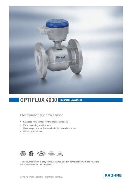
1 PRODUCT FEATURES<strong>OPTIFLUX</strong> <strong>4000</strong>ConstructionThe measuring tube of the sensor has a smooth,cylindrical shape. This design, consisting of acircular cross section (no internal or moving parts)and a homogeneous magnetic field, forms the basisfor a <strong>flow</strong>-optimized pipe cross section, therebyproviding reliable measurements that are largelyindependent of the <strong>flow</strong> profile. This design allowsthe sensor to measure the <strong>flow</strong> bi-directional.As an additional benefit, there is no possibility forproduct to build up and the free cross section sizedto the customer pipeline creates no pressure drop.In addition, the required straight inlet and outletruns are only 5D and 2D. The liner of the measuringtube is made of high tech plastic or hard rubber andis resistant to vacuum, corrosion, aging andabrasion. The surface and shape of the measuringtube also minimize mineral deposits, resulting inexemplary measurement quality - even over the longtermDesign and performance<strong>Electromagnetic</strong> <strong>flow</strong><strong>meters</strong> have many importantadvantages over their mechanical counterparts:outstanding long-term stability, maximum processreliability, no maintenance - to name just a few. As aresult, these <strong>meters</strong> can deliver precise and reliablemeasurements for many years.The <strong>flow</strong>meter has extensive factory-set diagnosticfunctions that provide continuous self diagnosis inaccordance with e.g. NAMUR, OIML, ISO/EN andMID. Converter operation is also monitoredcontinuously, as are the sensor electrodes, the <strong>flow</strong>profile and electronic functions. Malfunctions andirregularities are detected and immediatelydisplayed on the high-contrast, high-resolutiondisplay.6www.krohne.com03/2009 - <strong>4000</strong>525101 - TD <strong>OPTIFLUX</strong> <strong>4000</strong> R04 en
<strong>OPTIFLUX</strong> <strong>4000</strong>PRODUCT FEATURES 11.3 Measuring principleAn electrically conductive fluid <strong>flow</strong>s inside an electrically insulating pipe through a magneticfield. This magnetic field is generated by a current, <strong>flow</strong>ing through a pair of field coils. Inside ofthe fluid, a voltage U is generated:U = v * k * B * Din which:v = mean <strong>flow</strong> velocityk = factor correcting for geometryB = magnetic field strengthD = inner diameter of <strong>flow</strong> meterThe signal voltage U is picked off by electrodes and is proportional to the main <strong>flow</strong> velocity v andthus the <strong>flow</strong> rate q. The signal voltage is quite small (typically 1 mV at v = 3 m/s / 10 ft/s and fieldcoil power of 1 W). Finally, a signal converter is used to amplify the signal voltage, filter it(separate from noise) and convert it into signals for totalising, recording and output processing.1 Voltage (induced voltage proportional to <strong>flow</strong> velocity)2 Electrodes3 Magnetic field4 Field coils03/2009 - <strong>4000</strong>525101 - TD <strong>OPTIFLUX</strong> <strong>4000</strong> R04 enwww.krohne.com7
2 TECHNICAL DATA<strong>OPTIFLUX</strong> <strong>4000</strong>2.1 Technical data• The following data is provided for general applications. If you require data that is morerelevant to your specific application, please contact us or your local representative.• Additional information (certificates, special tools, software,...) and complete productdocumentation can be downloaded free of charge from the website (Downloadcenter).Measuring systemMeasuring principleApplication rangeMeasured valuePrimary measured valueSecondary measured valueFaraday's lawElectrically conductive fluidsFlow velocityVolume <strong>flow</strong>, mass <strong>flow</strong>, electrical conductivity, coil temperatureDesignFeaturesModular constructionCompact versionRemote versionFlange version with full bore <strong>flow</strong> tubeStandard as well as higher pressure ratingsBroad range of nominal sizesIndustry specific insertion lengthsThe measurement system consists of a <strong>flow</strong> sensor and a signalconverter. It is available as compact and as separate version. Moreinformation about the signal converter can be found in thedocumentation of the signal converter.With IFC 100 converter: <strong>OPTIFLUX</strong> 4100 CWith IFC 300 converter: <strong>OPTIFLUX</strong> 4300 CIn wall (W) mount version with IFC 100 converter: <strong>OPTIFLUX</strong> 4100 WIn field (F), wall (W) or rack (R) mount version with IFC 300 converter:<strong>OPTIFLUX</strong> 4300 F, W or RNominal diameter With IFC 100 converter: DN2.5...1200 / 1/10...48"With IFC 300 converter: DN2.5...3000 / 1/10...120"Measurement range-12...12 m/s / -40...40 ft/s8www.krohne.com03/2009 - <strong>4000</strong>525101 - TD <strong>OPTIFLUX</strong> <strong>4000</strong> R04 en
<strong>OPTIFLUX</strong> <strong>4000</strong>TECHNICAL DATA 2Measuring accuracyReference conditionsMaximum measuring errorRepeatabilityLong term stabilitySpecial calibrationOperating conditionsTemperatureProcess temperatureAmbient temperatureStorage temperatureMedium: waterTemperature: 20°C / 68°FInlet section: 10 DNOutlet section: 5 DNFlow velocity: > 1 m/s / > 3 ft/sOperating pressure: 1 bar / 14.5 psigValve closing time variation: < 1 msWet calibrated on EN 17025 accredited calibration rig by directvolume comparisonRelated to volume <strong>flow</strong> (MV = Measured Value)These values are related to the pulse / frequency outputThe additional typical measuring deviation for the current output is±10 μAWith IFC 100 converter:DN2.5...6: ± 0.4% of MV + 1 mm/sDN10...1200: ± 0.3% of MV + 1 mm/sWith IFC 300 converter:DN2.5...6: ± 0.3% of MV + 2 mm/sDN10...1600: ± 0.2% of MV + 1 mm/sDN1800...3000: ± 0.3% of MV + 2 mm/s±0.1% of MV, minimum 1 mm/s±0.1% of MVBetter accuracies optionalTemperature depends on the liner material.PTFE: -40...+180°C / -40...+356°FPFA: -40...+180°C / -40...+356°FETFE: -40...+120°C / -40...+248°FHard rubber: -5...+80°C / 23...+176°FPU: -5...+65°C / 23...+149°FFor Ex versions different temperatures count. Please see therelevant Ex documentation for details.Non-Ex: -40…+65°C / -40…+149°FEx: -40…+60°C / -40…+140°F-50…+70°C / -58…+158°F03/2009 - <strong>4000</strong>525101 - TD <strong>OPTIFLUX</strong> <strong>4000</strong> R04 enwww.krohne.com9
2 TECHNICAL DATA<strong>OPTIFLUX</strong> <strong>4000</strong>PressureAmbientNominal flange pressureDIN (EN 1092-1)ISO insertion lengthASME B16.5JISVacuum loadPressure ranges for secondarycontainmentAtmosphericInformation for sizes larger than DN2000 / ASME80" on request.Standard:PN6 for DN1200...2000PN10 for DN200...1000PN16 for DN65 and DN100...150PN40 for DN2.5...50 and DN80Option:PN10 for DN1200...2000PN16 for DN200...2000PN25 for DN65 and DN100...1000PN40 for DN65 and DN100...600Other pressures on requestOptional for DN15...600Standard:150 lbs RF for ASME1/10...24"Option:300 lbs RF for ASME1/10...24"600 lbs RF for ASME3/8...24"900 lbs RF for ASME3/8...12"1500 lbs RF for ASME3/8...12"Other pressures on requestStandard:10 K for DN50...100020 K for DN2.5...40Option:20 K for DN200...600Other pressures on requestFor information on pressure limits depending on liner material seechapter "Vacuum load".Pressure resistant up to 40 bar / 580 psiBurst pressure up to approx. 160 bar / 2320 psi10www.krohne.com03/2009 - <strong>4000</strong>525101 - TD <strong>OPTIFLUX</strong> <strong>4000</strong> R04 en
<strong>OPTIFLUX</strong> <strong>4000</strong>TECHNICAL DATA 2Chemical propertiesPhysical conditionLiquidsElectrical conductivityWater: ≥ 20 μS/cmNon water: ≥ 1 μS/cmPermissible gas content (volume) ≤ 5%Permissible solid content ≤ 70%(volume)Recommended <strong>flow</strong> velocity -12...12 m/s / -40...40 ft/sOther conditionsProtection category acc. to IEC529 / EN 60529Standard: IP 66/67 (NEMA 4/4X/6)Optional: IP 68 (NEMA 6P)Vibration resistance IEC 68-2-6Random vibration test IEC 68-2-34Shock test IEC 68-2-27Installation condtitionsInlet runOutlet runDimensions and weightsMaterialsSensor housingFlangeLinerGrounding ringsMeasuring electrodesGrounding electrodes (option)≥ 5DN (without disturbing <strong>flow</strong>, after a single 90° bend)≥ 10DN (after a double bend 2x 90°)≥ 10DN (behind a control valve)≥ 2DNFor detailed information see chapter "Dimensions and weights".Standard: sheet steel, PU coatedOption: stainless steelOther materials on request.Standard: carbon steel, PU coatedOption: stainless steelOther materials on requestPTFE: standard for DN20, optional for DN200...600PFA: standard for DN2.5...6 and DN25...150ETFE: standard for DN200...2000PU: optional for DN200...1800hard rubber: optional for DN200...2000 (Ex only)Other materials on request.Stainless steel, Hastelloy ® C, Titanium, TantalumOther materials on requestAlso available as alternative for grounding rings (IFC 300 only):Virtual Reference.Standard: Hastelloy ® COption: Platinum, Stainless steel, Titanium, Tantalum (DN2.5...1200),low noise Hastelloy ® C4 (DN10...2000), Low noise SS 316 Ti (1.4571)(DN10...2000)Other materials on request.Same material as measuring electrodes.03/2009 - <strong>4000</strong>525101 - TD <strong>OPTIFLUX</strong> <strong>4000</strong> R04 enwww.krohne.com11
2 TECHNICAL DATA<strong>OPTIFLUX</strong> <strong>4000</strong>Process connectionsDINASMEJISDesign of gasket surfaceElectrical connectionsSignal cableType AType BApprovals and certificationsCE SignHazardous areasATEXFMCSAIEC-ExNEPSIDN2.5...3000 in PN 2.5...40 (others on request)1/10...120" in 150...2500 lbs RF (others on request)DN2.5...1000 in JIS 10...20 K (others on request)RF (others on request)Only for remote systemsStandard cable, double shielded.Max. length: 600 m / 1950 ft (dep. on electrical conductivity andmeasuring sensor). See documentation of the converter for moreinformation.Optional cable, triple shielded.Max. length: 600 m / 1950 ft (dep. on electrical conductivity andmeasuring sensor). See documentation of the converter for moreinformation.This device fulfills the statutory requirements of the EC directives.The manufacturer certifies successful testing of the product byapplying the CE mark.with IFC 100 converter:KEMA 08 ATEX 0157 XII 2 G Ex e ia mb IIC T4II 2 G Ex d ia mb T4II 2 G Ex e ia mb q T4...T3II 2 D Ex tD A21 IP64 T120°Cwith IFC 300 converter:KEMA 04 ATEX 2125 XII 2 GD EEx me ia IICII 2 GD EEx de ia IICII 2 GD EEx qe ia IICII 2 GD EEx e ia IICT6...T3 or T5...T3For more details, see Ex documentation of sensor and converter.Class I, Div 2, groups A, B, C and DClass II, Div 2, groups F and GClass III, Div 2, groups F and GClass I, Div 2, groups A, B, C and DClass II, Div 2, groups F and GpendingGYJ05234 / GYJ05237Ex me ia IIC T6...T3Ex de ia II T6...T3Ex qe ia IIC T6...T3Ex e ia IIC T6...T312www.krohne.com03/2009 - <strong>4000</strong>525101 - TD <strong>OPTIFLUX</strong> <strong>4000</strong> R04 en
<strong>OPTIFLUX</strong> <strong>4000</strong>TECHNICAL DATA 2Other approvals and standards<strong>Electromagnetic</strong> compatibilityLow Voltage DirectivePressure Equipment DirectiveCustody transferHygieneDirective: 89/336/EEC, NAMUR NE21/04Harmonized standard: EN 61326-1 : 2006Directive: 2006/95/ECHarmonized standard: EN 61010 : 2001Directive: 97/23/ECCategory I, II or SEPFluid group 1Production module HStandard: withoutOption: MI-001, MI-005, OIML R-49, OIML R-117PFA liner is FDA approved.03/2009 - <strong>4000</strong>525101 - TD <strong>OPTIFLUX</strong> <strong>4000</strong> R04 enwww.krohne.com13
2 TECHNICAL DATA<strong>OPTIFLUX</strong> <strong>4000</strong>2.2 Vacuum loadDiameterMax.pressureVacuum load in mbar abs. at a process temperature of[mm] [bar] 40°C 60°C 70°C 80°C 90°C 100°C 120°C 140°C 180°CLiner in PFADN2.5...150 50 0 0 0 0 0 0 0 0 0Liner in HardrubberDN200...300 150 250 400 400 400 - - - - -DN350...3000 150 500 600 600 600 - - - - -Liner in ETFEDN200...2000 150 100 100 100 100 100 100 100 - -Liner in PTFEDN10...20 50 0 0 0 0 0 0 500 750 1000DN200...300 50 500 750 1000 1000 1000 1000 1000 1000 1000DN350...600 50 800 1000 1000 1000 1000 1000 1000 1000 1000Liner in PUDN200...1800 1500 500 600 - - - - - - -DiameterMax.pressureVacuum load in psia at a process temperature of[inches] [psi] 104°F 140°F 158°F 176°F 194°F 212°F 248°F 284°F 356°FLiner in PFA1/10...6" 725 0 0 0 0 0 0 0 0 0Liner in Hardrubber8...12" 2176 3.6 5.8 5.8 5.8 - - - - -14...120" 2176 7.3 8.7 8.7 8.7 - - - - -Liner in ETFE8...72" 2176 1.5 1.5 1.5 1.5 1.5 1.5 1.5 - -Liner in PTFE3/8...3/4" 725 0 0 0 0 0 0 7.3 10.9 14.58...12" 725 7.3 10.9 14.5 14.5 14.5 14.5 14.5 14.5 14.514...24" 725 11.6 14.5 14.5 14.5 14.5 14.5 14.5 14.5 14.5Liner in PU8...72" 21756 7.3 8.7 - - - - - - -14www.krohne.com03/2009 - <strong>4000</strong>525101 - TD <strong>OPTIFLUX</strong> <strong>4000</strong> R04 en
<strong>OPTIFLUX</strong> <strong>4000</strong>TECHNICAL DATA 22.3 Dimensions and weightsRemote version a = 77 mm / 3.1"b = 139 mm / 5.5" 1c = 106 mm / 4.2"Total height = H + aCompact version withIFC 300a = 155 mm / 6.1"b = 230 mm / 9.1" 1c = 260 mm / 10.2"Total height = H + aCompact version withIFC 100 (0°)a = 82 mm / 3.2"b = 161 mm / 6.3" 1c = 257 mm / 10.1"Total height = H + aCompact version withIFC 100 (45°)a = 186 mm / 7.3"b = 161 mm / 6.3"c = 184 mm / 2.7"Total height = H + a1 The value may vary depending on the used cable glands.• All data given in the following tables are based on standard versions of the sensor only.• Especially for smaller nominal sizes of the sensor, the converter can be bigger than thesensor.• Note that for other pressure ratings than mentioned, the dimensions may be different.• For full information on converter dimensions see relevant documentation.03/2009 - <strong>4000</strong>525101 - TD <strong>OPTIFLUX</strong> <strong>4000</strong> R04 enwww.krohne.com15
2 TECHNICAL DATA<strong>OPTIFLUX</strong> <strong>4000</strong>DIN/ISO flangesNominal size Dimensions [mm] Approx.weight [kg]DN PN [bar] L H WDIN2.5 40 130 - 142 90 34 40 130 - 142 90 36 40 130 - 142 90 310 40 130 1 - 106 90 615 40 130 1 200 106 95 620 40 150 200 158 105 725 40 150 200 140 115 532 40 150 200 157 140 640 40 150 200 166 150 750 40 200 200 186 165 1165 16 200 200 200 185 980 40 200 200 209 200 14100 16 250 250 237 220 15125 16 250 250 266 250 19150 16 300 300 300 285 27200 10 350 350 361 340 34250 10 400 450 408 395 48300 10 500 500 458 445 58350 10 500 550 510 505 78400 10 600 600 568 565 101450 10 600 - 618 615 111500 10 600 - 671 670 130600 10 600 - 781 780 165700 10 700 - 898 895 248800 10 800 - 1012 1015 331900 10 900 - 1114 1115 4301000 10 1000 - 1225 1230 5071200 6 1200 - 1417 1405 5551400 6 1400 - 1619 1630 7651600 6 1600 - 1819 1830 10351800 6 1800 - 2027 2045 14702000 6 2000 - 2259 2265 18601 150 mm for construction according to order code VN03.ISO16www.krohne.com03/2009 - <strong>4000</strong>525101 - TD <strong>OPTIFLUX</strong> <strong>4000</strong> R04 en
<strong>OPTIFLUX</strong> <strong>4000</strong>TECHNICAL DATA 2150 lbs flangesNominal size Dimensions [inches] Approx. weight[lbs]ASME PN [psi] L H W1/10" 284 5.12 5.59 3.50 61/8" 284 5.12 5.59 3.50 6¼" 284 5.12 5.59 3.50 63/8" 284 5.12 1 5.08 3.50 12½" 284 5.12 1 5.08 3.50 12¾" 284 5.91 5.28 3.88 181" 284 5.91 5.39 4.25 181 ½" 284 5.91 6.10 5.00 222" 284 7.87 7.05 5.98 293" 284 7.87 8.03 7.50 374" 284 9.84 9.49 9.00 515" 284 9.84 10.55 10.0 606" 284 11.81 11.69 11.0 758" 284 13.78 14.25 13.5 9510" 284 15.75 16.3 16.0 14312" 284 19.69 18.78 19.0 20714" 284 27.56 20.67 21.0 28416" 284 31.50 22.95 23.5 36418" 284 31.50 24.72 25.0 41020" 284 31.50 26.97 27.5 49224" 284 31.50 31.38 32.0 6751 5.91" for construction according to order code VN03• Pressures are applicable at 20°C / 68°F.• For higher temperatures, the pressure and temperature ratings are as per ASME B16.5 (up to24") or ASME B16.47 (>24").• Dimensions for other sizes on request.03/2009 - <strong>4000</strong>525101 - TD <strong>OPTIFLUX</strong> <strong>4000</strong> R04 enwww.krohne.com17
2 TECHNICAL DATA<strong>OPTIFLUX</strong> <strong>4000</strong>300 lbs flangesNominal size Dimensions [inches] Approx. weight[lbs]ASME PN [psi] L H W1/10" 741 5.12 5.59 3.75 61/8" 741 5.12 5.59 3.75 6¼" 741 5.12 5.59 3.75 63/8" 741 5.12 1 5.24 3.75 15½" 741 5.12 1 5.24 3.75 15¾" 741 5.91 5.67 4.62 201" 741 5.91 5.71 4.87 181½" 741 7.87 6.65 6.13 202" 741 9.84 7.32 6.50 293" 741 9.84 8.43 8.25 374" 741 11.81 10.00 10.0 516" 741 12.60 12.44 12.5 798" 741 15.75 15.04 15.0 15710" 741 19.69 17.05 17.5 24712" 741 23.62 20.00 20.5 37514" 741 27.56 21.65 23.0 47416" 741 31.50 23.98 25.5 63920" 741 31.50 28.46 30.5 93724" 741 31.50 33.39 36.0 13451 5.91" for construction according to order code VN03• Pressures are applicable at 20°C / 68°F.• For higher temperatures, the pressure and temperature ratings are as per ASME B16.5 (up to24") or ASME B16.47 (>24").• Dimensions for other sizes on request.18www.krohne.com03/2009 - <strong>4000</strong>525101 - TD <strong>OPTIFLUX</strong> <strong>4000</strong> R04 en
<strong>OPTIFLUX</strong> <strong>4000</strong>INSTALLATION 33.1 Intended useThe measurement of volumetric <strong>flow</strong>rate of electrically conductive fluids. Basic measurement isthe <strong>flow</strong> velocity upon which all other measurements are based.3.2 Installation conditions3.2.1 Inlet and outletFigure 3-1: Recommended inlet and outlet1 ≥ 5DN2 ≥ 2DN3.2.2 Mounting positionFigure 3-2: Mounting position03/2009 - <strong>4000</strong>525101 - TD <strong>OPTIFLUX</strong> <strong>4000</strong> R04 enwww.krohne.com19
3 INSTALLATION<strong>OPTIFLUX</strong> <strong>4000</strong>3.2.3 Flange deviationMax. permissible deviation of pipe flange faces:L max - L min ≤ 0.5 mm / 0.02"3.2.4 T-sectionFigure 3-3: Flange deviation1 L max2 L min3.2.5 VibrationFigure 3-4: Distance after T-sections1 ≥ 10DNFigure 3-5: Avoid vibrations20www.krohne.com03/2009 - <strong>4000</strong>525101 - TD <strong>OPTIFLUX</strong> <strong>4000</strong> R04 en
<strong>OPTIFLUX</strong> <strong>4000</strong>INSTALLATION 33.2.6 Magnetic field3.2.7 BendsFigure 3-6: Avoid magnetic fieldsFigure 3-7: Installation in bending pipesFigure 3-8: Installation in bending pipes03/2009 - <strong>4000</strong>525101 - TD <strong>OPTIFLUX</strong> <strong>4000</strong> R04 enwww.krohne.com21
3 INSTALLATION<strong>OPTIFLUX</strong> <strong>4000</strong>3.2.8 Open discharge3.2.9 Control valveFigure 3-9: Installation before an open discharge3.2.10 Air ventingFigure 3-10: Installation before control valveFigure 3-11: Air venting1 ≥ 5 m2 Air ventilation point22www.krohne.com03/2009 - <strong>4000</strong>525101 - TD <strong>OPTIFLUX</strong> <strong>4000</strong> R04 en
<strong>OPTIFLUX</strong> <strong>4000</strong>INSTALLATION 33.2.11 PumpFigure 3-12: Installation after pump03/2009 - <strong>4000</strong>525101 - TD <strong>OPTIFLUX</strong> <strong>4000</strong> R04 enwww.krohne.com23
4 ELECTRICAL CONNECTIONS<strong>OPTIFLUX</strong> <strong>4000</strong>4.1 Safety instructions4.2 GroundingAll work on the electrical connections may only be carried out with the power disconnected. Takenote of the voltage data on the nameplate!Observe the national regulations for electrical installations!For devices used in hazardous areas, additional safety notes apply; please refer to the Exdocumentation.Observe without fail the local occupational health and safety regulations. Any work done on theelectrical components of the measuring device may only be carried out by properly trainedspecialists.Look at the device nameplate to ensure that the device is delivered according to your order.Check for the correct supply voltage printed on the nameplate.The device must be grounded in accordance with regulations in order to protect personnelagainst electric shocks.Figure 4-1: Grounding1 Metal pipelines, not internally coated. Grounding without grounding rings.2 Metal pipelines with internal coating and non-conductive pipelines. Grounding with grounding rings.Figure 4-2: Different types of grounding rings1 Grounding ring number 12 Grounding ring number 23 Grounding ring number 324www.krohne.com03/2009 - <strong>4000</strong>525101 - TD <strong>OPTIFLUX</strong> <strong>4000</strong> R04 en
<strong>OPTIFLUX</strong> <strong>4000</strong>ELECTRICAL CONNECTIONS 4Grounding ring number 1:• 3 mm / 0.1" thick (tantalum: 0.5 mm / 0.1")Grounding ring number 2:• 3 mm / 0.1" thick• prevents damage to the flanges during transport and installation• Especially for <strong>flow</strong> sensors with PTFE linerGrounding ring number 3:• 3 mm / 0.1" thick (tantalum: 0.5 mm / 0.1")• with cylindrical neck (length 30 mm / 1.25" for DN10...150 / 3/8...6")• prevents damage to the liner when abrasive liquids are concerned4.3 Virtual reference for IFC 300 (C, W and F version)Figure 4-3: Virtual referencePossible if:≥ DN10Electrical conductivity ≥ 200 µS/cm03/2009 - <strong>4000</strong>525101 - TD <strong>OPTIFLUX</strong> <strong>4000</strong> R04 enwww.krohne.com25
5 NOTES<strong>OPTIFLUX</strong> <strong>4000</strong>26www.krohne.com03/2009 - <strong>4000</strong>525101 - TD <strong>OPTIFLUX</strong> <strong>4000</strong> R04 en
<strong>OPTIFLUX</strong> <strong>4000</strong>NOTES 503/2009 - <strong>4000</strong>525101 - TD <strong>OPTIFLUX</strong> <strong>4000</strong> R04 enwww.krohne.com27
KKKKROHNE product overview© KROHNE 03/2009 - <strong>4000</strong>525101 - TD <strong>OPTIFLUX</strong> <strong>4000</strong> R04 en - Subject to change without notice.• <strong>Electromagnetic</strong> <strong>flow</strong><strong>meters</strong>• Variable area <strong>flow</strong><strong>meters</strong>• Ultrasonic <strong>flow</strong><strong>meters</strong>• Mass <strong>flow</strong><strong>meters</strong>• Vortex <strong>flow</strong><strong>meters</strong>• Flow controllers• Level <strong>meters</strong>• Temperature <strong>meters</strong>• Pressure <strong>meters</strong>• Analysis products• Measuring systems for the oil and gas industry• Measuring systems for sea-going tankersHead Office KROHNE Messtechnik GmbH & Co. KGLudwig-Krohne-Str. 5D-47058 DuisburgTel.:+49 (0)203 301 0Fax:+49 (0)203 301 10389info@krohne.deThe current list of all KROHNE contacts and addresses can be found at:www.krohne.com