- Page 1 and 2:
YASKAWASeries SGMH/SGDHUSER'S MANUA
- Page 4 and 5:
• Quick access to your required i
- Page 8 and 9:
WARNING• Installation, disassembl
- Page 10 and 11:
• WiringCAUTION• Do not connect
- Page 12 and 13:
• Maintenance and InspectionCAUTI
- Page 14 and 15:
2.6.1 Special Options - - - - - - -
- Page 16 and 17:
3.16 Dimensional Drawings of SGMSH
- Page 18 and 19:
5 Specifications and Dimensional Dr
- Page 20 and 21:
6.2.1 Connecting an Encoder (CN2) a
- Page 22 and 23:
8.7.1 Setting Parameters - - - - -
- Page 24 and 25:
11.3.1 Utility Functions List - - -
- Page 26 and 27:
PURODUCT SERVICE1 Outline1.1.1 Chec
- Page 28 and 29:
1 Outline1.2.1 Servomotors1.2 Produ
- Page 30 and 31:
1 Outline1.2.2 SERVOPACKs(2) SGDH f
- Page 32 and 33:
1 Outline1.3.2 Three-phase, 200 V M
- Page 34 and 35:
1 Outline1.4.1 North American Safet
- Page 36 and 37:
2 Selections2.1.1 Model SGMAH (3000
- Page 38 and 39:
2 Selections2.1.2 Model SGMPH (3000
- Page 40 and 41:
2 Selections2.1.3 Model SGMGH (1500
- Page 42 and 43:
2 Selections2.1.4 Model SGMGH (1000
- Page 44 and 45:
2 Selections2.1.5 Model SGMSH (3000
- Page 46 and 47:
2 Selections2.1.6 Model SGMDH (2000
- Page 48 and 49:
2 Selections2.2.1 Support Tool for
- Page 50 and 51:
2 Selections2.2.2 Servomotor Capaci
- Page 52 and 53:
2 Selections2.5.1 Cables for SGMAH
- Page 54 and 55:
2 Selections2.5.1 Cables for SGMAH
- Page 56 and 57:
2 Selections2.5.2 Cables for SGMGH/
- Page 58 and 59:
2 Selections2.5.2 Cables for SGMGH/
- Page 60 and 61:
MODE/SETCHARGEDATA/POWER67534675346
- Page 62 and 63:
2 Selections2.6.1 Special OptionsNa
- Page 64 and 65:
2 Selections2.6.3 Noise Filters, Ma
- Page 66 and 67:
2 Selections2.6.4 Regenerative Resi
- Page 68 and 69:
3 Specifications and Dimensional Dr
- Page 70 and 71:
3 Specifications and Dimensional Dr
- Page 72 and 73:
3 Specifications and Dimensional Dr
- Page 74 and 75:
3 Specifications and Dimensional Dr
- Page 76 and 77:
3 Specifications and Dimensional Dr
- Page 78 and 79:
3 Specifications and Dimensional Dr
- Page 80 and 81:
3 Specifications and Dimensional Dr
- Page 82 and 83:
3 Specifications and Dimensional Dr
- Page 84 and 85:
3 Specifications and Dimensional Dr
- Page 86 and 87:
3 Specifications and Dimensional Dr
- Page 88 and 89:
3 Specifications and Dimensional Dr
- Page 90 and 91:
3 Specifications and Dimensional Dr
- Page 92 and 93:
3 Specifications and Dimensional Dr
- Page 94 and 95:
3 Specifications and Dimensional Dr
- Page 96 and 97:
3 Specifications and Dimensional Dr
- Page 98 and 99:
3 Specifications and Dimensional Dr
- Page 100 and 101:
3 Specifications and Dimensional Dr
- Page 102 and 103:
3 Specifications and Dimensional Dr
- Page 104 and 105:
3 Specifications and Dimensional Dr
- Page 106 and 107:
3 Specifications and Dimensional Dr
- Page 108 and 109:
3 Specifications and Dimensional Dr
- Page 110 and 111:
3 Specifications and Dimensional Dr
- Page 112 and 113:
3 Specifications and Dimensional Dr
- Page 114 and 115:
3 Specifications and Dimensional Dr
- Page 116 and 117:
φLBh7φSh6119.5(0.37)W3 Specificat
- Page 118 and 119:
φLBh7φSh617(0.67)9.5 (0.37)W3 Spe
- Page 120 and 121:
11 (0.43)W3 Specifications and Dime
- Page 122 and 123:
W3 Specifications and Dimensional D
- Page 124 and 125:
3 Specifications and Dimensional Dr
- Page 126 and 127:
3 Specifications and Dimensional Dr
- Page 128 and 129:
3 Specifications and Dimensional Dr
- Page 130 and 131:
3 Specifications and Dimensional Dr
- Page 132 and 133:
3 Specifications and Dimensional Dr
- Page 134 and 135:
3 Specifications and Dimensional Dr
- Page 136 and 137:
3 Specifications and Dimensional Dr
- Page 138 and 139:
3 Specifications and Dimensional Dr
- Page 140 and 141:
3 Specifications and Dimensional Dr
- Page 142 and 143:
3 Specifications and Dimensional Dr
- Page 144 and 145:
3 Specifications and Dimensional Dr
- Page 146 and 147:
3 Specifications and Dimensional Dr
- Page 148 and 149:
3 Specifications and Dimensional Dr
- Page 150 and 151:
3 Specifications and Dimensional Dr
- Page 152 and 153:
3 Specifications and Dimensional Dr
- Page 154 and 155:
3 Specifications and Dimensional Dr
- Page 156 and 157:
3 Specifications and Dimensional Dr
- Page 158 and 159:
3 Specifications and Dimensional Dr
- Page 160 and 161:
3 Specifications and Dimensional Dr
- Page 162 and 163:
3 Specifications and Dimensional Dr
- Page 164 and 165:
3 Specifications and Dimensional Dr
- Page 166 and 167:
3 Specifications and Dimensional Dr
- Page 168 and 169:
3 Specifications and Dimensional Dr
- Page 170 and 171:
3 Specifications and Dimensional Dr
- Page 172 and 173:
3 Specifications and Dimensional Dr
- Page 174 and 175:
3 Specifications and Dimensional Dr
- Page 176 and 177:
3 Specifications and Dimensional Dr
- Page 178 and 179:
3 Specifications and Dimensional Dr
- Page 180 and 181:
3 Specifications and Dimensional Dr
- Page 182 and 183:
3 Specifications and Dimensional Dr
- Page 184 and 185:
3 Specifications and Dimensional Dr
- Page 186 and 187:
3 Specifications and Dimensional Dr
- Page 188 and 189:
3 Specifications and Dimensional Dr
- Page 190 and 191:
3 Specifications and Dimensional Dr
- Page 192 and 193:
3 Specifications and Dimensional Dr
- Page 194 and 195:
3 Specifications and Dimensional Dr
- Page 196 and 197:
3 Specifications and Dimensional Dr
- Page 198 and 199:
3 Specifications and Dimensional Dr
- Page 200 and 201:
3 Specifications and Dimensional Dr
- Page 202 and 203:
3 Specifications and Dimensional Dr
- Page 204 and 205:
3 Specifications and Dimensional Dr
- Page 206 and 207:
3 Specifications and Dimensional Dr
- Page 208 and 209:
3 Specifications and Dimensional Dr
- Page 210 and 211:
3 Specifications and Dimensional Dr
- Page 212 and 213:
3 Specifications and Dimensional Dr
- Page 214 and 215:
3 Specifications and Dimensional Dr
- Page 216 and 217:
3 Specifications and Dimensional Dr
- Page 218 and 219:
3 Specifications and Dimensional Dr
- Page 220 and 221:
3 Specifications and Dimensional Dr
- Page 222 and 223:
3 Specifications and Dimensional Dr
- Page 224 and 225:
3 Specifications and Dimensional Dr
- Page 226 and 227:
4 SERVOPACK Specifications and Dime
- Page 228 and 229:
4 SERVOPACK Specifications and Dime
- Page 230 and 231:
4 SERVOPACK Specifications and Dime
- Page 232 and 233:
4 SERVOPACK Specifications and Dime
- Page 234 and 235:
4 SERVOPACK Specifications and Dime
- Page 236 and 237:
4 SERVOPACK Specifications and Dime
- Page 238 and 239:
4 SERVOPACK Specifications and Dime
- Page 240 and 241:
4 SERVOPACK Specifications and Dime
- Page 242 and 243:
4 SERVOPACK Specifications and Dime
- Page 244 and 245:
4 SERVOPACK Specifications and Dime
- Page 246 and 247:
4 SERVOPACK Specifications and Dime
- Page 248 and 249:
MODE/SETCHARGEDATA/POWER4 SERVOPACK
- Page 250 and 251:
160 (6.30)(5) (0.20)149.5±0.5 (5.8
- Page 252 and 253:
YASKAWAMODE/SETCHARGEYASKAWA SERVOP
- Page 254 and 255:
4 SERVOPACK Specifications and Dime
- Page 256 and 257:
POWERMODE/SETDATA/4 SERVOPACK Speci
- Page 258 and 259:
MODE/SETDATA/4 SERVOPACK Specificat
- Page 260 and 261:
MODE/SETDATA/4 SERVOPACK Specificat
- Page 262 and 263:
MODE/SETDATA/4 SERVOPACK Specificat
- Page 264 and 265:
MODE/SETCHANGEDATA/POWER4 SERVOPACK
- Page 266 and 267:
POWERMODE/SETDATA/4 SERVOPACK Speci
- Page 268 and 269:
POWERMODE/SET DATA/ BATTERY4 SERVOP
- Page 270 and 271:
5 Specifications and Dimensional Dr
- Page 272 and 273:
5 Specifications and Dimensional Dr
- Page 274 and 275:
5 Specifications and Dimensional Dr
- Page 276 and 277:
5 Specifications and Dimensional Dr
- Page 278 and 279:
5 Specifications and Dimensional Dr
- Page 280 and 281:
5 Specifications and Dimensional Dr
- Page 282 and 283:
5 Specifications and Dimensional Dr
- Page 284 and 285:
5 Specifications and Dimensional Dr
- Page 286 and 287:
5 Specifications and Dimensional Dr
- Page 288 and 289:
5 Specifications and Dimensional Dr
- Page 290 and 291:
5 Specifications and Dimensional Dr
- Page 292 and 293:
5 Specifications and Dimensional Dr
- Page 294 and 295:
5 Specifications and Dimensional Dr
- Page 296 and 297:
5 Specifications and Dimensional Dr
- Page 298 and 299:
5 Specifications and Dimensional Dr
- Page 300 and 301:
5 Specifications and Dimensional Dr
- Page 302 and 303:
5 Specifications and Dimensional Dr
- Page 304 and 305:
5 Specifications and Dimensional Dr
- Page 306 and 307:
5 Specifications and Dimensional Dr
- Page 308 and 309:
5 Specifications and Dimensional Dr
- Page 310 and 311:
5 Specifications and Dimensional Dr
- Page 312 and 313:
5 Specifications and Dimensional Dr
- Page 314 and 315:
5 Specifications and Dimensional Dr
- Page 316 and 317:
5 Specifications and Dimensional Dr
- Page 318 and 319:
5 Specifications and Dimensional Dr
- Page 320 and 321:
5 Specifications and Dimensional Dr
- Page 322 and 323:
5 Specifications and Dimensional Dr
- Page 324 and 325:
5 Specifications and Dimensional Dr
- Page 326 and 327:
5 Specifications and Dimensional Dr
- Page 328 and 329:
5 Specifications and Dimensional Dr
- Page 330 and 331:
5 Specifications and Dimensional Dr
- Page 332 and 333:
5 Specifications and Dimensional Dr
- Page 334 and 335:
5 Specifications and Dimensional Dr
- Page 336 and 337:
5 Specifications and Dimensional Dr
- Page 338 and 339:
5 Specifications and Dimensional Dr
- Page 340 and 341:
5 Specifications and Dimensional Dr
- Page 342 and 343:
5 Specifications and Dimensional Dr
- Page 344 and 345:
5 Specifications and Dimensional Dr
- Page 346 and 347:
5 Specifications and Dimensional Dr
- Page 348 and 349:
5 Specifications and Dimensional Dr
- Page 350 and 351:
5 Specifications and Dimensional Dr
- Page 352 and 353:
5 Specifications and Dimensional Dr
- Page 354 and 355:
5 Specifications and Dimensional Dr
- Page 356 and 357:
5 Specifications and Dimensional Dr
- Page 358 and 359:
5 Specifications and Dimensional Dr
- Page 360 and 361:
6754675346754381 2890 1 281 29090X1
- Page 362 and 363:
5 Specifications and Dimensional Dr
- Page 364 and 365:
5 Specifications and Dimensional Dr
- Page 366 and 367:
6 Wiring6.1.1 Names and Functions o
- Page 368 and 369:
6 Wiring6.1.2 Wiring Main Circuit P
- Page 370 and 371:
6 Wiring6.1.3 Typical Main Circuit
- Page 372 and 373:
6 Wiring6.2.1 Connecting an Encoder
- Page 374 and 375:
6 Wiring6.3.1 Speed Control Mode6.3
- Page 376 and 377:
6 Wiring6.3.3 Torque Control Mode6.
- Page 378 and 379:
6 Wiring6.3.5 I/O Signal (CN1) Name
- Page 380 and 381:
6 Wiring6.3.6 Interface Circuit6.3.
- Page 382 and 383:
6 Wiring6.3.6 Interface Circuit(b)
- Page 384 and 385:
6 Wiring6.4.2 Wiring for Noise Cont
- Page 386 and 387:
6 Wiring6.4.2 Wiring for Noise Cont
- Page 388 and 389:
6 Wiring6.4.3 Installation Conditio
- Page 390 and 391:
6 Wiring6.4.4 Installation Conditio
- Page 392 and 393:
6 Wiring6.4.6 Extending Encoder Cab
- Page 394 and 395:
6 Wiring6.4.7 Operating Conditions
- Page 396 and 397:
6 Wiring6.4.8 DC Reactor for Harmon
- Page 398 and 399:
6 Wiring6.5.2 Connecting External R
- Page 400 and 401:
MODE/SETCHARGEYASKAWA SERVOPACKDATA
- Page 402 and 403:
7Digital Operator/Panel Operator7.1
- Page 404 and 405:
7.1 Functions on Digital Operator/P
- Page 406 and 407:
7.1 Functions on Digital Operator/P
- Page 408 and 409:
7.1 Functions on Digital Operator/P
- Page 410 and 411:
7.2 Operation in Utility Function M
- Page 412 and 413:
7.2 Operation in Utility Function M
- Page 414 and 415:
7.2 Operation in Utility Function M
- Page 416 and 417:
7.2 Operation in Utility Function M
- Page 418 and 419:
7.2 Operation in Utility Function M
- Page 420 and 421:
7.3 Operation in Parameter Setting
- Page 422 and 423:
7.3 Operation in Parameter Setting
- Page 424 and 425:
7.3 Operation in Parameter Setting
- Page 426 and 427:
7.3 Operation in Parameter Setting
- Page 428 and 429:
7.3 Operation in Parameter Setting
- Page 430 and 431:
7.4 Operation in Monitor Mode (Un)(
- Page 432 and 433:
7.4 Operation in Monitor Mode (Un)S
- Page 434 and 435:
8 Operation8.6 Operating Using Posi
- Page 436 and 437:
YASKAWAMODE/SETCHARGEYASKAWAMODE/SE
- Page 438 and 439:
MODE/SETYASKAWASERVOPACKSGDH-CHARGE
- Page 440 and 441:
8 Operation8.1.1 Trial Operation fo
- Page 442 and 443:
YASKAWASERVOPACKSGDH-MODE/SETCHARGE
- Page 444 and 445:
8 Operation8.1.2 Trial Operation fo
- Page 446 and 447:
8 Operation8.1.2 Trial Operation fo
- Page 448 and 449:
8 Operation8.1.4 Servomotor with Br
- Page 450 and 451:
8 Operation8.3.1 Setting the Servo
- Page 452 and 453:
8 Operation8.3.3 Setting the Overtr
- Page 454 and 455:
8 Operation8.3.4 Setting for Holdin
- Page 456 and 457:
8 Operation8.3.4 Setting for Holdin
- Page 458 and 459:
8 Operation8.3.6 Instantaneous Powe
- Page 460 and 461:
8 Operation8.4.1 Interface Circuits
- Page 462 and 463:
8 Operation8.4.4 Replacing Batterie
- Page 464 and 465:
8 Operation8.4.6 Absolute Encoder R
- Page 466 and 467:
8 Operation8.4.6 Absolute Encoder R
- Page 468 and 469:
8 Operation8.4.7 Multiturn Limit Se
- Page 470 and 471:
8 Operation8.5.1 Setting Parameters
- Page 472 and 473:
8 Operation8.5.3 Adjusting Offset8.
- Page 474 and 475:
8 Operation8.5.3 Adjusting Offset(2
- Page 476 and 477:
8 Operation8.5.6 Using the Zero Cla
- Page 478 and 479:
8 Operation8.5.7 Encoder Signal Out
- Page 480 and 481:
8 Operation8.6.1 Setting Parameters
- Page 482 and 483:
8 Operation8.6.2 Setting the Electr
- Page 484 and 485:
8 Operation8.6.2 Setting the Electr
- Page 486 and 487:
8 Operation8.6.3 Position Reference
- Page 488 and 489:
8 Operation8.6.3 Position Reference
- Page 490 and 491:
8 Operation8.6.5 Positioning Comple
- Page 492 and 493:
8 Operation8.6.7 Reference Pulse In
- Page 494 and 495:
8 Operation8.7.3 Adjusting the Refe
- Page 496 and 497: 8 Operation8.7.4 Limiting Servomoto
- Page 498 and 499: 8 Operation8.8.1 Setting Parameters
- Page 500 and 501: 8 Operation8.8.3 Operating Using an
- Page 502 and 503: 8 Operation8.9.2 External Torque Li
- Page 504 and 505: 8 Operation8.9.3 Torque Limiting Us
- Page 506 and 507: 8 Operation8.9.5 Checking Output To
- Page 508 and 509: 8 Operation8.10.2 Switching the Con
- Page 510 and 511: 8 Operation8.11.2 Warning Output (/
- Page 512 and 513: 9Adjustments9.1 Autotuning - - - -
- Page 514 and 515: 9.1 Autotuning9.1.2 List of Servo A
- Page 516 and 517: 9.2 Online Autotuning9.2 Online Aut
- Page 518 and 519: 9.2 Online Autotuning9.2.3 Selectin
- Page 520 and 521: 9.2 Online Autotuning9.2.5 Method f
- Page 522 and 523: 9.2 Online Autotuning9.2.7 Procedur
- Page 524 and 525: 9.3 Manual Tuning9.3.2 Servo Gain M
- Page 526 and 527: 9.4 Servo Gain Adjustment Functions
- Page 528 and 529: 9.4 Servo Gain Adjustment Functions
- Page 530 and 531: 9.4 Servo Gain Adjustment Functions
- Page 532 and 533: 9.4 Servo Gain Adjustment Functions
- Page 534 and 535: 9.4 Servo Gain Adjustment Functions
- Page 536 and 537: 9.4 Servo Gain Adjustment Functions
- Page 538 and 539: 9.4 Servo Gain Adjustment Functions
- Page 540 and 541: 9.5 Analog Monitor• Related Param
- Page 542 and 543: 10 Inspection, Maintenance, and Tro
- Page 544 and 545: 10 Inspection, Maintenance, and Tro
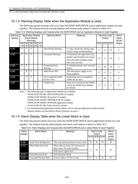
- Page 548 and 549: 10 Inspection, Maintenance, and Tro
- Page 550 and 551: 10 Inspection, Maintenance, and Tro
- Page 552 and 553: 10 Inspection, Maintenance, and Tro
- Page 554 and 555: 10 Inspection, Maintenance, and Tro
- Page 556 and 557: 10 Inspection, Maintenance, and Tro
- Page 558 and 559: 10 Inspection, Maintenance, and Tro
- Page 560 and 561: 10 Inspection, Maintenance, and Tro
- Page 562 and 563: 10 Inspection, Maintenance, and Tro
- Page 564 and 565: 11Appendix11.1 Servomotor Capacity
- Page 566 and 567: 11.1 Servomotor Capacity Selection
- Page 568 and 569: 11.1 Servomotor Capacity Selection
- Page 570 and 571: 11.1 Servomotor Capacity Selection
- Page 572 and 573: 11.1 Servomotor Capacity Selection
- Page 574 and 575: 11.1 Servomotor Capacity Selection
- Page 576 and 577: 11.1 Servomotor Capacity Selection
- Page 578 and 579: 11.1 Servomotor Capacity Selection
- Page 580 and 581: 11.2 Connection to Host Controller1
- Page 582 and 583: 11.2 Connection to Host Controller1
- Page 584 and 585: 11.2 Connection to Host Controller1
- Page 586 and 587: 11.2 Connection to Host Controller1
- Page 588 and 589: 11.2 Connection to Host Controller1
- Page 590 and 591: 11.3 List of Parameters11.3.2 List
- Page 592 and 593: 11.3 List of ParametersParameterNo.
- Page 594 and 595: 11.3 List of ParametersParameterNo.
- Page 596 and 597:
11.3 List of ParametersParameterNo.
- Page 598 and 599:
11.3 List of ParametersParameterNo.
- Page 600 and 601:
11.3 List of ParametersParameterNo.
- Page 602 and 603:
11.3 List of ParametersParameterNo.
- Page 604 and 605:
11.3 List of ParametersParameterNo.
- Page 606 and 607:
11.3 List of Parameters11.3.3 Monit
- Page 608 and 609:
11.4 Parameter Recording TableParam
- Page 610 and 611:
IndexINDEXAabsolute encoder battery
- Page 612 and 613:
IndexRrack-mounted type - - - - - -
- Page 614 and 615:
IndexWWARN- - - - - - - - - - - - -
- Page 616:
Series SGMH/SGDHUSER'S MANUALIRUMA


