Rotary Cutters & Slasher Manual.pdf - Farm Implements Australia
Rotary Cutters & Slasher Manual.pdf - Farm Implements Australia
Rotary Cutters & Slasher Manual.pdf - Farm Implements Australia
- No tags were found...

Create successful ePaper yourself
Turn your PDF publications into a flip-book with our unique Google optimized e-Paper software.
OPERATORS MANUAL&WARRANTY FORM<strong>Rotary</strong> <strong>Cutters</strong>Gavhall Pty Ltd, trading as KANGA FARM EQUIPMENT, would like to thank you for choosingone of our implements. Kanga <strong>Farm</strong> Equipment has manufactured three point linkage implementsto handle the harsh <strong>Australia</strong>n Conditions, since 1982.All new Kanga <strong>Farm</strong> Equipment <strong>Implements</strong> are backed with a 12 month comprehensive warranty,against faulty workmanship and/or materials, under normal working conditions and service, asoutlined in this manual. Your warranty may be considered void if any damage to the implement iscaused by operator abuse, neglect, or if any unauthorized modifications have been made.Kanga <strong>Farm</strong> Equipment and its Distributors/Dealers are not responsible for any transportationcost incurred in the repair or replacement of parts in either a successful or non-successfulwarranty claim. All implements must be returned to the manufacturer for warranty assessment.This warranty does not exclude any conditions implied by the Trade Practices Act 1974, or anyother relevant legislation.The information contained in this manual has been compiled to assist you with the implement thatyou have purchased. It is of the utmost importance that you read this manual, understand thecontext completely and carry out a risk assessment before operating the implement.Please be aware that in an effort to bring you better products we are always implementingcontinuous improvements that may change the designs and specifications of the implement. Indoing this, Kanga <strong>Farm</strong> Equipment together with its dealers and distributors are under noobligation to implement these changes, free of charge, on any previously delivered implement.Kanga - <strong>Rotary</strong> <strong>Cutters</strong> & <strong>Slasher</strong> <strong>Manual</strong>.docx16 Cahill Street, Dandenong, Victoria, <strong>Australia</strong>, 3175 Tel: (03) 9706 5166 Fax: (03) 9706 5050(PROP. GAVHALL PTY LTD)ACN 006 050 657ABN 59 918 752 500
TO THE DEALERAssembly and proper installation of this product is the responsibility of the KANGA FARM EQUIPMENT dealer. The dealer mustcomplete all items on the Warranty Registration & Installation Form included in this manual before releasing the implement to thenew owner.Both dealer and customer must sign the registration, which certifies that all Dealer Checklist items have been completed. The dealermust return a copy of the Warranty Registration & Installation Form to Kanga <strong>Farm</strong> Equipment. Reminders about WarrantyRegistration that have not been returned will be sent out to demonstrate that reasonable attempts have been made to ensure dealerscomplete risk assessment and pre-delivery obligations.TO THE OWNERRead this manual before operating your KANGA FARM EQUIPMENT implement. The information presented will prepare you todo a much better and safer job. This manual must stay with the <strong>Rotary</strong> Cutter in the “waterproof holder” (pictured on page 12) thatmust be permanently attached to the deck. Replacement manuals are available at www.farmimplements.com.au. Replacement“holders” are available through your nearest dealer.Ensure you carry out and keep up to date a Risk Assessment and that all operators read the manual carefully and become acquaintedwith all the adjustments and operating procedures before attempting to operate. Keep a record of the risk assessment and that theoperator has read and understands the correct operating procedures as outlined in this manual.The implement you have purchased has been carefully engineered and manufactured to provide dependable and satisfactory use. Likeall mechanical products, it will require routine cleaning, upkeep and maintenance. Lubricate the implement as specified. Observe allsafety information in this manual and safety decals on the implement.Throughout this manual the term IMPORTANT is used to indicate that a failure to observe can cause damage to the equipment. Theterms CAUTION, WARNING and DANGER are used in conjunction with the Safety-Alert Symbol (triangle with an exclamationmark) to indicate the degree of risk to your personal safety.This Safety-Alert Symbol indicates a hazard and means ATTENTION! BE CAREFUL! YOURSAFETY IS INVOLVED!DANGER indicates an imminently hazardous situation, which, if not avoided, will result in deathor serious injury.WARNING indicates a potentially hazardous situation, which, if not avoided, could result in deathor serious injury.CAUTION indicates a potentially hazardous situation, which, if not avoided, may result in minoror moderate injury. It may also be used to alert against unsafe practices.GENERAL INFORMATIONThe purpose of this manual is to assist you in operating and maintaining your KANGA <strong>Rotary</strong> Cutter. Read it carefully. It providesinformation and instructions that will help you achieve years of dependable performance. These instructions have been compiled fromextensive field experience and engineering data. Some information may be general in nature due to the unknown and varyingoperating conditions. However, through experience and these instructions, you should be able to develop procedures suitable to yourparticular situation.The illustrations and data used in this manual were current at the time of printing, but in an effort to bring you better products we arecontinuously implementing improvements that may vary your implement slightly in detail. We reserve the right to redesign andchange the machine as may be necessary without notice.Some illustrations in this manual show the <strong>Rotary</strong> Cutter with Safety Shields removed toprovide a better view. The <strong>Rotary</strong> Cutter should never be operated with any safety shieldingremoved.Throughout this manual, references are made to right and left direction. These are determined by standing behind the equipmentfacing the direction of forward travel. Blade rotation is anti-clockwise as viewed from the top of the Deck.2
SPECIFICATIONSS Range <strong>Rotary</strong> Cutter3 – Point Linkage … … … … … … … … … … … … … … … … … Category 1Body Thickness … … … … … … … … … … … … … … … … … 3mmTower Material … … … … … … … … … … … … … … … … … 75 x 16 FlatType of Tower … … … … … … … … … … … … … … … … … Double Clevis FloatingStays … … … … … … … … … … … … … … … … … … … … 10mm ChainChain working load (max) … … … … … … … … … … … … … … 3000 kgCutter Bar/Rotor^ … … … … … … … … … … … … … … … … … 100mm 3-Piece LaminatedCutter Bar/Rotor Material … … … … … … … … … … … … … … 10mm Spring SteelSkid Type … … … … … … … … … … … … … … … … … … … AdjustableSkid Side Material … … … … … … … … … … … … … … … … 6mmSkid Runner Material … … … … … … … … … … … … … … … … 12mmGearbox … … … … … … … … … … … … … … … … … … … 40hp (1:1.93 ratio)Tractor PTO Speed … … … … … … … … … … … … … … … … 540 rpmPower Take Off Shaft (PTO) … … … … … … … … … … … … … Series 4Clutch Size and Type° … … … … … … … … … … … … … … … … 6” Slip Clutch# Of Clutch Linings … … … … … … … … … … … … … … … … 2Blades^ … … … … … … … … … … … … … … … … … … … … Carbon/Chrome Spring SteelThickness of Blades … … … … … … … … … … … … … … … … 10mm# Of Blades … … … … … … … … … … … … … … … … … … … 2Model 1.2m (4’0”) 1.35m (4’6”) 1.5m (5’0”)Overall Width 1410mm 1556mm 1710mmCutting Width 1200mm 1350mm 1500mmCutting Height 25 – 100mm 25 – 100mm 25 – 100mmApproximate Weight 240 kg 270 kg 290 kgBlade Tip Speed (ft per min) 13,119 14,759 16,399 Specifications for this Gearbox can be found on page 27 of this Operators <strong>Manual</strong>.° Part Breakdown for the clutch can be found on page 22 of this Operators <strong>Manual</strong>.^ Part Breakdown of the Cutter Bar and Blades can be found on page 21 of this manual.5
SPECIFICATIONSM Range <strong>Rotary</strong> Cutter3 – Point Linkage … … … … … … … … … … … … … … … … … Category 1 & 2Body Thickness … … … … … … … … … … … … … … … … … 5mmCutter Bar/Rotor^ … … … … … … … … … … … … … … … … … 100mm 3-Piece LaminatedCutter Bar/Rotor Material … … … … … … … … … … … … … … 10mm Spring SteelSkid Type … … … … … … … … … … … … … … … … … … … AdjustableSkid Side Material … … … … … … … … … … … … … … … … 6mmSkid Runner Material … … … … … … … … … … … … … … … … 12mmGearbox … … … … … … … … … … … … … … … … … … … 75hp (1:1.46 or 1:1.93 )Tractor PTO Speed … … … … … … … … … … … … … … … … 540 rpmPower Take Off Shaft (PTO) … … … … … … … … … … … … … Series 6Clutch Size and Type° … … … … … … … … … … … … … … … … 8” Slip Clutch# Of Clutch Linings … … … … … … … … … … … … … … … … 2Blades^ … … … … … … … … … … … … … … … … … … … … Carbon/Chrome Spring SteelThickness of Blades … … … … … … … … … … … … … … … … 10mm# Of Blades … … … … … … … … … … … … … … … … … … … 2Model 1.5m (5’0”) 1.8m (6’0”) 2.1m (7’0”)Overall Width 1710mm 2010mm 2310mmCutting Width 1500mm 1800mm 2100mmCutting Height 25 – 100mm 25 – 100mm 25 – 100mmApproximate Weight 370 kg 470 kg 510 kgBlade Tip Speed (ft per min) 16,399 19,557 17,368Tower Material 90 x 16 Flat 90 x 16 90 x 16Type of Tower Double Clevis Floating Double Clevis Floating Double Clevis FloatingStays 13mm Chain 13mm 13mmChain working load (max) 4500 kg 4500 kg 4500 kg Specifications for this Gearbox can be found on page 28 of this Operators <strong>Manual</strong>. Specifications for this Gearbox can be found on page 28 of this Operators <strong>Manual</strong>.° Part Breakdown for the clutch can be found on page 22 of this Operators <strong>Manual</strong>.^ Part Breakdown of the Cutter Bar and Blades can be found on page 21of this manual.6
SPECIFICATIONSH Range <strong>Rotary</strong> Cutter3 – Point Linkage … … … … … … … … … … … … … … … … … Category 2 Double ClevisTower Material … … … … … … … … … … … … … … … … … 90 x 16Stays … … … … … … … … … … … … … … … … … … … … 13mm ChainChain working load (max) … … … … … … … … … … … … … … 4500 kgCutter Bar/Rotor^ … … … … … … … … … … … … … … … … … 130mm 3-Piece LaminatedCutter Bar/Rotor Material … … … … … … … … … … … … … … 10mm Spring SteelSkid Type … … … … … … … … … … … … … … … … … … … AdjustableSkid Side Material … … … … … … … … … … … … … … … … 8mmSkid Runner Material … … … … … … … … … … … … … … … … 16mmBlades^ … … … … … … … … … … … … … … … … … … … … Carbon/Chrome Spring SteelThickness of Blades … … … … … … … … … … … … … … … … 10mm# Of Blades … … … … … … … … … … … … … … … … … … … 2Model 1.8m (6’0”) 2.1m (7’0”)Body Thickness 6mm 6mmOverall Width 2034mm 2334mmCutting Width 1800mm 2100mmCutting Height 25 – 100mm 25 – 100mmApproximate Weight 585 kg 680 kgGearbox 130hp (1:1.93 ratio) 130hp (1:1.46 ratio)Tractor PTO Speed 540 rpm 540 rpmPower Take Off Shaft (PTO) Series 8 Series 8Clutch Size and Type° 8” Slip Clutch 8” Slip Clutch# Of Clutch Linings 4 4Blade Tip Speed (ft per min) 19,557 17,368 Specifications for this Gearbox can be found on page 29 of this Operators <strong>Manual</strong>. Specifications for this Gearbox can be found on page 29 of this Operators <strong>Manual</strong>.° Part Breakdown for the clutch can be found on page 22 of this Operators <strong>Manual</strong>.^ Part Breakdown of the Cutter Bar and Blades can be found on page 22 of this manual.7
Multi Head <strong>Rotary</strong> <strong>Cutters</strong>Due to the specific requirements of individual operators as dictated by their operating conditions, the information andspecifications about Kanga Multi Head <strong>Rotary</strong> <strong>Cutters</strong> in this manual maybe limited and general in nature. Kanga MultiHeads are custom built after consultation between the customer, the local dealer and a representative of Kanga <strong>Farm</strong>Equipment. Gearbox information and parts can be found on pages 27-31 while information and breakdown on theclutch(s) is on page 20 of this manual.Customers MUST carry their own Risk Assessment on every implement on their property.To achieve the desired end result that customers require of our Multi Head <strong>Rotary</strong> <strong>Cutters</strong> SOME Kanga MultiHead <strong>Rotary</strong> <strong>Cutters</strong> may not comply completely with the OH&S Industry Safety Standard for <strong>Slasher</strong>sreleased in February 2011. In this case Kanga <strong>Farm</strong> Equipment wishes to advise that Dealers and purchaserMUST carry out individual Risk Assessments for the implement PRIOR to operating.Pasture Topper3 – Point Linkage … … … … … … … … … … … … … … … … … Category 2 Double ClevisBody Thickness … … … … … … … … … … … … … … … … … 5mmBody Reinforcing … …. … … … … … … … … … … … … … … … 300mm Channel & RHS.Cutter Bar/Rotor … … … … … … … … … … … … … … … … … 100mm 3-Piece LaminatedCutter Bar/Rotor Material … … … … … … … … … … … … … … … … 10mm Spring SteelSkid Type … … … … … … … … … … … … … … … … … … … … … AdjustableBlades … … … … … … … … … … … … … … … … … … … … … Carbon/Chrome Spring SteelThickness of Blades … … … … … … … … … … … … … … … … … 10mmGearbox, PTO Shaft & Clutch … … … … … … … … … … … … … … Various (suited to tractor HP)50hp Orchard/Vineyard <strong>Rotary</strong> Cutter3 – Point Linkage … … … … … … … … … … … … … … … … … Category 1 Double ClevisBody Thickness … … … … … … … … … … … … … … … … … 3mmBody Reinforcing … …. … … … … … … … … … … … … … … … Angle and FlatCutter Bar/Rotor … … … … … … … … … … … … … … … … … 100mm 3-Piece LaminatedCutter Bar/Rotor Material … … … … … … … … … … … … … … … … 8mmSkid Type … … … … … … … … … … … … … … … … … … … … … AdjustableBlades … … … … … … … … … … … … … … … … … … … … … Carbon/Chrome Spring SteelThickness of Blades … … … … … … … … … … … … … … … … … 8mmGearbox … … … … … … … … … … … … … … … … … … … … … 50hpPTO Shaft … … … … … … … … … … … … … … … … … … … Series 4Clutch … … … … … … … … … … … … … … … … … … … … … 200mm (8”) 2 Plate75hp Orchard/Vineyard <strong>Rotary</strong> Cutter3 – Point Linkage … … … … … … … … … … … … … … … … … Category 2 Double ClevisBody Thickness … … … … … … … … … … … … … … … … … 5mmBody Reinforcing … …. … … … … … … … … … … … … … … … Angle and FlatCutter Bar/Rotor … … … … … … … … … … … … … … … … … 100mm 3-Piece LaminatedCutter Bar/Rotor Material … … … … … … … … … … … … … … … … 10mmSkid Type … … … … … … … … … … … … … … … … … … … … … AdjustableBlades … … … … … … … … … … … … … … … … … … … … … Carbon/Chrome Spring SteelThickness of Blades … … … … … … … … … … … … … … … … … 10mmGearbox … … … … … … … … … … … … … … … … … … … … … 75hpPTO Shaft … … … … … … … … … … … … … … … … … … … Series 6Clutch … … … … … … … … … … … … … … … … … … … … … 200mm (8”) 2 PlateTri-Head Orchard <strong>Rotary</strong> Cutter3 – Point Linkage … … … … … … … … … … … … … … … … … Category 2 Double ClevisBody Thickness … … … … … … … … … … … … … … … … … 5mmBody Reinforcing … …. … … … … … … … … … … … … … … … Angle/Flat/RHS.Cutter Bar/Rotor … … … … … … … … … … … … … … … … … 100mm 3-Piece LaminatedCutter Bar/Rotor Material … … … … … … … … … … … … … … … … 10mm Spring SteelSkid Type … … … … … … … … … … … … … … … … … … … … … AdjustableBlades … … … … … … … … … … … … … … … … … … … … … Carbon/Chrome Spring SteelThickness of Blades … … … … … … … … … … … … … … … … … 10mmGearbox, PTO Shaft & Clutch … … … … … … … … … … … … … … Various (suited to tractor HP)9
SAFETY RULES & ACCCIDENT PREVENTIONATTENTION! BE CAREFUL! YOUR SAFETY IS INVOLVED!Safety is a primary concern in the design and manufacturing of our products. Unfortunately, our efforts to provide safeequipment can be wiped out by a single careless act of an operator.In addition to the design and configuration of equipment, hazard control and accident prevention are dependent upon theawareness, concern, prudence and proper training of personnel involved in the operation, transport, maintenance andstorage of equipment.It has been said, “The best safety device is an informed careful operator.” We ask you to be that kind of operator.Customers MUST carry their own Risk Assessment and/or “HazCheck” on every implement on their property.Safety instructions are important! Read all attachments and unit manuals; follow all safety rules and safety decalinformation. Failure to follow instructions can result in serious injury or death.If you do not understand any part of this manual and need assistance the Department of Agriculture, OccupationalHealth & Safety Offices, any Agricultural School or college and your local dealer should be able to direct you on whereyou can receive appropriate training. No operator however experienced in farm machinery operation they maybe,should attempt to use any piece of machinery that they have not been competently trained to use.Keep hands and body away from pressurized lines. Use paper or cardboard, not hands or other body parts to check forleaks. Wear safety goggles. Hydraulic fluid (oil) under pressure can easily penetrate the skin and will cause seriousinjury or death.Make sure that all operating and service personnel know that if hydraulic fluid (oil) penetrates the skin, it must besurgically removed as soon as possible by a doctor familiar with this form of injury or gangrene, serious injury or deathwill result. CONTACT A PHYSICAN IMMEDIATELY IF FLUID ENTERS SKIN OR EYES. DO NOT DELAY.Know your controls and how to stop quickly in an emergency.Operators must be instructed in and be capable of the safe operation of the equipment and all controls. Do not allowanyone to operate this equipment without proper instruction.Do not allow children or untrained persons to operate equipment.Check that all hardware (nuts, bots, etc.) are tight and properly installed.Always wear relatively tight fitted clothing to avoid entanglement in moving parts. Wear heavy-duty, rough-soled bootsand protective equipment for eyes, hair, hands, hearing and head.Ensure implement is properly attached, adjusted and in a good condition so that it can be operated safely.Make sure all spring activated locking pins or collars on the Power Take Off (PTO) Shaft move freely, are well greasedand are firmly seated in the tractor PTO splined angular groove.Before commencing operation, check all equipment driveline guards for damage and make sure they rotate freely.Replace any damaged guards or guards that do not rotate freely on drivelines.Tractors MUST be fitted with Roll Over Protection Structure (ROBS) or ROBS Cap. It is also advisable that yourtractor be fitted with a seatbelt. Where fitted it must be worn at all times. Falling from your tractor can result in deathfrom being run over or crushed. If your tractor is fitted with a folding ROBS, keep it in the “locked up” position at alltimes.Inspect chains, shackles, deflectors and any wear parts for damage. Replace if damaged.Remove any debris that has accumulated on the implement, tractor or engine to avoid fire hazard.Ensure your tractor has a fire extinguisher and ensure you know how to use the extinguisher in the event of anemergency.Ensure all safety decals are installed. Replace if damaged.Ensure shields and guards are properly installed and in good working condition. Replace if damaged.Do not operate implement unless side skids are in good condition. Replace if damaged.A minimum 20% of tractor and equipment weight must be on the tractor’s front wheels with implement in the transportposition. Without this weight, tractor could tip over causing personal injury or death. The weight may be attained witha loader, front wheel weights, and ballast in the tyres or front tractor weights. When attaining the minimum 20% weighton the front wheels, you must not exceed the ROPS max ballasted mass certificate. Weigh the tractor and implement.Do not estimate.Watch for hidden hazards on the terrain during operation and avoid any hazards or objects that could cause injury ordamage.Inspect operating areas and remove any foreign objects that could be thrown, causing injury or damage. It is veryimportant to always watch for foreign objects when you are operating and avoid them as they can cause injury ordamage.10
When operating along roads, pathways or populated areas fit extra chains or shielding (which is designed to reduce thepossibility of objects being thrown) to the implement. If the implement is missing or has damaged shielding, operationmust not continue until guarding has been repaired.When working in populated areas always place signs in the area to alert people or vehicles that may pass.Keep all people and animals away from the implement during start up, operating and when stopping.Never discharge directly toward people, animals or property.Disconnect the PTO when raising the slasher above working height.Do not operate the implement or tractor while under the influence of drugs or alcohol.Operate only in daylight or good artificial light.Keep hands, feet, hair, and clothing away from moving parts while engine is running.Do not carry persons or objects on the Implement or tractor during work or while in transit.For transportation on public roads the operator must ensure that the tractor and implement complies with current Stateand Federal laws and must strictly adhere to all road traffic regulations in force in his/her particular state.Always operate equipment from the seat of the tractor with the seat belt securely fastened, especially when operatingcontrols or starting engine. Place transmission in neutral, engage break and ensure all other controls are disengagedbefore starting tractor engine.Operate tractor PTO at 540 rpm speed as stated in “Specifications” section unless you have purchased a Multi-Head andrequested 1000rpm. Always ensure the correct setting on your tractor before start up.Do not operate tractor PTO during transport or when implement is raised above normal working height.Look down and to the rear and make sure area is clear and safe before operating in reverse.Do not operate on steep slopes. If in doubt set rear axles wider for moderate slopes.Do not stop, start or change directions suddenly on slopes’, working up and down is preferred.Use extreme care and reduce ground speed on slopes and rough terrain.Stop implement, then tractor, immediately upon striking an obstruction. Turn off engine, remove key, inspect and repairany damage before resuming operations. Always block implement when inspecting.Before commencing any adjustment, maintenance, or cleaning, always disengage the Power Take Off (PTO) Shaft,switch off the tractor engine, remove key and wait until all moving parts have come to a complete stop, then ensure themachine is on the ground or on a robust, secure support.Before dismounting tractor or performing any service or maintenance, disengage power to implement, lower the 3-pointlinkage and any other raised components (i.e. loader bucket) to the ground. Operate valve levers to release any hydraulicpressure, stop engine, set parking brake, remove key and unfasten seat belt.Disconnect driveline from the tractor PTO before performing any service work.Never place any part of the body underneath the implement or between moveable parts even when engine has beenturned off. Hydraulic systems can “creep” (i.e. slowly lower). They may fail, or movement of the control levers can causethe implement to drop or rotate unexpectedly causing severe injury or death. Follow Operator’s <strong>Manual</strong> instructions forworking on your implement or have servicing carried out by a qualified dealer.During routine checks and/or repairs ensure that no one can switch on the tractor or Implement accidentally. Keep thekey to the tractor in your pocket.For your own safety and that of others and to avoid forfeiting your warranty, use only original spare parts.Do not modify/alter or permit anyone else to modify/alter the implement or any of its components.Ensure implement is properly attached, adjusted and in good operating condition.Frequently check blades. They should be sharp, free of nicks and cracks and securely fastened.Do not handle blades with bare hands. Careless or improper handling may result in serious injury.Always use genuine Kanga Blades. Your dealer can supply you with genuine replacement blades.Firmly tighten all nuts/bolts/screws/shackles before operating. If worn or damaged, replace immediately.Block implements securely for storage.Keep children and bystanders away from storage area.Kanga <strong>Farm</strong> Equipment accepts no responsibility or liability for any losses, injuries or damages that may result fromfailing to observe these safety rules and the safety decals on the implement.11
SAFETY RULES & ACCCIDENT PREVENTIONATTENTION! BE CAREFUL! YOUR SAFETY IS INVOLVED!Decal Layout…Replace any damaged or un-readable decals immediately.Please contact your nearest Kanga <strong>Farm</strong> Equipment Dealer should you require replacement decalsfor your implement.Below is a picture of the “waterproof holder” where your manual must be stored. The holdermust be permanently fixed to the deck with the manual inside to satisfy OH&S legislation thatwas introduced in 2011.If the manual holder is damaged in any way, please contact you nearest dealer and arrange areplacement.Replacement Order Code:100.141 – <strong>Manual</strong> Holder12
OPERATIONSafety is a primary concern in the design and manufacturing of our products. Unfortunately, our efforts to provide safeequipment can be wiped out by a single careless act of an operator.In addition to the design and configuration of equipment, hazard control and accident prevention are dependent upon theawareness, concern, prudence and proper training of personnel involved in the operation, transport, maintenance andstorage of equipment.It has been said, “The best safety device is an informed careful operator.” We ask you to be that kind of operator.The operator is responsible for the safe operation of this implement. The Operator must be properly trained. Operatorsshould be familiar with the implement and tractor and all safety practices before starting operation. Read the safety rulesand safety decal information on pages 10, 11 & 12.Customers MUST carry their own Risk Assessment and/or “HazCheck” on every implement on their property.Do not allow children or untrained persons to operate this implement.Keep all people and animals away from the implement during start up, operating and when stopping.Never place any part of the body underneath the implement or between moveable parts even when engine has beenturned off. Hydraulic systems can “creep” (i.e. slowly lower). They may fail or movement of the control levers can causethe implement to drop or rotate unexpectedly causing severe injury or death. Follow Operator’s <strong>Manual</strong> instructions forworking on your implement or have servicing carried out by a qualified dealer.During routine checks and/or repairs ensure that no one can switch on the tractor or Implement accidentally. Keep thekey to the tractor in your pocket.Make sure all spring activated locking pins or collars on the Power Take Off (PTO) Shaft move freely, are well greasedand are firmly seated in the tractor PTO splined angular groove.Watch for hidden hazards on the terrain during operation and avoid any hazards or object that could cause injury ordamage.Inspect operating areas and remove any foreign objects that could be thrown, causing injury or damage. It is veryimportant to always watch for foreign objects when you are operating and avoid them as they can cause injury ordamage.When operating along roads, pathways or populated areas fit extra chains or shielding (which is designed to reduce thepossibility of objects being thrown) to the implement. If the implement is missing or has damaged shielding, must notcontinue until it has been repaired.When working in populated areas always place signs in the area to alert people or vehicles that may pass.Stop implement, then tractor, immediately upon striking an obstruction. Turn off engine, remove key, inspect and repairany damage before resuming operations. Always block implement when inspecting.Always wear relatively tight fitted clothing to avoid entanglement in moving parts. Wear heavy-duty, rough-soled bootsand protective equipment for eyes, hair, hands, hearing and head.A minimum 20% of tractor and equipment weight must be on the tractor’s front wheels with implement in transportposition. Without this weight, tractor could tip over causing personal injuryor death. The weight maybe attained with a loader, front wheel weights, andballast in the tyres and/or front tractor weights. When attaining theminimum 20% weight on the front wheels, you must not exceed the ROPSmax ballasted mass certificate. Weigh the tractor and implement. Do notestimate.Figure: Tractor Stability13
ATTACHING TO THE IMPLEMENTWhen connecting the tractor to the Implement never stand in between the tractor and the Implement andalways find somewhere level or flat.Always adjust the tractor lower linkage arms anti-sway devices to prevent implement from swing from sideto side during transport and operation. Failure to do so may result in serious injury or damage. Damagesuch as bent and twisted implement towers are consumable items and are NOT covered by warranty.Line the tractor up so that the double clevis mounting point on the implement can be connected to the lower link arms ofthe tractor and secure with lynch pins. Attach tractor top link to implement top double clevis with top hitch pin andsecure with lynch pin. Always ensure that the tractor connection (lower arms or top link) are not outside the doubleclevis mounting point.The Power Take Off Shaft (PTO)PTO shafts come in standard lengths so that they can be adapted to all tractors. This means that you may have toshorten the PTO Shaft to suit your tractor. Failure to shorten your PTO shaft may result in “End Thrust.”“End Thrust” can destroy your tractors internal drive and/or the <strong>Slasher</strong>s Clutch and/or <strong>Slasher</strong> Gearbox.This damage will not be covered by warranty.To shorten your shaft, please follow the steps below.14
Always wear relatively tight fitted clothing to avoid entanglement in moving parts. Wear heavy-duty,rough-soled boots and protective equipment for eyes, hair, hands, hearing and head when carrying out anyservicing or operational tasks.Always check the plastic guarding on PTO shaft and the plastic clutch cover on the gearbox. If worn or damagedreplace immediately. Make sure all spring activated locking pins or collars on the Power Take Off (PTO) Shaft move freely, arewell greased and are firmly seated in the tractor PTO splined angular groove.To secure the PTO to the tractor you will see that there is a spring activated locking pin on both ends of the PTO Shaft.Push this pin in and slide the PTO onto either the tractor output shaft or the implement input shaft. Continue to slide thePTO onto the shaft until it becomes firmly seated in the angular groove. Always ensure that both ends are locked intothe angular groove before engaging the PTO Shaft.Depending on the model of tractor that is being used with the implement it may be possible to raise theimplement to a point where the PTO fouls on the frame of the implement. This can bend your PTO shaftand may cause serious injury or damage. When commencing operations slowly raise the implement via thelinkage. If the PTO shaft looks like it will touch before the linkage reaches the maximum lift, then set a“STOP” on the tractors hydraulic lower linkage arms so that the operator cannot go past this point duringoperation, do not commit it to memory.Check the specified PTO speed for your implement and ONLY operate in that range.Your PTO shaft and the safety covers do comply with AS1121.4 and as a result it will be clearly labeled withinstructions to show which end should be fitted to the tractor and which should be fitted to the implement. Please followthe labels carefully so that you do not void your warranty.To avoid damage to the covers of your PTO Shaft always slowly lower the shaft onto the deck of the slasher whendisconnecting it from your tractor. To prevent damage and for longevity when the implements is not in use alwaysremove the PTO shaft from the clutch and store in a cool dry place.15
IMPORTANTCutting Height AdjustmentAvoid low cutting heights. Striking the ground with blades produces one of the most damaging shock loads a <strong>Slasher</strong> canencounter. Allowing blades to repeatedly make contact with the ground will cause damage to the <strong>Slasher</strong> and drivelines(i.e. PTO Shaft).Keep all persons away from operators control area while performing adjustments, service or maintenance.During routine checks and/or repairs ensure that no one can switch on the tractor or Implement accidentally. Keep thekey to the tractor in your pocket.The <strong>Rotary</strong> Cutter should be operated at the highest position that will give the desired cutting result. This will helpprevent the blades striking the ground, reducing blade wear and undue strain on the implement. For best results underheavier cutting conditions, always tilt the implement so that the front is 25-50mm lower. This tilt decreases thehorsepower requirements and increases potential ground speed. When fine cutting is desired, adjust the implement sothe deck is level or slightly lower in the rear. This will keep the foliage under the cutter until thoroughly shredded.Operating in this manner will require more horsepower and a slower ground speed to get the desired result.Never place any part of the body underneath the implement or between moveable parts even when engine has beenturned off. Hydraulic systems can “creep” (i.e. slowly lower). They may fail or movement of the control levers can causethe implement to drop or rotate unexpectedly causing severe injury or death.Follow Operator’s <strong>Manual</strong> instructions when working on your implement or have servicing carried out by a qualifieddealer.Before commencing any adjustment, maintenance, or cleaning, always disengage the Power Take Off (PTO) Shaft,switch off the tractor engine, remove key and wait until all moving parts have come to a complete stop. Then ensure themachine is on the ground or on a robust secure support.The minimum cutting height will vary depending on the slasher you have purchased. Generally the minimum height isaround 40mm and there are four (4) hole settings (approx. 30mm apart) giving you several height positions and amaximum cut height around 170mm). Always ensure that the slasher is level by making sure every bolt is set in thesame height position.To adjust the height of your skids you will need to remove the bolt, adjust the implement to the desired height, andreplace bolt and spring washer before securing the nuts tightly.If you have a depth wheel fitted then the height is adjustable from approx. 40mm to 300mm. For safety reasons youmust not remove the adjustable skids. It is good practice to set the adjustable skids at the minimum cut height. This willallow you a full range of height adjustment for the depth wheel and should the hydraulics on the tractor fail for anyreason, will stop the cutter bar from hitting the ground and hence protect your gearbox.To allow you a greater range of adjustment the Depth Wheel brackets have many holes. Like operating without awheel, you should always ensure the back of the slasher is 25-50 higher than the front. This is important not only for thequality of the cut but also for the depth wheel. The wheel needs to be able to work like a “shopping trolley” and canonly do so if the back is higher.Storage and TransportTo increase the longevity of your Kanga <strong>Rotary</strong> Cutter, we suggest you try and store it undercover in a dry place out ofthe weather. This will reduce the amount of regular maintenance you will need to preform on the <strong>Rotary</strong> Cutter over themany years you are likely to own it.If you cannot store your Kanga <strong>Rotary</strong> Cutter undercover, then we suggest you store it in a defined “machinery” areawell away from animals, people and other machinery. If possible try and store the <strong>Rotary</strong> Cutter on a slight incline (ordecline. As your <strong>Rotary</strong> Cutter has a clean top deck design a slight angle will allow any rain water to run off and as aresult should increase the life of your <strong>Rotary</strong> Cutter.When choosing a place to disconnect and leave your <strong>Rotary</strong> Cutter always make sure the skids are sitting on firm stableground. This will make it a lot easier to reattach the <strong>Rotary</strong> Cutter next time you need to use it. And always remove thePTO shaft and store it separately so PTO covers do not get damaged.16
When transporting your <strong>Rotary</strong> Cutter always make sure the power to the <strong>Rotary</strong> Cutter has been turn off at the tractorand that the slasher is far enough off the ground that it cannot come in contact with the ground.NEVER TRANSPORT YOUR ROTARY CUTTER WITH BLADES/BLADE BEANS ROTATING!NEVER TRANSPORT YOUR ROTARY CUTTER ON ROADS WITH THE SKIDS TOUCHING THE GROUND!Always slow your speed on rough and uneven ground or roads. Always make sure your tractor and implementcomplies with current State and Federal laws and ensure you strictly adhere to all road traffic regulations in force in yourparticular state.Daily Pre-Operation Checklist(Owners Responsibility)□□□□□□□□□□□□□□□Operators MUST carry out a Risk Assessment and/or “HazCheck” for the implement and ensure it is correctfor the conditions the implement will be operating.Review and follow safety rules outlined in this manualCheck Waterproof <strong>Manual</strong> Holder is attached to the deck and manual is in good condition insideCheck that implement is properly and securely attached to the tractorMake sure PTO spring activated locking pin is well greased, sides freely and is firmly seated in tractor PTOsplined angular groove.Set tractor PTO at 540 rpm (Some Multi-Heads may have been designed for 1000rpm).Lubricate all grease fitting locations. Make sure PTO joints and shaft is well lubricated.Check oil runs out the small level plug on the side of the gearbox.Check all hardware (i.e. bolts, nuts, shackles, chains, etc.) are properly installed, secured and in goodcondition.Check blades are sharp and secure and cutting edge is positioned to lead when rotating anti-clockwise.Check that all shields and guards are properly installed and in good conditionCheck cutting height, front to rear attitude and top link adjustment.Set friction clutch as outlined in “Owner Service” section of this manual.Ensure tractor PTO and transmissions are in neutral before starting engine.Inspect area that you will be operating in and remove any object that may cause injury or damage.IMPORTANTSet friction clutch as outlined in “Owner Service” section of this manual.Vibration tends to loosen bolts during operation. All hardware should be checked regularly. It is goodpractice to check implement before each operation to ensure all hardware is secure.17
Operating TechniquePower for operating a <strong>Rotary</strong> Cutter is supplied by tractor PTO. The decal on the implement will indicate the correctsetting. In many cases this will be 540 rpm but operators MUST always double check. Know how to stop tractor andslasher quickly in case of emergency. Always make sure the correct PTO setting is selected before starting the tractor.Set up your implement for the type of finish you are looking for as specified in the “Cutting Height Adjustment” onpage 16 of this manual, then return to the tractor seat, fasten seat belt, make sure tractor is in neutral and all othercontrols are disengaged before starting tractor engine.With the <strong>Rotary</strong> Cutter lowered, start tractor engine and engage PTO while the tractor engine has low rpm to minimizestress on the driveline and gearbox. With PTO engaged, raise engine rpm until PTO speed is 540 rpm (or 1000rpm onsome Multi Head <strong>Rotary</strong> <strong>Cutters</strong>). Maintain throughout cutting operation.Gearbox protection is provided by a slip clutch with replaceable discs. The slip clutch is designed to slip whenexcessive torque loads are encountered. Always make sure the clutch is set and working correctly before operating.Move into material slowly with the <strong>Rotary</strong> Cutter. Adjust tractor ground speed to provide a clean cut without strainingthe tractor engine. If tractor engine is straining, reduce amount of material being cut by taking a narrower pass. Groundspeed will depend upon the terrain, the height, type and density of the material being cut. Normal ground speed willrange from four to eight kph (two to five mph). Tall dense material should be cut at low speed; thin medium-heightmaterial can be cut at a faster ground speed. Use a slow ground speed for finer cuttingAlways operate tractor PTO at 540rpm (1000 for some Multi Heads) as specified in the “Specifications.” This isnecessary to maintain proper blade speed and produce a clean cut. A slower PTO speed will result in blades and bushesmoving around due to the low centrifugal, which will lead to excessive wear.Under certain conditions, tractor tyres may roll some grass down and prevent it from being cut at the same height as thesurrounding area. When this occurs reduce ground speed, but maintain either 540 or 1000rpm at the PTO. The slowerground speed will at least give the grass time to partially rebound and get cut.Under some conditions, grass will not rebound enough to be cut evenly. In general, lower cutting heights give a moreeven cut with fewer tendencies to leave tire tracks. However, it is better to cut grass frequently rather than too short.Short grass deteriorates rapidly in hot weather and invites weed growth during growing seasons.Inspect operating areas and remove any foreign objects that could be thrown. It is veryimportant to always watch for foreign objects when you are operating and avoid them asthey can cause injury, damage and in extreme situations death.Extremely tall material should be cut twice. Set <strong>Rotary</strong> Cutter at a higher cutting height for the first pass. Then for thesecond pass cut at desired height, 90 to the first pass. Remember, sharp blades produce a cleaner cut and require lesshorsepower.Analyze area to be cut to determine the best procedure. Plan your operating pattern to travel straight forward wheneverpossible. Mow clockwise around fields when possible to minimize streaking on corners. Consider height and type ofgrass and terrain type: hilly, level, rough. Always allow for the effect that the weight of an implement has on the tractorparticularly on hilly or unstable terrain. It is recommended that in hilly situations you work straight up and down notacross the slope.Do not operate on steep slopes, if in doubt set rear axles wider or only operate on moderate slopes.Do not stop, start or change directions suddenly on slopes, working up and down is recommended.Use extreme care and reduce ground speed on slopes and rough terrain.Pass diagonally through sharp dips and avoid sharp drops to prevent “hanging up” tractor and slasher. Practice willimprove your skills in maneuvering on rough terrain18
Removing Cutter from TractorIt is more than likely that you will have the implement in the transport position and therefore the PTO should already bedisengaged. Never transport the implement with the PTO engaged. Lower implement and all attachments (i.e.loader buckets) all the way to the ground and wait for all moving parts to come to a complete stop. Turn off tractorignition and remove key. Firmly apply park brake, remove seatbelt and dismount the tractor. Remove check chains (ifinstalled). Disconnect the PTO Shaft from the tractor by de-pressing spring activated locking pin(s) and slowly lowerPTO Shaft onto the deck to avoid damage to the safety covers. Next, disconnect PTO shaft from the implement (againby de-pressing spring-activated locking pin(s)) and collapse PTO Shaft insides itself as far as possible. Put aside so afteryou have disconnected the implement you can store PTO in a dry area undercover. Block implement securely forstorage with robust secure supports then remove top and lower linkage pins. Make sure that the tractor’s lower linkagearms are free and return to tractor seat. Start tractor as specified in the tractors operating manual, select a low gear andslowly drive away from the implement making sure that it does not fall. Collect PTO shaft and store safely in dryundercover area.OWNER SERVICEThe information in this section is written for operators who possess basic mechanical skills. Should you need help, yourdealer has trained service technicians available. For your protection, read and follow safety information in this manual.Disengaged tractor PTO and wait for all moving parts to come to a complete stop. Lower implement to the ground orblock with secure robust support. Turn tractor engine off, remove key and disconnect PTO Shaft from the tractorbefore performing any service or maintenance.Keep all persons away from operator control area while performing adjustments, service or maintenance.During routine checks and/or repairs ensure that no one can switch on the tractor or Implement accidentally. Keep thekey to the tractor in your pocket.Always wear relatively tight fitted clothing to avoid entanglement in moving parts. Wear heavy-duty, rough-soled bootsand protective equipment for eyes, hair, hands, hearing and head.Blocking MethodTo minimize the potential hazards of working underneath the implement, these procedures must be followed.Never go underneath implements that are lowered to the ground or raised, unless it is properly blocked and secure.Never place any part of the body underneath the implement or between moveable parts even when engine has beenturned off. Hydraulic systems can “creep” (i.e. slowly lower). They may fail or movement of the control levers can causethe implement to drop or rotate unexpectedly causing severe injury or death. Follow Operator’s <strong>Manual</strong> instructions forworking on your implement, correct blocking procedures or have servicing carried out by a qualified dealer.During routine checks and/or repairs ensure that no one can switch on the tractor or Implement accidentally. Keep thekey to the tractor in your pocket.Jack stands with a load rating of 1250lbs (560kg) PLUS are the only approved blocking devices for this implement. Aminimum of four (4) jack stands, located under the implement as shown by the “X’s” on page 20, must be installedbefore working underneath the implement. Do not position jack stands under wheels, axles or wheel supports ascomponents can rotate and cause implement to fall.When blocking, you must consider the overall stability of the implement. Just placing jack stands under the unit will notensure your safety. The working surface must be level and solid to support the weight of the jack stands. Ensure jackstands are stable both top and bottom, and implement is approximately level. With full implement weight lowered ontojack stands, test blocking stability before beginning working underneath implement.Implement should be properly and securely attached to the tractor (see operating section), the brakes firmly set, keyremoved and both front and rear tractor wheels securely blocked.19
Lubrication InformationDo not let excess grease collect on or around parts, particularly when operating in sandy conditions.The figures below show the lubrication points and give the frequency of lubrication in normal operating hours based onnormal operating conditions. Severe or unusual conditions may require more frequent lubrication..When greasing implement, be sure to clean fittings thoroughly before attaching grease gun. Kanga <strong>Farm</strong> Equipmentrecommends Lithium Grease with a #2 consistency for all locations, unless otherwise noted.Kanga <strong>Farm</strong> Equipment, in conjunction with the gearbox manufacturer recommends high quality gear oil with aviscosity index of 90W. Fill gearbox until oil runs out the side plug on the gearbox. Check gearbox daily for evidenceof leakage. Have your dealer assist you should you find evidence of leakage.Lubricate the PTO universal joint every eight operating hours. Failure to maintain proper lubrication could result indamage to universal Joints, gearbox and driveline. To lubricate the shaft itself, lower implement to the ground,disconnect PTO Shaft from tractor and slide the PTO halves out until almost disconnected from each other. Apply abead of grease completely around male half where it meets the female half. Slide over each other several timesrepeatedly to distribute grease.Cutter Bar and Blade ServicingIt will be necessary to gain access to the bottom side of the slasher to change the blades. Disconnect PTO Shaft from thetractor, raise implement and block securely as outlined in this manual, before changing the blades.Remove nuts and then carefully remove blade bolt. If blade bolt is seized in the cross bar, to prevent gearbox damage, itmay be necessary to completely unbolt rotor before driving the old bolt out.Always replace or sharpen both blades at the same time. Inspect blade bolts for nicks and gouges; replace if any arefound. Insert blade bolt through lower part of the blade beam, then through the blade with the hardened bush inserted.Finally insert through the top part of the blade beam and secure with Nyloc Nut. Blade should swivel on the bolt.Determine cause if it does not and correct (i.e. maybe nut too tight).IMPORTANTBlade beam rotation is anti-clockwise when looking down on the slasher. Be sure to install blade cuttingedge to lead in an anti-clockwise direction.When sharpening blades grind each blade the same amount to maintain balance. Replace blades in pairs.Unbalanced blades will cause excessive vibration that can damage gearbox bearings. Vibration may alsocause structural cracks to the implement and/or gearbox housing.20
The ClutchKanga 150mm (6”) Two Plate Slip Clutch1) 1 3 / 8 ” x 6 Spline base assembly (includes bush)2) Bush 1 1 / 8 ” ID3) Friction Disc 5” OD x 1 3 / 4 ” ID (2 required)4) 1 3 / 8 ” x 6 Spline Drive Plate5) Pressure Plate6) Spring (6 required)Kanga 200mm (8”) Two Plate Slip Clutch1) 1 3 / 8 ” x 6 Spline base assembly (includes bush)2) Bush 1 1 / 8 ” ID3) Friction Disc 6 1 / 2 ” OD x 2 1 / 2 ” ID (2 required)4) 1 3 / 8 ” x 6 Spline Drive Plate5) Outer Pressure Plate6) Spring (8 required)Kanga 200mm (8”) Four Plate Slip ClutchKanga 200mm (8”) Six Plate Slip Clutch1) 1 3 / 4 ” x 20 Spline base assembly. High Tensile Casting5 / 8 ” Clamp bolts2) Bush to suit 1 3 / 4 ” x 20 Spline base3) Friction Disc 6 1 / 2 ” OD x 2 1 / 2 ” ID (4 required)4) 1 3 / 8 ” x 6 Spline Drive Plate5) Intermediate Pressure Plate 1 3 / 8 ” x 6 Spline6) Outer Pressure Plate (2 required)7) Spring (8 required)1) 1 3 / 4 ” x 20 Spline base assembly. High Tensile Castingwith 5 / 8 ” Clamp bolts2) Bush to suit 1 3 / 4 ” x 20 Spline base3) Friction Disc 6 1 / 2 ” OD x 2 1 / 2 ” ID (6 required)4) 1 ¾” x 20 Spline Drive Plate5) Intermediate Pressure Plate 1 ¾” x 20 Spline6) Outer Pressure Plate (3 required)7) Spring (8 required)22
Setting the ClutchGearbox protection is provided by a slip clutch with replaceable discs. The slip clutch is designed to slip and whenexcessive torque loads are encountered.All new clutches supplied with Kanga <strong>Farm</strong> Equipment implements have been pre set by the following guide.1. Compress springs fully then back off two (2) turns.2. Fine tune so that the clutch slips occasionally.On 20 spline models, clutch retaining (clamp) bolts must be tightened to 150 ft/lbs to clamp clutch to shaft - LOOSEBOLTS = STRIPPED SPLINES.NT: Discs are approximately 3.2mm thick when new. Replace discs after 1.6mm of wear. Minimum discthickness is 1.6mm.A new slip clutch, or one that has been in storage for some time, may be seized. Annually, release springs completelyand allow clutch to slip to polish pressure plate then fine tune so clutch slips. To do this you will have to carry out thefollowing operations:Make sure tractor is turned off and key is removed.Remove PTO Shaft from the tractor.Loosen the bolts to remove all tension from the springs.Wedge the blade beam so that it cannot rotate.Grab PTO Shaft or clutch input shaft and turn to make sure clutch slips.If clutch does not slip freely, disassemble and clean the face of the clutch pressure plates and spline base assembly.Reassemble clutch.Tighten each bolt evenly until the springs are compressed, then back off all nuts two (2) full turns.If clutch continues to slip then tighten each bolt half a turn at a time until clutch is no longer slipping.If springs are compressed to 24mm, check friction discs for excessive wear. Discs are approximately 3.2mm thickwhen new. Replace discs after 1.6mm of wear. Minimum disc thickness is 1.6mm.Every individual is operating in a slightly different environment with a range of variables that determine how the clutchmust be set for their operation. The size of the tractor, the size of implement and the work being carried out and theterrain are all factors that determine the clutch setting. A quarter or half a turn can make a big difference. It is for thisreason that each clutch should be reset for your operating conditions.Shielding RepairWhen operating along roads, pathways or populated areas fit extra chains or shielding (which is designed toreduce the possibility of objects being thrown) to the implement. If the implement is missing or hasdamaged shielding, operation must not continue until it has been repaired.When working in highly populated areas always place signs in the area to alert people or vehicles that maybe passing.Your implement will be fitted with Chain Guards or Shielding. It is important to inspect the guarding everyday prior tooperation. Should there be any visible signs of wear or damage, repair or replace required parts and ensure guarding isin an “as new” condition before commencing operations.23
PTO Shaft – Lubrication & Maintenance Information24
ProblemGrass cut is lower in the centerthan on the edges.<strong>Slasher</strong> is “Streaking” (i.e. notcutting cleanly.)Material discharged from slasheris uneven and in clumps.TROUBLE SHOOTINGGRASS CUTTINGPossible CausesHeight of the slasher is lower atthe front or rear.Conditions too wet for cutting.Blades unable to cut the grassthat the tractor tyres presseddown.Blunt Blades.Material being cut is too longand/or has too much volume.Grass is too wet.Rear of slasher is too low,trapping material underneath.SolutionAdjust height and ensure frontand rear of the slasher are within20mm of the same height. Seeinstructions.Allow grass to dry before cutting.Reduce ground speed butmaintain maximum rpm at thetractor PTO as specified in“Specifications.” And/or, lowercutting height.Sharpen or replace blades.Reduce ground speed butmaintain maximum rpm at thetractor PTO as specified in“Specifications” or make twopasses. First pass higher than thesecond and the second at 90 tothe first.Allow grass to dry before cutting.Reduce ground speed butmaintain maximum rpm at thetractor PTO as specified in“Specifications.”Adjust slasher height and ensurefront and rear of the slasher arewithin 20mm of the same height(see instructions.).<strong>Slasher</strong> will not cut all the timeand the clutch smokes when it’snot cutting.Slip clutch is slipping.Adjust slip clutch according toinstructions in the “OwnerService” section of this manual.25
GEARBOX SERVICEThe information in this manual requires special skills and tools. If you are not properly equipped or your mechanics arenot properly trained in this type of repair, you may void your warranty or cause more damage leading to a larger repairbill.Never place any part of the body underneath the implement or between moveable parts even when enginehas been turned off. Hydraulic systems can “creep” (i.e. slowly lower). They may fail or movement of thecontrol levers can cause the implement to drop or rotate unexpectedly causing severe injury or death.Follow Operator’s <strong>Manual</strong> instructions for working on your implement or have servicing carried out by aqualified dealer.During routine checks and/or repairs ensure that no one can switch on the tractor or Implementaccidentally. Keep the key to the tractor in your pocket.Keep all persons away from operator control area while performing adjustments, service or maintenance.Always wear relatively tight fitted clothing to avoid entanglement in moving parts. Wear heavy-duty,rough-soled boots and protective equipment for eyes, hair, hands, hearing and head.Gearbox MaintenanceDuring routine checks and/or repairs ensure that no one can switch on the tractor or Implementaccidentally. Keep the key to the tractor in your pocket.Keep all persons away from operator control area while performing adjustments, service or maintenance.Do not carryout any servicing on the gearbox if it has been operating. Gearboxes and the oil inside are veryhot during operations and for sometime after you have finished and can cause serious burns. Always waitfor gearbox to cool down.Fill gearbox with high quality gear oil with a viscosity index of 90W. Fill gearbox until oil runs out the side plug on thegearbox. Gearbox Oil should be changed every 1000 hours of use or every two (2) years. Always drain oil into acontainer and dispose of it properly to protect the environment.Oil level must be checked daily. The composition of oil deteriorates over time and the intense heat that occurs whenoperating a gearbox reduces the oil level. Low oil levels will result in wear of gearbox components that overtime willresult in component failure that could have been prevented.Repair to this gearbox should be limited to replacing bearings, seals and gaskets. Replacing gears, shafts and a housingis not cost effective. It is more economical to purchase a complete gearbox if repairs other than bearings, seals andgaskets are required. It is highly recommended that the customer be given the costs involved in both scenarios as a newgearbox comes with a new warranty (gearbox only).Inspect gearbox for leakage and bad bearings. Leakage is a very serious problem and must be corrected immediately.Excessive noise and side to side or endplay in the shafts indicate bearing failure. Leakage can occur at the vertical orhorizontal gasket and shaft seals. Leakage from the horizontal gasket or seal can be repaired without removing thegearbox from the slasher.Proper seal installation is important. An improperly installed seal will leak. Always ensure the area where the sealsouter diameter sits is clean. Always inspect the area of the shaft where the seal sits and remove any burrs or nicks withan emery cloth. Always lubricate gear shaft and seal lips before assembling. Remove and replace any seals damagedduring assembly.When assembling gearboxes always clean housing paying specific attention to areas where gaskets will be installed.Wash housing and all components thoroughly. Select a clean area where you can assemble the gearbox. Replace anydamaged seals, bearings or gaskets. All parts must be clean and lightly oiled before being reassembled.26
Part # 100.414 - 50hp Hi-Speed GearboxAll Mini Range <strong>Rotary</strong> <strong>Cutters</strong>Part # 100.312 – 40hp GearboxAll S Range <strong>Rotary</strong> <strong>Cutters</strong>Housing: 60-45-10 NodularShafts: UNS G51200Gears: UNS G51200Seals: Triple lipped spring loadedBearings: Deep groove ballOil: EP-90, 0.77LWeight: 22.8 kgInput shaft: 1 3 / 8 x 6 SplineRotation:1) Housing2) Spacing Sleeve3) Retaining ring (3 used)4) Matched set of gears (1:1.93 ratio)5) Rear bearing6) Input shaft7) Input gasket8) Retaining ring9) Input Seal10) Input cap11) Bearing (3 used)12) Output gasket13) Lower seal housing14) Output seal15) Hub16) Flat washer17) 1” x 14 TPI castellated nut27
Part # 100.212 - 75hp Gearbox (1:1.46)2100 (7’-0”) <strong>Rotary</strong> <strong>Cutters</strong>Housing (all 75hp): 60-45-10 NodularShafts & Gears (all 75hp): UNS G51200Seals (all 75hp):Triple lipped spring loadedBearings (all 75hp): Tapered rollerOil (all 75hp): EP-90, 1.12LWeight (all 75hp): 37.2 kgInput shaft (all 75hp): 1 3 / 8 x 6 SplineRotation (all 75hp):1) Main Housing2) Output shaft3) Bearing cone top and bottom4) Bearing cup top5) 13 tooth output pinion (1:1.46 ratio)6) Input Shaft (1 3 / 8 x 6 Spline)7) Cup and cone assembly (2 used)8) Retaining Ring9) 19 tooth input pinion (1:1.46 ratio)10) Shim gasket (use quantity as required)11) Spacer12) Input seal13) Input Cap14) Shim gasket15) Lower seal housing16) Output seal17) Hub18) Flat washer (1” ID)19) 1” x 14 TPI castellated nut20) Breather Plug21) Bottom bearing cupPart # 100.213 - 75hp Gearbox (1:1.93)1500 (5’-0”) & 1800 (6’-0”) <strong>Rotary</strong> <strong>Cutters</strong>1) Main Housing2) Spacing tube3) Bearing cone top and bottom4) Bearing cup top5) 15 tooth output pinion (1:1.93ratio)6) input shaft (1 3 / 8 x 6 Spline)7) cup and cone assembly (2 used)8) Retailing ring9) 29 tooth input pinion (1:1.93 ratio)10) shim gasket (use quantity as required)11) spacer12) input seal13) input cap14) shim gasket (use quantity as required)15) lower seal housing16) output seal17) hub18) flat washer (1” ID)19) 1” x 14 TPI castellated nut20) bottom bearing cup28
Part # 100.108 - 130hp Gearbox (1:1.467 ratio) 2100 (7’-0”) <strong>Rotary</strong> <strong>Cutters</strong> & Multi headsPart # 100.109 - 130hp Gearbox (1:1.92 ratio) 1800 (6’-0”) <strong>Rotary</strong> <strong>Cutters</strong> & Multi headsPart # 100.142 – 130hp Gearbox (1.888:1 Reduction) Multi head <strong>Cutters</strong>Part # 100.143 – 130hp Gearbox (1:1 ratio) Multi Head <strong>Cutters</strong>Housing: 60-45-10 NodularShafts: UNS G51200Gears: UNS G51200Seals: Triple lipped spring loadedBearings: Tapered rollerOil: EP-90, 1.5LInput shaft: 1 3 / 4 x 20 SplineOutput shaft: 60mm dia.Rotation:1. Input seal2. Output seal3. Output gear 13 tooth 17 spline (1:1.467 ratio)a. Output gear 13 tooth 25 spline (1:1.92 ratio)b. Output gear 19 tooth (1.888:1 reduction ratio)c. Output gear 17 tooth (1:1 ratio)4. Input gear 19 tooth (1:1.467 ratio)a. Input gear 25 tooth (1:1.92 ratio)b. Input gear 16 tooth (1.888:1 reduction ratio)c. Input gear 17 tooth (1:1 ratio)5. Input shaft6. Output shaft (1:1.92 ratio)7. Output shaft (all other model)8. Output hub9. Lower output nut10. Top output nutMulti Head GearboxesThe Gearboxes in this section are used in conjunction with the right angle gearboxes pictured in pages 24-26 of this manual, theClutches are on page 20 and several different combinations of Rubber and Spring Cushion Couplings (page 28) may be used.For more information on Couplings please contact us.Part # 100.144 - 50hp “T” Gearbox (1:1 Ratio)Part # 100.145 – 50hp “T” Gearbox (1:1.5 Ratio)Used on 50hp Orchard/Vineyard <strong>Rotary</strong> <strong>Cutters</strong> with 50hp Hi-Speed Gearbox29
Part # 100.146 - 80hp “T” Gearbox (1:1 Ratio)Used on 75hp Orchard/Vineyard <strong>Rotary</strong> <strong>Cutters</strong> & Pasture Topper1) Oil Seal2) Breather Plug3) Output Gasket Shim4) 17 Tooth Gear (2 req.)5) Circlip6) Main Housing7) Cup/Cone Bearing (2 req.)8) Through Shaft9) Bearing Cup (2 req.)10) Bearing Cone (2 req.)11) Input Shaft12) Input Seal13) Input Cap14) Input Gasket Shim15) CapPart # 100.147 - 90hp “T” Gearbox (1:1.5 Ratio)Used on 75hp Orchard/Vineyard <strong>Rotary</strong> <strong>Cutters</strong> & Pasture Topper1) Input Seal2) Output Seal3) Through Shaft4) Input Gear5) Output Gear6) Input ShaftPart # 100.147 - 150hp “T” Gearbox (1:1 Ratio)Part # 100.148 – 150hp “T” Gearbox (1:1.5 Ratio)Used on 75hp Orchard/Vineyard <strong>Rotary</strong> <strong>Cutters</strong> & Pasture Topper30
Part # 100.150 - 150hp “4-WAY” Gearbox (1.888:1 Reduction Ratio)Part # 100.151 - 150hp “$-WAY” Gearbox (1:1.467 Ratio)Part # 100.152 - 150hp “$-WAY” Gearbox (1:1.92 Ratio)Housing:Shafts:Gears:Seals:Bearings:Oil:60-45-10 NodularUNS G51200UNS G51200Triple lipped spring loadedTaper RollerEP-901/ Input Oil Seal 2/ Through Shaft Oil Seal3/ Through Shaft 4/ Input Gear5/ Output Gear 6/ Input Shaft7/ Outer Bearing (input and cross shafts)8/ Rear Bearing (input shaft)9/ Bearing (output shaft) 2 required10/ Slotted Nut (1 3/8” x 18 UNF)Part # 100.153 – Male Spring Coupling (1 3 / 8 x 6 Spline Anticlockwise)Part # 100.154 – Male Spring Coupling (1 3 / 8 x 6 Spline Clockwise)Part # 100.157 – Male Spring Coupling (1 ¾ x 20 Spline Anticlockwise)Part # 100.158 – Male Spring Coupling (1 ¾ x 20 Spline Clockwise)1/ Cotter Bolt – Fits 1 ¾” x 20 Spline single cotter bolt coupling2/ Base – 1 3 / 8 ” x 6 SplineBase – 1 ¾” x 20 Spline3/ Spacing Collar4/ Outer Spider Plate5/ Drive Spring (8 req.)6/ Inner Spider (1 3 / 8 ” x 6 Spline)Inner Spider (1 ¾” x 20 Spline)7/ Bearing (suit both Spiders)8/ Bearing HousingPart # 100.155 – Female Spring Coupling (1 3 / 8 x 6 Spline Anticlockwise)Part # 100.156 – Female Spring Coupling (1 3 / 8 x 6 Spline Clockwise)Part # 100.159 – Female Spring Coupling (1 ¾ x 20 Spline Anticlockwise)Part # 100.160 – Female Spring Coupling (1 ¾ x 20 Spline Clockwise)1/ Cotter Bolt – Fits 1 ¾” x 20 Spline single cotter bolt coupling2/ Base – 1 3 / 8 ” x 6 SplineBase – 1 ¾” x 20 Spline2a/ Freewheel Base - 1 3 / 8 ” x 6 Spline (Anticlockwise)Freewheel Base - 1 3 / 8 ” x 6 Spline (Clockwise)3/ Spacing Collar4/ Outer Spider Plate5/ Drive Spring (8 req.)6/ Inner Spider (1 3 / 8 ” x 6 Spline)Inner Spider (1 ¾” x 20 Spline)7/ Bearing (1 3 / 8 ” x 6 Spline)Bearing (1 ¾” x 20 Spline)8/ Bearing Housing (1 3 / 8 ” x 6 Spline)Bearing Housing (1 ¾” x 20 Spline)At the time of printing, the importer of some gearboxes and couplings(pages 25 & 29), did not have spare part breakdowns and parts list available.For more information and parts on this gearbox please contact us.We are very sorry for any inconvenience this may have caused.31
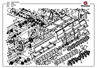
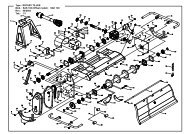
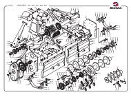
ASSEMBLY INSTRUCTIONSDepending on the location of the dealer the implement may be shipped partly assembled or in parts, in any case theassembly of this implement is the responsibility of the KANGA FARM EQUIPMENT dealer. It should be delivered tothe new owner completely assembled, lubricated and adjusted for normal cutting conditions.Dealers please note that, even if the implement is delivered to you fully assembled, an authorized companyrepresentative with mechanical knowledge should still carryout the pre-delivery checks to ensure that nothing has comeloose in transit.Final assembly should result in the <strong>Rotary</strong> Cutter looking like the photos pictured earlier in this manual.Operators who own a Kanga <strong>Rotary</strong> Cutter with “MULTI-MOUNT” Tower, should always ensure that thetower is set to the desired position before the implement is connected to the tractor.Do not under any circumstances try and change the tower position while the <strong>Rotary</strong> Cutter is connected to thetractor. Doing so could cause damage to the implement or serious injury to the operator.IMPORTANTMake sure all spring activated locking pins or collars on the Power Take Off (PTO) Shaft move freely, arewell greased and are firmly seated in the tractor PTO splined angular groove.Operate tractor PTO at 540-rpm (1000rpm for some Multi Heads) as stated in “Specifications” section.Firmly tighten all nuts, bolts, screws and shackles before operating. Check equal tension on chain stays.When operating along roads, pathways or populated areas fit approved Kanga chains or rubber shielding(which is designed to reduce the possibility of objects being thrown) to the implement. If this implementdoes not have chains or rubber shielding, operation must be stopped when anyone comes within 100 meters.When working in highly populated areas always place signs in the area to alert people or vehicles that maybe passing.Always wear relatively tight fitted clothing to avoid entanglement in moving parts. Wear heavy-duty,rough-soled boots and protective equipment for eyes, hair, hands, hearing and head.Parts DiagramsMini Range <strong>Rotary</strong> <strong>Cutters</strong>32
S Range <strong>Rotary</strong> <strong>Cutters</strong>M Range <strong>Rotary</strong> <strong>Cutters</strong>XH/H Range <strong>Rotary</strong> <strong>Cutters</strong>33
Agricultural Machinery Product OHS Compliance FormWe,Of,Gavhall Pty Ltd t/as Kanga <strong>Farm</strong> Equipment16 Cahill StreetDandenong, Victoria, <strong>Australia</strong>, 3175Telephone: 03-9706-5166Fax: 03-9706-5050Confirm that the following machine(s)Kanga Mini Range <strong>Rotary</strong> <strong>Cutters</strong>Kanga S Range <strong>Rotary</strong> <strong>Cutters</strong>Kanga M Range <strong>Rotary</strong> <strong>Cutters</strong>Kanga H Range <strong>Rotary</strong> <strong>Cutters</strong>Kanga XH Range <strong>Rotary</strong> <strong>Cutters</strong>Kanga 50hp Orchard/Vineyard <strong>Rotary</strong> <strong>Cutters</strong>Kanga 75hp Orchard/Vineyard <strong>Rotary</strong> <strong>Cutters</strong>Kanga Pasture ToppersKanga Tri-Head Orchard <strong>Rotary</strong> <strong>Cutters</strong>have had a hazard identification, risk assessment and risk control procedure carried out on a representative model of theaforementioned product(s) in accordance with the Occupational Health and Safety requirements of all states andterritories of <strong>Australia</strong> and where found necessary the appropriate risk control measures have been incorporated in theproduct specifications.The Operators <strong>Manual</strong> contains the necessary Health and Safety information and safety warnings decals are applied tothe product where necessary.Product Description: <strong>Rotary</strong> <strong>Cutters</strong> / <strong>Slasher</strong>sModel Number(s): XH Range – Product Code(s) 19000, 19500, 20000, 20500H Range – Product Code(s) 21500, 22000M Range – Product Code(s) 25000, 26000, 27000S Range – Product Code(s) 29000, 30000, 31000Mini Range – Product Code(s) 32750, 32850Pasture Topper – Product Code(s) 33000, 34000, 34100, 3415050hp Orchard/Vineyard <strong>Rotary</strong> Cutter – Product Code(s) 39400, 39500, 3960075hp Orchard/Vineyard <strong>Rotary</strong> Cutter – Product Code(s) 38000, 38500, 39000Tri-Head Orchard <strong>Rotary</strong> Cutter – Product Code(s) 34190, 34200, 34210Name:Bruce J AlcottPosition Managing Director Date: 07 / 04 / 2008Details of the unit assessed for the purpose of compliance were:Model # Size Serial # Date of Inspection LocationMini Range 1000 1040408 02 / 04 / 2008 16 Cahill St, DandenongS Range 1200 1060408 02 / 04 / 2008 16 Cahill St, DandenongM Range 1500 1300408 02 / 04 / 2008 16 Cahill St, DandenongH Range 1800 1030408 02 / 04 / 2008 16 Cahill St, DandenongXH Range 1800 1020408 02 / 04 / 2008 16 Cahill St, DandenongPasture Topper 3000 130208 26 / 02 / 2008 16 Cahill St, Dandenong50hp Orchard/Vineyard 1350 520306 22 / 03 / 2006 16 Cahill St, Dandenong75hp Orchard/Vineyard 2400 220906 14 / 09 / 2006 16 Cahill St, DandenongTri-Head Orchard 3600 190407 16 / 04 / 2007 16 Cahill St, Dandenong34
PRE-DELIVERY CHECKLIST(Dealers Responsibility)Inspect implement thoroughly after assembly to be certain it is set up properly before delivering it to the customer. Thefollowing checklist is a reminder of points to inspect. Check off each item as it is found satisfactory either before orafter corrections or services performed.Check all bolts to be sure that they are tightCheck all cotter pins are properly installed and secureCheck PTO series is correct and that the PTO is the correct lengthIMPORTANTGearbox was not filled with oil at the factory. It must be serviced beforeimplement is operated or it will result in damage to the gearbox. You will find a level plug on the side of yourgearbox or a guide to the amount of oil required can be found on the same page as the gearbox parts guide.Check gearbox is properly serviced and seals are in good condition and not leaking.Refer to lubrication instructions and lubricate implement.Check that blades have been properly installed.Show customer how to make adjustments. Describe the options available for the implement and explain theirpurpose and how they work.Explain the importance of lubrication to the customer and point out all the lubrication points on the implement.Point out the safety features, especially the rubber belt shielding or chains are fitted and how to maintain them.Ensure the stability of the tractor has not been compromised with the implement the customer has purchased.Remember a minimum 20% of tractor and equipment gross weight must be on the tractor’s front wheels with theimplement in the transport position. If you are adding weight to the tractor to attain the 20%, you must not exceedthe ROPS max ballasted mass certificate. Weigh the tractor and implement. Do not estimate.Ensure the manual is in the waterproof holder and that the holder is not damaged. Ensure the customer knows thatthe manual is to stay with the cutter at all times and that replacement manuals can be downloaded atwww.farmimplements.com.au. Instruct the customer to become familiar with all sections, especially the safety andsafe operating procedures and ensure anyone using the cutter has read (and understands) the contents of the manual.Explain to the customer that when transporting the implement on roads or highways, day or night, safety devicesshould be used to provide adequate warning to operators of other vehicles. Also explain the operator must ensurethat the tractor and implement complies with current State and Federal laws and must strictly adhere to all roadtraffic regulations in force in his/her particular state.Instruct the customer that they MUST carry out a Risk Assessment and/or HazCheck for the implement and theiroperating conditions.Ensure the customer has signed the WARRANTY REGISTRATION & INSTALLATION FORM and a copyhas been returned to Kanga <strong>Farm</strong> Equipment, 16 Cahill Street, Dandenong, Victoria, 3175.Name of person who carried out Pre-delivery: ______________________ Signature: ___________________Dealership Name: ________________________ Location carried out: _______________________________Date:_ _ / _ _ / _ _ _ _Top copy (manufacture) Middle Copy (dealer) Last page (purchaser)35
WARRANTY REGISTRATION & INSTALLATION FORMOwners Name: _ _ _ _ _ _ _ _ _ _ _ _ _ _ _ _ _ _ _ _ _ _ _ _ _ _ _ _ _ _ _ _ _ _ _ _ _ _ _ _ _ _ _ _ _ _ _Town: _ _ _ _ _ _ _ _ _ _ _ _ _ _ _ _ _ _ _ _ _ _ _ _ _ _ _ State: _ _ _ _ _ _ _ _ _ _ _ _ P/Code: _ _ _ _Single Gearbox <strong>Rotary</strong> CutterModel Mini S Range M Range H Range XH RangeMultiply Gearbox <strong>Rotary</strong> CutterModel Pasture Topper 50hp Vineyard 75hp Vineyard Tri Head CustomSize 1000mm 1200mm 1350mm 1500mm 1800mm 1900mm 2100mm 2400mm 3000mm 3600mm 4100mm 4500mm Custom __________________Serial Number ___________________Month of Manufactured: Jan Feb Mar Apr May Jun Jul Aug Sept Oct Nov DecYear of Manufacture _ _ _ _Date of Purchased _ _ / _ _ / _ _ _ _Intended use: Paddocks Only Close to Sheds/Buildings/Roads (Y / N). If yes, comprehensive Risk Assessment. Contracting, please specify: _ _ _ _ _ _ _ _ _ _ _ _ _ _ _ _ _ _ _ _ _ _ _ _ _ _ _ _ _ _ _ _ _ _ _ (comprehensive Risk Assessment). Other, please specify: _ _ _ _ _ _ _ _ _ _ _ _ _ _ _ _ _ _ _ _ _ _ _ _ _ _ _ _ _ _ _ _ _ _ _ _ _ _ _ _ _ _ _ _ _ _ _ _ _ _ _I have been fully instructed in the operation of this unit in the actual working conditions that I intend to operate and I am satisfied that Ican use it safely. I acknowledge that I have been fully instructed in the care, maintenance, lubrication and that Kanga <strong>Rotary</strong> <strong>Cutters</strong>have been designed to cut long grass on agricultural properties away from people, animals, roads and property. I understand that Ineed to maintain guarding and carry out visual inspections (removing foreign objects) on any area that I intend to operate. Iunderstand that I MUST carry out a Rick Assessment for the implement for all the different conditions and locations I intended tooperate. I have received a copy of the operating manual and the dealer has instructed me to read the manual in full and carry out myRisk Assessment before commencing any operations._ _ _ _ _ _ _ _ _ _ _ _ _ _ _ _ _ _ _ / _ _ / _ _ _ _O w n e r’ s S i g n a t u r e.D a t e FINAL ASSEMBLY – Checked all hardware to ensure it is firmly tightened as outlined in the Operators <strong>Manual</strong> and instructed customer on howto make regular checks and tighten ALL hardware. LUBRICATION – The implement has been lubricated and oil levels have been checked in all chain/gearbox transmissions and customer hasbeen instructed on how to check oil levels and lubricate implement. GREASING & MAINTENANCE – Grease bearings, universals and all PTO shaft parts. Instruct customer on how to re-grease the implement.Explain to the operator the requirements and repercussions if not regularly maintained. IMPLEMENT, DRIVESHAFT & TRACTOR COMPATIBILITY – Check implement and PTO compatibility with purchases tractor.Ensure PTO shaft is the correct length and will not foul on the tractor or implement during linkage operation. If PTO was cut make sure that it wasre-greased and all spring activated locking pins on the PTO Shaft move freely. CLUTCH ADJUSTMENT – Check that clutch has been correctly fitted and nuts are tight. Instruct the customer that clutch needs to be finetuned for the customer’s situation. Instruct customer that an annual service is required. OPERATION PROCEDURES – Instruct the operator on correct procedures and techniques for the type of work they have indicated they intendto carry out. General safe operating procedures can be found in the Operators <strong>Manual</strong>. Advise customer they MUST carry out a risk assessmentand hazard identification of the property and alert the customer to the type of potential dangers they should be looking to avoid. SHIELDING – Instruct the customer that if they wish to operate the implement along roads, pathways or in populated areas near people, animalsor vehicles that they MUST carry out a comprehensive Risk Assessment to reduce their exposure to litigation. DANGERS – Instruct the customer on the potential dangers of operating the implement. Outline the dangers associated with rotating blades, thepossibility of fast moving debris, rotating PTO Shaft and ensure the customer knows that information about safe operating procedures andmaintenance are in this <strong>Manual</strong>. OWNERS/OPERATORS MANUAL – Check that the implement has a booklet supplied. Emphasize the importance of reading the <strong>Manual</strong>.Note manuals can be down loaded from www.farmimplements.com.au RISK ASSESSMENT – Ensure you inform customer to complete HazCheckNT: As some Multi Head <strong>Rotary</strong> <strong>Cutters</strong> may not comply with the OH&S publication “<strong>Slasher</strong>s: A guide on health and safety standards” datedFebruary 2011, dealers MUST complete a HazCheck in conjunction with the customer on these implements. As part of the HazCheck it is highlyrecommended you cover all points from Appendix B – Pre-Purchase Checklist of the OH&S publication AND you keep a SIGNED COPY of theHazCheck!Please tick the boxes above as each point has been carried out.Dealership Name: _ _ _ _ _ _ _ _ _ _ _ _ _ _ _ _ _ _ _ _ _Pre-delivered By: _ _ _ _ _ _ _ _ _ _ _ _ _ _ _ _ _ _ _ _Salesperson’s Name: _ _ _ _ _ _ _ _ _ _ _ _ _ _ _ _ _ _ _ _ Salesperson’s Signature: _ _ _ _ _ _ _ _ _ _ _ _ _ _ _ _ _Top copy (manufacture) Middle Copy (dealer) Last page (purchaser)36