Dielectric, ferroelectric and piezoelectric properties of sputtered PZT ...
Dielectric, ferroelectric and piezoelectric properties of sputtered PZT ...
Dielectric, ferroelectric and piezoelectric properties of sputtered PZT ...
- No tags were found...

You also want an ePaper? Increase the reach of your titles
YUMPU automatically turns print PDFs into web optimized ePapers that Google loves.
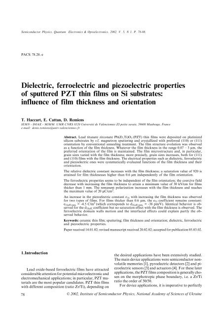
Semiconductor Physics, Quantum Electronics & Optoelectronics. 2002. V. 5, N 1. P. 78-88.PACS: 78.20.-e<strong>Dielectric</strong>, <strong>ferroelectric</strong> <strong>and</strong> <strong>piezoelectric</strong> <strong>properties</strong><strong>of</strong> <strong>sputtered</strong> <strong>PZT</strong> thin films on Si substrates:influence <strong>of</strong> film thickness <strong>and</strong> orientationT. Haccart, E. Cattan, D. RemiensIEMN - DOAE - MIMM. UMR CNRS 8520 Université de Valenciennes ZI petite savate, 59600 Maubeuge, Francee-mail: denis.remiens@univ-valenciennes.frAbstract. Lead titanate zirconate Pb(Zr,Ti)O 3 (<strong>PZT</strong>) thin films were deposited on platinizedsilicon substrates by r.f. magnetron sputtering <strong>and</strong> crystallized with preferred (110) or (111)orientation by conventional annealing treatment. The film structure evolution was observedas a function <strong>of</strong> the film thickness. Whatever the film thickness in the range 0.07 – 3 µm, thepreferred orientation <strong>of</strong> the film is maintained. The film microstructure <strong>and</strong>, in particular,grain sizes varied with the film thickness; more precisely, grain sizes increases, both for (111)<strong>and</strong> (110) films with the film thickness. The electrical <strong>properties</strong> such as dielectric, <strong>ferroelectric</strong><strong>and</strong> <strong>piezoelectric</strong> ones were systematically evaluated functions <strong>of</strong> the film thickness <strong>and</strong> theirorientation.The relative dielectric constant increases with the film thickness; a saturation value <strong>of</strong> 920 isattained for film thicknesses higher than 0.6 µm independently <strong>of</strong> the film orientation.The <strong>ferroelectric</strong> <strong>properties</strong> seems to be independent <strong>of</strong> the film orientation; the coercive fielddecrease with increasing the film thickness to attain a minimum value <strong>of</strong> 30 kV/cm for filmsthicker than 1 mm. The remanent polarization increases with the film thickness <strong>and</strong> reachesthe maximum value <strong>of</strong> 20 µC/cm 2 .An increase in the <strong>piezoelectric</strong> constant e 31 with increasing the film thickness was observedfor two types <strong>of</strong> films. For films thicker than 0.6 µm, the e 31 coefficient remains constant:e 31eff.rem. = -4.5 C/m 2 (which corresponds to d 31eff.rem. = -38 pm/V). Identical behavior is observedfor the d 33eff. coefficient but no saturation effect with the film thickness is observed. The<strong>ferroelectric</strong> domain walls motion <strong>and</strong> the interfacial effects could explain partly the observedbehavior.Keywords: ceramic thin film; sputtering; film thickness <strong>and</strong> orientation; dielectric, <strong>ferroelectric</strong><strong>and</strong> <strong>piezoelectric</strong> <strong>properties</strong>.Paper received 14.01.02; revised manuscript received 20.02.02; accepted for publication 05.03.02.1.IntroductionLead oxide-based <strong>ferroelectric</strong> films have attractedconsiderable attention for potential microelectronic <strong>and</strong>electromechanical applications; in particular, <strong>PZT</strong> materialsare the most popular c<strong>and</strong>idates. <strong>PZT</strong> thin filmswith different composition (ratio Zr/Ti), depending on78the desired applications have been extensively studied.The main device applications were semiconductor nonvolatilememories [1], pyroelectric detectors [2] <strong>and</strong> <strong>piezoelectric</strong>sensors [3] <strong>and</strong> actuators [4]. For these laterapplications, the <strong>PZT</strong> films composition is generally chosenon the morphotropic phase boundary, i.e. a Zr/Tiratio the order <strong>of</strong> 50/50.For device applications, it is imperative to perfectly© 2002, Institute <strong>of</strong> Semiconductor Physics, National Academy <strong>of</strong> Sciences <strong>of</strong> Ukraine
T. Haccart et al.: <strong>Dielectric</strong>, <strong>ferroelectric</strong> <strong>and</strong> <strong>piezoelectric</strong> <strong>properties</strong>...know the influence <strong>of</strong> the film characteristics such as:- the structure (epitaxial or polycrystalline films withpreferred orientation)- the microstructure (grain size) <strong>and</strong> the interfaces,- the thickness, …on the electrical <strong>properties</strong>. For example, for MicroElectro Mechanical Systems (MEMS) applications, thefilm thickness must be in the order <strong>of</strong> 1 µm or more [5]; onthe contrary, for nonvolatile memories, the film must bevery thin 6 (0.2 – 0.3 µm). It is evident that the thicknessmust have a strong influence on the film electrical <strong>properties</strong>.The structure <strong>and</strong> the microstructure <strong>of</strong> <strong>PZT</strong> filmswere controlled by many parameters: the growth technique,the substrate nature <strong>and</strong> orientation, the presence<strong>of</strong> a seed layer or an electrode surface. The electrodesurface has the function to decrease the nucleation energyfor a given crystallographic orientation <strong>of</strong> the nucleus.It has been clearly established that the formation<strong>of</strong> the perovskite phase was nucleation controlled. Thefilm orientation <strong>and</strong> thickness have also an influence onthe physical <strong>properties</strong>, <strong>and</strong> it is necessary to preciselyevaluate this dependence in order to improve the deviceperformance.Many authors have described the influence <strong>of</strong> <strong>PZT</strong>films orientation on their electrical <strong>properties</strong> but the resultswere in many cases in contradiction. For example,we can find in the literature that (111)-oriented <strong>PZT</strong> filmsare higher coercive field than (100) films, but the oppositesituation has been also published [7,8]. Identical situationfor the film thickness effect 9,10 was ascertained. Concerningthe evaluation <strong>of</strong> the <strong>piezoelectric</strong> coefficientse 31 , d 31 <strong>and</strong> d 33 dependence with the <strong>PZT</strong> film thicknessthere is a limited number <strong>of</strong> papers [11,12].So, in this article we have systematically studied <strong>PZT</strong>films deposited by r.f. magnetron sputtering followed bya post-annealing treatment on Pt metallized siliconsubstrates:-the influence <strong>of</strong> the film thickness on their structural<strong>and</strong> micro structural <strong>properties</strong>,-the influence <strong>of</strong> the film thickness <strong>and</strong> orientation ontheir electrical <strong>properties</strong>: dielectric, <strong>ferroelectric</strong> <strong>and</strong><strong>piezoelectric</strong>.Some tentative behavior explanations are made, <strong>and</strong>a correlation between the electrical <strong>properties</strong> <strong>and</strong> themicrostructure by the way <strong>of</strong> the existence <strong>of</strong> an interfaciallayer between the film <strong>and</strong> the substrate as well asthe domain walls motion is given.2. Film deposition <strong>and</strong> characterizationThe r.f. magnetron sputtering system, described previously[13], was used to prepare <strong>PZT</strong> thin films; the filmscomposition, i.e. the (Zr/Ti) ratio, was fixed to 54/46(near the morphotropic phase boundary). It is well knowthat in the bulk ceramics the best <strong>piezoelectric</strong> performanceis obtained for this composition.The sputtering target was a mixture <strong>of</strong> PbO, TiO 2 <strong>and</strong>SQO, 5(1), 2002ZrO 2 in the stoichiometric composition (without lead excess);the targets were obtained by uniaxially cold pressing.The <strong>PZT</strong> films were deposited onto oxidized silicon(SiO 2 - 3000 Å)- (100) n-type Si substrates coated with Ti/Pt electrodes. The thickness <strong>of</strong> the Ti <strong>and</strong> Pt layers was100 <strong>and</strong> 1500 Å, respectively. More precisely, we havedeposited an oxydized titanium, i.e. TiO x , layer as anadhesion film for the Pt layer on SiO 2 . The main objectiveis to limit the diffusion <strong>of</strong> titanium through Pt; it iswell known that the diffusion velocity <strong>of</strong> TiO x is lowerthan Ti; then this procedure can stabilize the substrateduring the <strong>PZT</strong> crystallization post-annealing treatment.With the same idea (stabilization <strong>of</strong> the substrate), justbefore the <strong>PZT</strong> deposition, we have made an annealingtreatment <strong>of</strong> the Si/SiO 2 /TiO x /Pt substrates at a temperaturehigher to the post-annealing <strong>PZT</strong> treatment. A morecomplete description <strong>of</strong> the substrate preparation is givenelsewhere [14]. Hence, with this precaution, we can supposethat the substrates used in this experiment are similar<strong>and</strong> stable. But, as we can see later, this is not the case<strong>and</strong> the <strong>PZT</strong> films orientation can varied between twodepositions run. We think that only the substrate <strong>and</strong>, inparticular, the bilayers TiO x /Pt can be responsible forthis modification. More complete studies are necessaryto underst<strong>and</strong> the substrate evolution, which appearsduring the annealing treatment <strong>of</strong> the <strong>PZT</strong> films.Table. Typical sputtering parameters for the <strong>PZT</strong> films growth<strong>and</strong> post-annealing conditions.Target composition Zr/Ti = 54/46 –without lead excessTarget diameter (mm) 76r.f.power density ( W /cm 2 ) 3Gas pressure (mT)30 (Ar)Interelectrodes distance (mm) 60Substrate temperature (°C) 25-140(ion bombardment)Annealing temperature (°C) 625Annealing time (min.) 30AtmosphereAirThe <strong>PZT</strong> sputtering conditions are summarized inTable 1; they are optimized in order to obtain a stoichiometricfilm (measured by Energy DispersionSpectroscopy) <strong>and</strong> a relatively important growth rate (foran oxide material). It was estimated to 30 Å/min; forhigher r.f. power density (which influence strongly thegrowth rate) some cracks appear on the target, in particular,in the erosion area (magnetron system). The filmswere grown without substrate heating <strong>and</strong> so they areamorphous; a post-annealing treatment is necessary tocrystallize the <strong>PZT</strong> in the desired phase, i.e. in theperovskite phase.We have been optimized two processes [15]:- the conventional annealing in a tubular furnace,- the rapid thermal annealing .79
T. Haccart et al.: <strong>Dielectric</strong>, <strong>ferroelectric</strong> <strong>and</strong> <strong>piezoelectric</strong> <strong>properties</strong>...Pt [ 111]Pt [ 111]e= 2.1 µ me= 0.03 µ mIntensity (a. u.)<strong>PZT</strong> [ 100]<strong>PZT</strong> [ 110]<strong>PZT</strong> [ 111]<strong>PZT</strong> [200]<strong>PZT</strong> [211]Intensity (a. u.)<strong>PZT</strong> [ 110]20 30 40 50 60 20 30 40 50 60Angle 2Θ ( )Angle 2Θ ( )Fig. 2a. Evolution <strong>of</strong> the XRD patterns <strong>of</strong> a (110)-oriented <strong>PZT</strong> film function <strong>of</strong> the thickness.e= 1.9 µ m<strong>PZT</strong> [ 111]Pt [ 111]e= 0.08 µ mPt [ 111]Intensity (a. u.)<strong>PZT</strong> [ 100]<strong>PZT</strong> [ 110]<strong>PZT</strong> [211]Intensity (a. u.)<strong>PZT</strong> [ 111]20 30 40 50 60Angle 2Θ ( )20 30 40 50 60Angle 2Θ ( )Fig. 2b. Evolution <strong>of</strong> the XRD patterns <strong>of</strong> a (111)-oriented <strong>PZT</strong> film function <strong>of</strong> the thickness.same difference between (111) <strong>and</strong> (110) <strong>PZT</strong> films microstructure,but grain sizes are smaller in their works.Some authors have studied the evolution <strong>of</strong> grain sizesas a function <strong>of</strong> the film thickness. The obtained resultsare also in contradiction in some cases. Lian et al. [9]<strong>and</strong> Taylor et al. [21] have observed some modification<strong>of</strong> the film microstructure; the films are deposited by solgel<strong>and</strong> the thickness varied between 0.37 to 1.8 µm. For<strong>PZT</strong> films obtained also by sol-gel, Kim et al. [19] <strong>and</strong>Kurchania et al. [11] have observed a grain growth withthe film thickness in the range 0.3 to 2 µm; their resultsare in perfect agreement with the observations <strong>of</strong> Chen etal. [22] <strong>and</strong> Fujisawa et al.[23]. Some explanations aregiven concerning the variation <strong>of</strong> grain sizes with thefilm thickness; the decrease <strong>of</strong> the residual stresses whenthe thickness increased could be a response.Our results show an important grain size evolutionwith the film thickness; an illustration is given by Fig. 4.Fig. 4a is relative to (110)-oriented <strong>PZT</strong> films; the filmthickness varied between 0.3 to 2 µm. The grain size increasedwith the film thickness <strong>and</strong> their distribution isnot homogeneous. Identical distribution has been observedfor <strong>PZT</strong> films elaborated by sol-gel [22]. The graingrowth with the film thickness for (111)-oriented <strong>PZT</strong>films is shown in Fig. 4b; as we have mentioned previously,the grain size is smaller in comparison to <strong>PZT</strong>(110). For example, a 0.3 µm thick <strong>PZT</strong> films have anSQO, 5(1), 2002average grain sizes <strong>of</strong> 0.1 <strong>and</strong> 0.2 µm for respectively a(111) <strong>and</strong> (110) orientation. It attains 0.6 <strong>and</strong> 1 µm for respectivelya (111) <strong>and</strong> (110)-oriented films <strong>of</strong> 2 µm thick.To explain this increase <strong>of</strong> the grain size with the filmthickness some authors have taken into account the existence<strong>of</strong> the stresses in the films <strong>and</strong> the possible graindisorientation with the film thickness increase [9, 24, 25].Since in our case, the crystalline orientation is maintainedconstant with the thickness (in the thickness range studied),we can suppose that the observed evolution is mainlyrelated the decrease <strong>of</strong> stresses when the film thicknessincreases.Fig. 3. (110)-oriented <strong>PZT</strong> film structural evolution with thicknessby varying the X-ray incident angle(Cobalt cathode).81
T. Haccart et al.: <strong>Dielectric</strong>, <strong>ferroelectric</strong> <strong>and</strong> <strong>piezoelectric</strong> <strong>properties</strong>...Fig. 4a. Evolution <strong>of</strong> grain sizes with the film thickness for a (110)-oriented <strong>PZT</strong> films.Fig. 4b. Evolution <strong>of</strong> grain sizes with the film thickness for a (111)-oriented <strong>PZT</strong> films.82 SQO, 5(1), 2002
T. Haccart et al.: <strong>Dielectric</strong>, <strong>ferroelectric</strong> <strong>and</strong> <strong>piezoelectric</strong> <strong>properties</strong>...RRelative dielectric constant, ε1200100080060040020000 0.5 1 1.5The microstructure variation with the film thickness musthave some issues on the electrical <strong>properties</strong> <strong>of</strong> the films. Wehave evaluated this contribution <strong>and</strong> also the influence <strong>of</strong>the film orientation <strong>and</strong> thickness.3. Electrical characterizationThe <strong>PZT</strong> films were systematically characterized asa function <strong>of</strong> the film orientation <strong>and</strong> thickness in terms<strong>of</strong> dielectric constant, <strong>ferroelectric</strong> <strong>and</strong> <strong>piezoelectric</strong> <strong>properties</strong>.The embedded beam method <strong>and</strong> a double beamMichelson interferometric system are used to measurethe e 31 <strong>and</strong> d 33 <strong>piezoelectric</strong> coefficients, respectively [26,27]. For electrical <strong>properties</strong> evaluation, platinum topelectrodes <strong>of</strong> 0.2 µm thickness were formed by photolithography<strong>and</strong> sputtering (lift-<strong>of</strong>f process). The electrodesurface is large for the <strong>piezoelectric</strong> measurements; it is<strong>of</strong> 1 mm 2 ; for the dielectric <strong>and</strong> the <strong>ferroelectric</strong> evaluationswe used 150 µm diameter circular electrodes.A- <strong>Dielectric</strong> constantThe relative dielectric constant, e r , were measured at 1 kHzwith an LCR meter at room temperature. In order to not modifythe polarization state <strong>of</strong> the film, we have applied a very weakac voltage (100 mV). The results are presented in Fig. 5 both for(110) <strong>and</strong> (111)-oriented films.The e r evolution with the film thickness is similar for twotypes <strong>of</strong> films; the curve can be decomposed into two parts: forthe film thickness thinner than 0.6 µm, ε r increases linearly. Forthicker films (> 0.6 µm), ε r attains a saturation value <strong>of</strong> 920independently <strong>of</strong> the film orientation. Many papers have beenpublished on this subject <strong>and</strong> our results are conformed to theobserved tendency [28,29,30]: An increase <strong>of</strong> ε r with thicknesstakes place until it attains a saturation value for a thresholdthickness (ε th ). The e th values are different in literature; typicallye th is <strong>of</strong> the order <strong>of</strong> 0.3 – 0.5 µm; in our case ε th is equal to0.5 – 0.6 µm whatever the film orientation. The origin <strong>of</strong> e rvariation with the film thickness can be attributed to differentfactors:- The existence <strong>of</strong> a material with a very low dielectricconstant (non-<strong>ferroelectric</strong> state also called “dead” layer) atSQO, 5(1), 2002Film thickn ess ( µ m )(110)(111)Fig. 5. Evolution <strong>of</strong> the relative dielectric constant function <strong>of</strong>the film thickness for a (110) <strong>and</strong> a (111)-oriented <strong>PZT</strong> films.the interface between the film <strong>and</strong> the Pt bottom electrodecan explain the low e r -values <strong>of</strong> the structure forvery thin <strong>PZT</strong> films 18 . For example, we have measured ε r= 225 for a film thickness <strong>of</strong> 0.08 µm. When the filmthickness increases this effect becomes minor.- The correlation between the grain size <strong>and</strong> therelative dielectric constant, i.e. an increase <strong>of</strong> the grainsize, resulting from an increase <strong>of</strong> the thickness, inducesan increase <strong>of</strong> ε r [ 23,31].The increase <strong>of</strong> ε r with the film thickness is directly relatedto the decrease <strong>of</strong> the stresses with the film thickness increase[28].Cho et al. [29] <strong>and</strong> Xu et al.[32] have made a completestudy <strong>of</strong> the <strong>PZT</strong> film relative dielectric constant <strong>and</strong> lossfactor (tan δ) evolutions with the thickness as functions <strong>of</strong>the applied electric field amplitude (E ac. ) as well as the temperature.In their analysis, they introduce the intrinsic <strong>and</strong>extrinsic contributions into the <strong>PZT</strong> film dielectric <strong>properties</strong>.More precisely, the lattice contribution corresponds tothe intrinsic part <strong>and</strong> domain wall motion corresponds tothe extrinsic <strong>properties</strong>. The dielectric measurements at avery low temperatures (close to 0K) «block» the domainwalls <strong>and</strong> only the intrinsic contribution must be taking intoaccount in the dielectric response. An excellent paper publishedrecently by S. Hiboux et al. described also differentcontribution deduced by the C(V) measurements [33]. Thedielectric evolution with the applied electric field is relatedto the domain wall motion. Their result shows that the extent<strong>of</strong> domain wall motion increased with film thickness.The intrinsic effects contribute to all films <strong>and</strong> show a saturationwhatever the film thickness, so the difference in theobserved dielectric permittivity values is attributed to theextrinsic contribution. This behavior could be explained bythe existence <strong>of</strong> an interfacial layer between the film <strong>and</strong> thesubstrate.The composition <strong>and</strong> the thickness <strong>of</strong> this interfacialzone are unknown, <strong>and</strong> it doesn’t present <strong>ferroelectric</strong>ity.The film can be decomposed into two parts: the interfaciallayer <strong>and</strong> the <strong>ferroelectric</strong> layer. The main consequence isthat the number <strong>of</strong> domains, which contribute to the extrinsiceffect, is limited for films thickness thinner than 0.6 µm,i.e, the “effective” <strong>PZT</strong> <strong>ferroelectric</strong> film thickness is muchless than 0.6 µm . The presence <strong>of</strong> this interfacial layer hasalso a negative effect on the domain wall mobility by theintroduction <strong>of</strong> pinning centers, the domains preferentiallylocalized near this interfacial layer are blocked. When thefilm thickness increases, the domain density increases, <strong>and</strong>then the extrinsic effect increases. The thickness <strong>of</strong> the “effective”<strong>ferroelectric</strong> film becomes larger than the “dead”zone. The pinning centers localized near the interface havealso a minor effect when the thickness increases. The microstructureevolution with the film thickness, <strong>and</strong>, in particular,the increase <strong>of</strong> the grain size induce an enhancement <strong>of</strong>the domain wall motion since the joints grain density, whichact as pinning center, decreases. The e r evolutions, in thefirst part <strong>of</strong> the curve (Fig. 5), can be explained by thesedifferent contributions; in particular, the interfacial layerplays a major role. The fact that e r attains a saturationvalue (for films thicker than e th ) can’t be explained com-83
T. Haccart et al.: <strong>Dielectric</strong>, <strong>ferroelectric</strong> <strong>and</strong> <strong>piezoelectric</strong> <strong>properties</strong>...0.0525Loss factor (tan δ )0.040.030.020.01(110)(111)P Rem = ( PRemPRem)/2--+(µC/cm )22015105(110)(111)00 0.5 1 1.5 2 2.5Film thickness ( µ m)00 0.2 0.4 0.6 0.8 1Film thickness ( m) µFig. 6. Evolution <strong>of</strong> the loss factor function <strong>of</strong> the film thicknessfor a (110) <strong>and</strong> a 111)-oriented <strong>PZT</strong> films.pletely by these arguments <strong>and</strong> complementary studiesare necessary [32].The evolutions <strong>of</strong> the loss factor, tan δ, with the filmthickness are presented in Fig. 6. There are many contributionsto the dielectric losses. The loss factor corresponds tothe losses induced by the energy dissipation during the domainwall motions [29, 32], <strong>and</strong> there are also contributionsfrom conductivity. The loss factor <strong>of</strong> the (111)-oriented <strong>PZT</strong>films is very similar to the (110) <strong>PZT</strong> films for films thinnerthan 0.6 µm; it is <strong>of</strong> the order <strong>of</strong> 1.8%. For thicker films,tan δ increases linearly for the two types <strong>of</strong> films, but itseems higher for the (111) orientation. It is well known thatin bulk hard <strong>and</strong> s<strong>of</strong>t <strong>PZT</strong>s, as the domain mobility increases,the dielectric losses increase. Then, these results are in perfectagreement with the increases <strong>of</strong> the permittivity with thefilm thickness but we have no explanation concerning thedifference observed between the (111) or (110) oriented films;may be it is connected with the interfacial layer nature,thickness. No tan δ saturation is detected as on the ε r variationwith the film thickness.B- Ferroelectric <strong>properties</strong>The <strong>ferroelectric</strong> nature <strong>of</strong> the films was examined byobserving the hysteresis loop taken at room temperature bymeans <strong>of</strong> a RT 6000 system (Radian Technology). Polarizationreversal is generally taken as a measure <strong>of</strong> the degree<strong>of</strong> <strong>ferroelectric</strong>ity.Fig. 7 shows the evolution <strong>of</strong> the average remanent polarization(P r.aver. =P + r - P - r / 2) as a function <strong>of</strong> the filmthickness for the two types <strong>of</strong> films. The remanent polarizationincreases with the film thickness <strong>and</strong> attains a saturationvalue for films thicker than 0.6 µm, whatever the filmorientation; typically, the remanent polarization is <strong>of</strong> theorder <strong>of</strong> 20 µC/cm 2 . The maximum polarization (P M ) variationsare similar to those <strong>of</strong> P r.aver. <strong>and</strong> P M is equal to 40µC/cm 2 , independently <strong>of</strong> the film orientation, for filmsthicker than 0.6 µm. The variations <strong>of</strong> the coercive fieldwith the film thickness are presented in Fig. 8. The coercivefield decreases with the film thickness <strong>and</strong> a saturation value<strong>of</strong> 30 kV/cm is measured for films thicker than 0.7 µm. Thevariations are similar for two types <strong>of</strong> films except for thevery thin film (< 0.7 µm) where the (111)-oriented <strong>PZT</strong> filmFig. 7. Evolution <strong>of</strong> the average remanent polarization (P av.rem. )function <strong>of</strong> the film thickness for a (110) <strong>and</strong> a (111)-oriented<strong>PZT</strong> films.presents higher coercive field. These results are in perfectagreement with those published in the literature[30,32,34]. For very thin film, the presence <strong>of</strong> an interfaciallayer (“dead” layer) between the <strong>PZT</strong> film <strong>and</strong> thesubstrate degrades the <strong>ferroelectric</strong> performances; whenthe <strong>PZT</strong> film thickness increases, these layer have a lesseffect. So, the domain wall mobility increases, which inducesan improvement <strong>of</strong> the domain switching; as a consequence,the coercive field decreases.84 SQO, 5(1), 2002C=( E C-EC+E70605040302010(110)(111)00 0.5 11.5Film thickness ( µ m)Fig. 8. Evolution <strong>of</strong> the coercive field (E c ) function <strong>of</strong> the filmthickness for the two type <strong>of</strong> films.Fig. 9 shows the evolution <strong>of</strong> the internal electricfield (E int. ) as a function <strong>of</strong> the film thickness. Thebehavior is similar for Both types <strong>of</strong> films: a decreasewith the film thickness, but in general, the internal electricfield is more important for a (110) <strong>PZT</strong> film ratherthan for a (111) film. A saturation is observed for filmsthicker than 1µm. The existence <strong>of</strong> this internal electricfield is <strong>of</strong>ten attributed to the space charges, theoxygen defects <strong>and</strong> the stresses [35]. It is admitted thatthe space charges <strong>and</strong> the oxygen vacancies are locatednear the bottom electrode <strong>and</strong> act as pinningcenters. Therefore, the maximum <strong>of</strong> the internal <strong>and</strong>the coercive fields are obtained for very thin films; thespace charges influence is neglected when the filmthickness increase, i.e. for film thickness higher than 1µm in our case <strong>and</strong> the hysteresis loops asymmetry disappears.
T. Haccart et al.: <strong>Dielectric</strong>, <strong>ferroelectric</strong> <strong>and</strong> <strong>piezoelectric</strong> <strong>properties</strong>...Film thickness ( µ m)0 0.5 11.50Film thickness ( µ m)0 0.5 1 1.520+E C+E CEint.=(-5-10(111) (110)e 31 eff.init. (C/m )2-0.1-0.2-15-0.3Fig. 9. Evolution <strong>of</strong> the internal electric field (E int. )function <strong>of</strong>the film thickness for the two types <strong>of</strong> films.Fig. 10. Evolution <strong>of</strong> the initial effective e 31coefficient (e 31 eff.init.)function <strong>of</strong> the films thickness.C- Piezoelectric <strong>properties</strong>We have systematically evaluated the e 31 <strong>and</strong> thed 33 <strong>piezoelectric</strong> coefficients. As the films areclamped by the substrate, the measured coefficientsare effective (e 31eff. <strong>and</strong> d 33eff. ), <strong>and</strong> it is difficult tocompare the coefficients values with those obtainedon bulk ceramics [36]. The measurements are madefor both types <strong>of</strong> film orientation <strong>and</strong> the obtainedvalues are very similar. So, we present only the resultsrelative to (110)-oriented <strong>PZT</strong> films.The details for the experimental set-up as wellas for the beam embedded method [37] (e 31eff . measurement)<strong>and</strong> for the double beam interferometricmethod [38] (d 33eff. measurement) are described previously.From the e 31eff measured values, we can deduce,by a simple calculation, which used the electromechanical<strong>properties</strong> <strong>of</strong> the <strong>PZT</strong> bulk ceramics<strong>and</strong> the Si substrate, the d 31eff. <strong>piezoelectric</strong> coefficient.Fig. 10 shows the initial e 31eff. (noted e 31eff.init. )evolution with the film thickness. The e 31eff.init. correspondsto the <strong>piezoelectric</strong> response <strong>of</strong> the filmwithout poling treatment (virgin film). For filmsthinner than 0.6 µm, the e 31eff.init. is constant; it isin the order <strong>of</strong> - 0.25 C/m 2 (d 31eff. = - 2.2 pm/V). Forfilms thicker than 0.6 µm, the e 31eff.init. decreasescontinuously; for example, e 31eff.init is equal to - 0.05C/m 2 (d 31eff. = - 0.45 pm/V) for a 1.75 µm thick <strong>PZT</strong>film. The existence <strong>of</strong> this <strong>piezoelectric</strong> signal from<strong>PZT</strong> films has been observed by some authors[39,40,41]; it is directly related to the preferentialorientation <strong>of</strong> some domains in the film induced bythe internal electrical field. An important result isthat the e 31eff.init. is maximum for films thinner than0.6 µm which corresponds to film thickness wherethe internal electric field is maximum (Fig. 9). Thedeposition <strong>of</strong> <strong>PZT</strong> films by sputtering leads to anorientation <strong>of</strong> the <strong>ferroelectric</strong> domains, which inducedthis <strong>piezoelectric</strong>ity in the unpoled films. Thisphenomenon, also observed for <strong>PZT</strong> films deposited byother techniques, is currently called «self-polarization»SQO, 5(1), 2002effect. The existence <strong>of</strong> this “self polarization” isrelated to non-uniformly distributed oxygen vacancies[42], the formation <strong>of</strong> dipoles with oxygen vacancies<strong>and</strong> negatively charged acceptors [43], <strong>and</strong>also to non-uniform compensation <strong>of</strong> oxygen vacancies.This characteristic <strong>of</strong> <strong>ferroelectric</strong> thin filmsis not observed in bulk ceramics that have zero netpolarization due to the initial r<strong>and</strong>om orientation<strong>of</strong> <strong>ferroelectric</strong> domains inside the grains. The preferentialorientation <strong>of</strong> domains in virgin films is incompletesince a polishing treatment induces an optimization<strong>of</strong> their <strong>piezoelectric</strong> performances. Thepolishing treatment has been optimized in terms <strong>of</strong>applied electric fields <strong>and</strong> polishing time: the polishingelectric field is near the saturation electricfield <strong>and</strong> the polishing time is fixed to 20 min atroom temperature [44]. The e 31eff. evolution as afunction <strong>of</strong> the film thickness is given in Fig. 11; thee 31eff. coefficient presented in this curve correspondsto the remanent coefficient (e 31eff.rem. ) since the DCpoling voltage is removed when we want to acquirethe <strong>piezoelectric</strong> signal. The variations can be decomposedinto two parts: an increase <strong>of</strong> e 31 eff. rem.for films thinner than 0.6µm; in the second part <strong>of</strong>the curve, the <strong>piezoelectric</strong> coefficient remains constantin the order <strong>of</strong> - 4.5 C/cm 2 (the d 31eff.rem. associatedis – 38 pm/V). The increase <strong>of</strong> e 31 eff. rem . isdirectly related to the domain contribution, whichincreases with the film thickness. The maximum isattained for a <strong>PZT</strong> film thickness <strong>of</strong> 0.6µm as forthe dielectric permittivity. An illustration <strong>of</strong> thee 31eff. evolution with the film thickness is given inFig.12, which shows the e 31eff. <strong>piezoelectric</strong> hysteresisloops for two <strong>PZT</strong> films <strong>of</strong> different thickness.The experimental procedure is described elsewhere;an important asymmetry is observed as in the <strong>ferroelectric</strong>hysteresis loops [35]. The e 31 eff. rem. saturation value detectedfor films thicker than 0.6µm was not observed inthe d 33eff. variation. An example is given in Fig. 13;typically, d 33eff.rem. is <strong>of</strong> the order <strong>of</strong> 45 pm/V <strong>and</strong>85
T. Haccart et al.: <strong>Dielectric</strong>, <strong>ferroelectric</strong> <strong>and</strong> <strong>piezoelectric</strong> <strong>properties</strong>...eff.rem. (C/m )2e 310 0.5 1 1.5 2 2.50-1-2-3-4-5-6Film thickness ( µ m)Fig. 11. Evolution <strong>of</strong> the remanent effective e 31coefficient(e 31eff.rem.) function <strong>of</strong> the film thickness.d 33 rem. (pm/V)12080400-40-80e = 0.973 µ me = 1.711 µ m-120-120 -100 -50 0 50 100 150Electrical field (kV/cm)Fig. 13. Typical example <strong>of</strong> <strong>piezoelectric</strong> d hysteresis loops33for <strong>PZT</strong> films <strong>of</strong> different thickness.eff.rem. (C/m )2e 31420-2-4e= 0.41 µ me= 1.02 µ m-300 -200 -100 0 100 200 300Fig. 12. Typical example <strong>of</strong> <strong>piezoelectric</strong> e hysteresis loops for31<strong>PZT</strong> films <strong>of</strong> different thickness.80 pm/V for <strong>PZT</strong> films <strong>of</strong> 1<strong>and</strong> 1.7 µm thicknessrespectively. A limited number <strong>of</strong> papers have beenpublished concerning the dependence <strong>of</strong> the e 31 <strong>and</strong>d 33 <strong>piezoelectric</strong> coefficients with the film thickness<strong>and</strong> no explanation has been given. Lee et al.[45]have shown that the d 31 coefficient increases withthe film thickness but saturates for <strong>PZT</strong> films thickerthan 1µm. Liam et al.[9] <strong>and</strong> Taylor et al.[21] havepresented some d 33 measurements on <strong>PZT</strong> films withdifferent thickness, d 33 increases monotically withthe film thickness increase.ConclusionA study on the film orientation <strong>and</strong> thickness effectson the <strong>PZT</strong> structure, microstructure <strong>and</strong> electrical <strong>properties</strong>is given in this paper. The <strong>PZT</strong> films are fabricatedby r.f. magnetron sputtering followed by a conventionalannealing treatment on Si/SiO 2 /TiO x /Pt substrates. Thefabrication processes are similar for all the films presentedin this paper: bottom electrode deposition, presputtering,sputtering, <strong>and</strong> annealing conditions. Buteven with this rigourous procedure two preferred <strong>PZT</strong>films orientation: (110) <strong>and</strong> (111) are obtained. This structuraldifference is probably due to an evolution <strong>of</strong> theTiO x /Pt bilayers (diffusion <strong>of</strong> the TiO x through the Ptjoints grain) during the <strong>PZT</strong> crystallization treatment.Transmission Electron Microscopy is now in progress to identifythe interfacial layer <strong>and</strong> may be enable underst<strong>and</strong> theobserved structural modification.No change in the structural evolution was observed with thefilm thickness (in the thickness range studied): the preferredorientation (111) or (110) is maintened whatever the film thickness.In terms <strong>of</strong> micro-structure, the grain size was larger for(110) <strong>PZT</strong> films in comparison to (111) oriented films; an increasewith the film thickness is systematically observed.Variations <strong>of</strong> the main electrical <strong>properties</strong> variationcan be summarized as follows:- The relative dielectric constant increase with thefilm thickness whatever the film orientation <strong>and</strong> a saturationvalue (920) is attained for film thickness higher than0.6µm. The loss factor increases also with film thickness,but no saturation effect is observed.- The <strong>ferroelectric</strong> <strong>properties</strong> seem to be independent<strong>of</strong> the film orientation, <strong>and</strong> a marked dependence withthe film thickness is observed. In particular, the coercivefield decrease when the film thickness attains the saturationvalue <strong>of</strong> 30kV/cm for film thickness higher than 1µm.The internal electric field decrease with the film thickness.The remanent <strong>and</strong> the maximum polarization increasewith the film thickness.- The virgin films (without polishing treatment)present <strong>piezoelectric</strong> activity. This <strong>piezoelectric</strong> responseis maximum for film thinner than 0.6µm, where the internalelectric field is also maximum. The e 31 <strong>and</strong> d 33 <strong>piezoelectric</strong>coefficients increase with the film thickness <strong>and</strong>a saturation effect is observed only for the e 31 coefficient.The electrical <strong>properties</strong> dependence with the <strong>PZT</strong>film thickness can be explained by the existence <strong>of</strong> aninterfacilal layer also called a “dead” layer (which reducethe “effective” thickness <strong>of</strong> the <strong>ferroelectric</strong> material),the contribution <strong>of</strong> the domain structure (increase<strong>of</strong> the domain density <strong>and</strong> the domain wall mobility), thepinning centers <strong>and</strong> the microstructure (grain size, jointgrain,). A better undest<strong>and</strong>ing <strong>of</strong> the <strong>PZT</strong> film <strong>properties</strong>evolution with the film thickness necessitates to study thedynamic behavior <strong>of</strong> the domains. To this fact, studiesare now in progress in our laboratory concerning the evolution<strong>of</strong> the domain motion by using atomic forcemicroscopy in the contact <strong>and</strong> no contact mode.86 SQO, 5(1), 2002
T. Haccart et al.: <strong>Dielectric</strong>, <strong>ferroelectric</strong> <strong>and</strong> <strong>piezoelectric</strong> <strong>properties</strong>...References1. J.F. Scott, “ Status report on <strong>ferroelectric</strong> memory materials”, // Integrated Ferroelectrics, 20, 15-23 (1998).2. S.L.Bravina, N.V. Morozovsky, “ Pyroelectricity in some<strong>ferroelectric</strong> semi conductors <strong>and</strong> its applications ”, //Ferroelectrics, 118, 217-224, (1991).3. P.Muralt, “ Ferroelectric thin films for microsensors <strong>and</strong>actuators ; a review ”, // J.Microeng., 10, 136-146, (2000).4. D. Eichner, M.Giousouf, W. Von Munch, “ Measurementson micromachined silicon accelerometers with <strong>piezoelectric</strong>sensor action ”, // Sensors & Actuators, 76, 247-252,(1999).5. A. Schroth, C. Lee, S.Matsumoto, R. Maeda, “ Application<strong>of</strong> sol-gel deposited thin <strong>PZT</strong> film for actuation <strong>of</strong> 1D <strong>and</strong> 3Dscanners ”, // Sensors & Actuators, 73, 144-152, (1999).6. S-K. Hong, C.S. Hwang, O.S. Kwon, N.S. Kang, “ Polaritydependent rejunevation <strong>of</strong> <strong>ferroelectric</strong> <strong>properties</strong> <strong>of</strong> integratedSrBi 2 Ta 2 O 9 capacitors by electrical stressing ”, //Appl.Phys.Lett., 76(3), 324-326, (2000).7. J.F.M. Cillessen, M.W. Prins, R.M. Wolf, “ Thickness dependence<strong>of</strong> the switching voltage in all-oxide <strong>ferroelectric</strong>thin film capacitors prepared by pulsed laser deposition ”,// J.Appl.Phys., 81(6), 2777-2783, (1997).8. S- Yan Chen, I-Wei Chen, “ Comparative role <strong>of</strong> metal-organicdecomposition-derived [100] <strong>and</strong> [111] in electrical<strong>properties</strong> <strong>of</strong> Pb(Zr,Ti)O 3 ”, // Jpn.J.Appl.Phys., 36(7A), 4451-4458, (1997).9. L. Lian, N.R. Sottos, “Effect <strong>of</strong> thickness on the <strong>piezoelectric</strong><strong>and</strong> dielectric <strong>properties</strong> <strong>of</strong> lead zirconate titanate thin films ”,// J.Appl.Phys., 87(8), 3941-3949, (2000).10. K. Aoki, Y. Fukuda, K. Numata, A. Nishima, A. Nishimura,“ <strong>Dielectric</strong> <strong>properties</strong> <strong>of</strong> (111) <strong>and</strong> (100) lead zirconatetitanate thin films prepared by sol-gel technique ”, //Jpn.J.appl.Phys.part.1, 33(9B), 5155-5158, (1994).11. R. Kurchania, S.J. Milne, “ Characterization <strong>of</strong> sol-gelPb(Zr 0.53 Ti 0.47 )O 3 films in thickness range 0.25-10µm ”, //J.Mater.Res., 14(5), 1852-1859, (1999).12. H-J. Nam, H-H.Kim, W-J.Lee, “ The effects <strong>of</strong> the preparationconditions <strong>and</strong> the heat treatment conditions <strong>of</strong> Pt/Ti/SiO 2 /Si substrates on the nucleation <strong>and</strong> growth <strong>of</strong> Pb(Zr,Ti)O 3thin films ”, // Jpn.J.appl.Phys., 37(6A), 3462-3470, (1998).13. B. Jaber, D. Remiens, B. Thierry, “ Substrate temperaturetarget composition effects on PbTiO 3 produced in-situ bysputtering ”, // J.Appl.Phys, 79(4), 1182-1187, (1996).14. G. Velu, D. Remiens, “ Electrical <strong>properties</strong> <strong>of</strong> <strong>sputtered</strong> <strong>PZT</strong>films on stabilized platinum electrodes ”, //J.Europ.Ceram.Soc., 19, 2005-2015, (1999).15. G.Velu, D. Remiens, B. Thierry, “ Ferroelectric <strong>properties</strong> <strong>of</strong><strong>PZT</strong> film prepared by <strong>sputtered</strong> with stoichiometric singleoxide target : comparison between conventional <strong>and</strong> RTAannealing ”, // J.Europ.Ceram.Soc, 1749-1758, (1997).16. I. Stolichnov, A. Tagantsev, N. Setter, S.S. Okhonin, P. Fazan,J.S. Croos , M. Tsukada, “ <strong>Dielectric</strong> breakdown in (Pb,La)(Zr,Ti)O 3 <strong>ferroelectric</strong> thin films with Pt <strong>and</strong> oxide electrodes”, // J.Appl.Phys. 87(4), 1925-1931, (2000).17. K.H . Park, C.Y. Kim, Y.W. Jeong, H.J.K. Won, K.Y. Kim,J.S. Lee, S.T. Kim, “ Micro structures <strong>and</strong> interdiffusion <strong>of</strong>Ti/Pt electrodes wtih respects to annealing in the oxygenambiant ”, // J.Mater.Res., 10(7), 1791-1794, (1995).18. H-J.Nam, D-K.Choi, W-J.Lee, “ Formation <strong>of</strong> hillocks onTi/Pt electrodes <strong>and</strong> their effects on short phenomena <strong>of</strong> <strong>PZT</strong>films deposited by reactive sputtering ”, // Thin Solid Films,371, 264-271, (2000).19. J.C. Kim, D.S. Yoon, J.S. Lee, C.G. Choi, K. No, “ A studyon the micro structure <strong>of</strong> the prefered orientation <strong>of</strong> leadzirconate titanate (<strong>PZT</strong>) thin films ”, // J.Mater.Res. 12(4),1043-1047, (1997).20. K.G. Brooks, I.M. Reaney, R. Klissurka, Y. Huang, L. Bursill,N. Setter, “ Orientation <strong>of</strong> rapid thermally annealed leadzirconate titanate thin films on (111) Pt substrates ”, //J.Mater.Res., 9(10), 2540-2553, (1994).21. D.V. Taylor, D. Damjanovic, “ Piezoelectric <strong>properties</strong> <strong>of</strong>rhomboedral Pb(Zr,Ti)O 3 thin films with (100) <strong>and</strong> (111) <strong>and</strong>“ r<strong>and</strong>om crystallographic orientation ”, // Appl.Phys.Lett.,76(12), 1615-1617, (2000).22. H.D.Chen, K.R.Udayakumar, C.J. Gaskey, L.E. Cross, J.J.Bernstein, L.C. Niles, “ Fabrication <strong>and</strong> electrical <strong>properties</strong><strong>of</strong> leas zirconate titanate thick films ”, // J.Am.Ceram.Soc.,79(8), 2189-2192, (1996).23. H. Fujisawa, S. Nakashima, M. Shimuzu, H. Niu, “ Dependence<strong>of</strong> electrical <strong>properties</strong> <strong>of</strong> Pb(Zr,Ti)O 3 thin films on thegrain size <strong>and</strong> film thickness ”, // Proc. Of the 11 th Int. Symp.on Applications <strong>of</strong> Ferroelectrics –ISAF-, 77-80, (1998).24. H.J. Kim, J.H. Oh, H.M. Jang, “ Thermodynamic theory <strong>of</strong>stress distribution in epitaxial Pb(Zr,Ti)O 3 thin films ”, //Appl.Phys.Lett., 75(20), 3195-3197, (1999).25. D.Fu, T. Ogawa, H. Suzuki, K. Ishikawa, “ Thickness dependence<strong>of</strong> stress in lead titanate thin films deposited on PtcoatedSi ”, // Appl.Phys.Lett., 77(10), 15321534, (2000).26. J.L. Deschanvre, P. Rey, G. Delabouglise, M. Labeau, “Characterization<strong>of</strong> <strong>piezoelectric</strong> <strong>properties</strong> <strong>of</strong> zinc oxide thinfilms deposited on silicon for sensors applications ”, // Sensors& Actuators, A33, 43-45, (1992).27. A.L. Kholkin, C. Wutchrich, D.V. Taylor, N. Setter, “Interferometricmeasurements <strong>of</strong> electric field-induced displacementin <strong>piezoelectric</strong> thin films ”, // Rev.Sci.Instrum., 65(5),1935-1941, (1996).28. H. Okino, T. Nishikawa, M. Shimuzu, T. Horiuchi, K.Matsushige, “Electrical <strong>properties</strong> <strong>of</strong> highly strained epitaxialPb(Zr,Ti)O 3 thin films on MgO (100) ”, // Jpn.J.Appl.Phys.,38(9B), 5388-5391, (1999).29. C.R. Cho, W.J. Lee, B.G. Yu, B.W. Kim, “<strong>Dielectric</strong> <strong>and</strong><strong>ferroelectric</strong> response as a function <strong>of</strong> annealing temperature<strong>and</strong> the film thickness <strong>of</strong> sol-gel depositedPb(Zr 0.52 ,Ti 0.48 )O 3 thin films ”, // J.Appl.Phys., 86(5), 2700-2711, (1999).30. S-I. Hirano, T. Yogo, K. Kikuta, Y. Araki, M. Saitoh, S.Ogasahara, “Synthesis <strong>of</strong> highly oriented lead zirconate-leadtitanate films using metallo-organic”, // J.Am.Ceram.Soc.,75(10), 2785-2789, (1992).31. F. Fujisawa, S. Nakashima, K. Kaibara, M. Shimuzu, H.Niu, “Size effects <strong>of</strong> epitaxial <strong>and</strong> polycristalline Pb(Zr,Ti)O 3thin films grown by metalorganic chemical vapor deposition”, // Jpn.J.appl.Phys., 38(9B), 53925396, (1999).32. F. Xu, S. Trolier-Mckinstry, W. Ren, B. Xu, Z-L. Xie, K.J.Hemker, “Domain wall motion <strong>and</strong> its contribution to thedielectric <strong>and</strong> <strong>piezoelectric</strong> <strong>properties</strong> <strong>of</strong> <strong>PZT</strong> films ”, //J.Appl.Phys., 89(2), 1336-1349, (2000).33. S. Hiboux, P. Muralt, “Piezoelectric <strong>and</strong> dielectric <strong>properties</strong><strong>of</strong> sputter deposited (111), (100) <strong>and</strong> r<strong>and</strong>om orientedPb(Zr x ,Ti 1-x )O 3 (<strong>PZT</strong>) thin films ”, // Ferroelectrics 224(1-4),315-322, (1999).34. S.Y. Chen, I.W. Chen, “ Comârative role <strong>of</strong> metalorganicdecomposition –derived [100] <strong>and</strong> [111] in electrical <strong>properties</strong><strong>of</strong> Pb(Zr,Ti)O 3 thin films ”, // J.Am.Ceram.Soc., 36(7A),4451-4458, (1997).35. A.L. Kholkin, K.G. Brooks, D.V. Taylor, S. Hiboux, N.Setter, “ Self-polarization effects in Pb(Zr,Ti)O 3 thin films ”,// Int.Ferroelectrics, 22(1-4), 525-533, (1998).36. K.Lefki, G.J.M. Dormans, “Measurement <strong>of</strong> piezoelcetriccoefficients <strong>of</strong> <strong>ferroelectric</strong> thin films ”, // J.Appl.Phys., 76(3),1764-1767, (1994).37. E. Cattan, T. Haccart, D. Remiens, “ e 31 <strong>piezoelectric</strong> constantmeasurement <strong>of</strong> lead zirconate titanate thin films ”, //J.Appl.Phys., 86(12), 7017-7023, (1999).SQO, 5(1), 200287
T. Haccart et al.: <strong>Dielectric</strong>, <strong>ferroelectric</strong> <strong>and</strong> <strong>piezoelectric</strong> <strong>properties</strong>...38. A.L. Kholkin, A.K. Tagantsev, E.L. Colla, D.V. Taylor, N.Setter, “Piezoelectric <strong>and</strong> dielectric aging in pb(Zr,Ti)O 3thin films <strong>and</strong> bulk ceramics ”, // Int.Ferroelectrics, 15, 317-324, (1997).39. K. Carl, K.H. Hardtl, “Electrical after effects in Pb(Zr,Ti)O 3ceramics ”, // Ferroelectrics 17, 473-486, (1978).40. S. Sun, Y. Wang, P.A. Fuierer, B.A. Tuttle, “Annealingeffects on the internal bias field in <strong>ferroelectric</strong> <strong>PZT</strong> thinfilms with self-polarization ”, // Int.Ferroelectrics, 23, 25-43,(1999).41. U. Robels, L. Schneider-Stormann, G. Arlt, “Domain walltrapping as a result <strong>of</strong> internal bias fields”, // Ferroelectrics133,(1-4), 223-228, (1992).42. W.L. Warren, B.A. Tuttle, D. Dimos, G.E. Pike, H.N. Al-Shareef, R. Ramesh, J.J.T. Evans, “Imprint in <strong>ferroelectric</strong>capacitors ”, // Jpn.J.appl.Phys., 35(Part.1-2B), 1521-1524,(1996).43. M.V. Raymond, D.M. Smyth, “ Defects <strong>and</strong> charge transportin perovskite <strong>ferroelectric</strong>s ”, // J.Phys.Chem.Solids,57(10), 1507-1511, (1996).44. B. Jaber, E. Cattan, P. Tronc, D. Remiens, B. Thierry, “Piezoelectric<strong>properties</strong> <strong>of</strong> <strong>sputtered</strong> PbTiO 3 films : growth temperature<strong>and</strong> poling treatment effect ”, // J.Vac.Sci.Tech.,A16(1), 144-152, (1998).45. C. Lee, T. Itoh, T. Suga, “ Characterization <strong>of</strong> micro mechanical<strong>piezoelectric</strong> <strong>PZT</strong> force sensors for dynamic scanningforce microscopy ”, // Rev.Sci.Instrum. 68(5), 2091-2100,(1997).88 SQO, 5(1), 2002