WATT / Puppy Series 7 - Wilson Audio
WATT / Puppy Series 7 - Wilson Audio
WATT / Puppy Series 7 - Wilson Audio
- No tags were found...

Create successful ePaper yourself
Turn your PDF publications into a flip-book with our unique Google optimized e-Paper software.
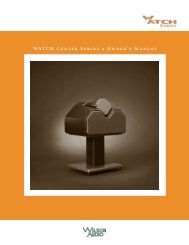
<strong>WATT</strong>/ <strong>Puppy</strong> Ow n e r ’s Ma n u a l<strong>WATT</strong> System 7:M a g n e t i c Fi e l d s - To p Vi e wv
W a t t I n t r o d u c t i o n1
W a t t I n t r o d u c t i o nAlthough they are two separate products, the <strong>Wilson</strong> <strong>Audio</strong><strong>WATT</strong> and <strong>Puppy</strong> are almost invariably used together.Thus, it seems appropriate to combine information regardingtheir use into one convenient manual.Ap p l i c at i o n sYour <strong>WATT</strong> (<strong>Wilson</strong> <strong>Audio</strong> Tiny Tot) precision loudspeaker system was designedand developed by David A. <strong>Wilson</strong> to serve as a highly accurate yet portableprofessional monitor for on-location recording work. Microphone pattern selection andplacement as well as master tape evaluations may be quickly and correctly performedusing the <strong>WATT</strong>. The extraordinary transparency, coherence, and dynamic linearity ofthe <strong>WATT</strong> also make it ideal for the sonic evaluation of audio hardware and software,including associated electronic audio equipment, such as, amplification systems, D/Aconverters, passive circuit components, signal cables, solders, and contact treatments.Its capabilities of high resolution, accurate tonal and harmonic integrity, and unsurpassedsound-stage recreation make it an ideal system for the most demanding musiclovers. In the application as a center channel for video systems the <strong>WATT</strong> (usually withA.V. <strong>Puppy</strong>), provides unrivaled dialogue intelligibility and convincing dynamics. The<strong>WATT</strong>’s size and color options allow it to be integrated harmoniously into a wide varietyof fine interior decors.De s i g n Co n s i d e r at i o n s1-1
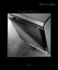
<strong>WATT</strong>/ <strong>Puppy</strong> Ow n e r ’s Ma n u a lThe <strong>WATT</strong> is designed around a massive, yet compact, enclosure utilizing proprietarypolymer materials technology. The enclosure material exhibits excellent internaldamping and a correct mechanical impedance match to the frames of the drivers.Additional mechanical tuning is provided by null point placement of lead alloy ingotblocks, bituminous surface treatment and rigid cross-bracing.The acoustical tuning ofthe low frequency system is modeled after the quasi-third order Butterworth response,(see figure 1 below), which provides linearity in the upper-bass (without the usual midbasshump) with superior transient performance. The low-frequency range of the systemis normally extended with a <strong>Wilson</strong> <strong>Audio</strong> <strong>Puppy</strong> high speed woofer. The crossovernetwork uses multiple slopes to achieve acoustical phase linearity. Minimum energy/time-storage behavior in the crossover is achieved by using only the finest audio-gradeW a t t D e s i g n C o n s i d e r a t i o n s :Thiele & Small Alignments1-2Figure 1
W a t t I n t r o d u c t i o npropylene capacitors, OFC air-core inductors, and time coherent wire. The componentsare matched to better than 0.1% tolerance. The drivers were selected because of theirfrequency response linearity, impulse stability, and most important, their intrinsic musicalquality.n o l o g yEn c l o s u r e Mat e r i a l s Te c h-The original <strong>WATT</strong> established the textbook standard for sonically inertloudspeaker enclosures. It pioneered the use of exotic cabinet materials coupled witha new benchmark for construction quality, achieving a speaker enclosure that remainsunsurpassed to this day. The System 7 employs the strategic use of a new cabinet materialthat, in conjunction with existing “X” material, serves to reduce cabinet colorationsto levels below that of the already extraordinary System 6. Distortion, noise, and audibleenclosure resonance are all substantially reduced in the System 7. This results in muchgreater clarity, resolution and tonal correctness as well as an enhanced sense of effortlessnessand ease. Dynamics are more clearly defined and delineated. Music flows froma blacker background. This material has been chosen because it provides a nearly idealblend of rigidity, mass, and internal vibration damping.THE <strong>WATT</strong> ENCLOSURE MATERIAL SHOULDBE TREATED AS THOUGH IT WERE CERAMIC!THE MATERIAL WILL NOT BEND, BUT INSTEADWILL CRACK. FOR THIS REASON USERS OF THE<strong>WATT</strong> SHOULD NOT TO ATTEMPT DISASSEMBLY OFTHE SYSTEM.1-3
<strong>WATT</strong>/ <strong>Puppy</strong> Ow n e r ’s Ma n u a lTHE <strong>WATT</strong>: A TEXTBOOK IDEALThe following is an excerpt from Martin Colloms’ book High Performance Loudspeakers, (4th Edition, pp.297-299. Pentech Press, London, 1991):“Where price is no object, costly materials and techniques can be employed to generatethe finest results. In one system example, the <strong>WATT</strong> by Dave <strong>Wilson</strong>, the enclosure benefitsfrom many techniques to achieve a remarkably inert result. The following details areall considered influential, including the small size (approximately 9 liters) which naturallyimproves strength and also results in a small enclosure surface area with reduced acousticradiation. The enclosure itself is a truncated pyramid; as a result the panels are nonrectangularand the internal surfaces anti-parallel. The latter minimizes internal standingwave modes while the former helps to disperse and moderate the usual plate resonancespresent in conventional enclosure panels. In addition the interior is lined with anechoicgrade foam supplemented by a volume filling of polyester fiber.The enclosure panels are cut from a dense, naturally inert composite - an acrylic, heavilyloaded with ceramic and a mineral powder - which may be machined like marble.Higher frequency panel modes are controlled by a highly resistive bituminous laminate onthe inner surface while the remaining fundamental resonances are handled by heavy, 20mm thick lead slabs bolted into position with elastic mountings to provide tuned, seismicdamping. Furthermore, the side panels are extended at the rear to form small triangular‘wings’. A massive alloy bar is bolted up between these wings, horizontally disposedand providing a stressed reinforcement for these largest radiating surfaces. Finally thefinished mass of approximately 25 kg provides a heavy inert foundation for the two-waydriver lineup to perform at its best. The performance attained in this enclosure design isan object lesson in the continuing importance of enclosure coloration in box speaker design.Both mechanical impulse tests and listening have shown that this quality of enclosure hasa dramatic effect in improving sound quality, particularly with transients, subjective dynamics,stereo focus and depth; as such it shows that despite considerable improvements,we still have a long way to go in the field of commercial enclosure design. However, thisperformance is achieved at high cost, approximately 15 times that of a normal enclosure1-4
W a t t I n t r o d u c t i o nof this size.”Ca r e o f t h e Finisho f Yo u r <strong>WATT</strong>sYour <strong>WATT</strong> loudspeaker enclosures are hand-painted with <strong>Wilson</strong>gloss paintand hand-polished to a high luster. While the paint seems quite dry to the touch, finalcuring and complete hardening takes place over a period of several weeks. To protectthe finish of the <strong>WATT</strong>s during final manufacture, shipment, and setup in your listeningroom, we have applied a removable layer of protective film over the finish. We recommendthat this film be left in place until the speakers are in their final location in yourlistening room. Once you have determined their final position, remove the film by peelingit off. Do not leave this film on indefinitely, as it will leave impressions on thepaint. It is important that the delicate paint finish of the <strong>WATT</strong> be dusted carefully withthe dust cloth, which has been provided. We recommend that the following procedurebe observed when dusting the speakers:• Blow off all loose dust• Using the special dust cloth as a brush, gently whiskoff any remaining loose dust• Shake out the dust cloth• Dust the finish, using linear motions in one direction parallel tothe floor. Avoid using circular or vertical motions.1-5
<strong>WATT</strong>/ <strong>Puppy</strong> Ow n e r ’s Ma n u a lBecause the paint requires a period of several weeks to fully cure, we recommendthat no cleaning fluids such as glass cleaners be used during this initial period of time.When the paint is fully cured, heavy finger prints and other minor smudges may be removedwith a glass cleaner. Always use the dust cloth. Stronger solvents are not recommendedunder any circumstances. Consult your dealer for further information if required. Periodicpolishing may be desired over the years to maintain the high luster of the finish. We recommenda non-abrasive carnuba-based wax and soft cloth.Co n n e c t i o n o f Yo u r <strong>WATT</strong> Sp e a k e r sThe very high current input terminals located on the rear of your <strong>WATT</strong> 7 loudspeakerare color coded with a small plastic plug, so that RED corresponds to positive andblack to negative, or common, or ground on the amplifier output. Be sure to connect theloudspeakers in phase with each other. We recommend the use of the very highest qualityloudspeaker cables, particularly those designed for high frequency propagation correctionand phase linearity. Beware of “zip cord” type speaker cables which will smear the soundfrom your <strong>WATT</strong>s, and limit their effective bandwidth. Also, do not use braided litz typeloudspeaker cables as they will cause an unnatural brightness to the sound, compromise1-6Figure 2
W a t t I n t r o d u c t i o nsound staging performance, and may cause instability, oscillation and damage in widebandwidth solid state amplifiers.The spade lugs of some of the high quality cables often used with the <strong>WATT</strong>/<strong>Puppy</strong> are angled to reduce pressures on the cable during installation. Avoid the instinctto push the cable’s spade lug ends all the way into the <strong>WATT</strong>/<strong>Puppy</strong>’s connectors (seefigure 2 ). Partial insertion of these angled spade lugs will actually improve the reliabilityof the connection. Flat lugs may be fully insert to connectors before tightening.Se l e c t i o n o f In t e r c h a g e a b l e Tu n i n g Po r t sThe damping factor of an amplifier is a function of the amplifier’s output impedanceinto a given load impedance. Solid state amplifiers, due to their intrinsically lowoutput impedance, tend to have a higher damping factor than vacuum tube amplifiers.Vacuum tube amplifiers typically are transformer-coupled in their output stage and thesecondary windings of the output transformer present a relatively high source impedance.This source impedance is a parameter which must be considered in the tuning ofthe air volume of the loudspeaker enclosure. An interesting theoretical considerationis that if a loudspeaker is designed around a solid state amplifier and then used with avacuum tube amplifier, it will tend to sound loose and tubby in the mid-bass regions.The <strong>WATT</strong> loudspeaker system allows you to precisely tailor the air volume tuning ofthe enclosure to the amplifier of your choice.Your <strong>WATT</strong> loudspeaker comes equipped with two sets of interchangeable tuningports. The ports connect on the back of the loudspeaker system and are affixedwith three (3) button-head stainless steel screws. An allen key is provided which canbe used to remove these screws to facilitate exchange of the ports. Typically, <strong>WATT</strong>sare shipped with the “D.F. 100-400” ports installed. This range encompasses the majorityof high performance solid state amplifier types. Most vacuum tube amplifiers havedamping factors of from 20 to 80, and we recommend the port which is labeled “D.F.20-80.”T E C H N I C A L N O T E1-7
<strong>WATT</strong>/ <strong>Puppy</strong> Ow n e r ’s Ma n u a lMo u n t i n g He i g h t sThe acoustical center of the <strong>WATT</strong> speaker system is at a point near the top edge of thewoofer, which we are referring to as “Point A.” The system’s phase coherence, as well asits upper midrange and high frequency amplitude response, are most linear when measuredon axis with Point A. Placing the speakers above the listener’s head displaces the alignmentof the woofers’ output in front of the tweeter. Such placement is possible, but ideally, the<strong>WATT</strong> should be angled down, toward the listener. Contact your <strong>Wilson</strong> <strong>Audio</strong> dealer formore information. The more common placement of the <strong>WATT</strong> is at or below ear level.The effect of different mounting heights on the response of the <strong>WATT</strong>s is examined in figures3 through 6.<strong>WATT</strong>- o n Fl o o rIn the first example (figure 3), we see the <strong>WATT</strong> placed on the floor. In this configurationthe <strong>WATT</strong>s low frequency response will be quite linear down to its lower band passlimit. Midrange to upper bass response is particularly smooth. If the floor is carpeted, thehigh frequency response will be somewhat depressed in amplitude, but clean. The soundstagingperformance of the system will be hampered by comb-filter effects in the uppermidrange and lower treble, which will also create a somewhat hollow-sounding coloration.Some listeners will prefer the mellow over-all tonal balance of this configuration, and indeed,several <strong>WATT</strong> systems incorporate essentially this placement with the <strong>WATT</strong>s mountedin consoles.1-8
W a t t I n t r o d u c t i o nFigure 31-9
<strong>WATT</strong>/ <strong>Puppy</strong> Ow n e r ’s Ma n u a l<strong>WATT</strong>- 18 In c h Sta n dIn the second illustration (figure 4), we see the <strong>WATT</strong> elevated to 18 inches abovethe floor on an open frame stand. There is some loss of low frequency response because ofthe reduction in 2 pi steradian support of woofer output. The acoustical center of the <strong>WATT</strong>is now closer to ear level, thus sound staging will be improved, and the high frequencyresponse will be more linear than in the first example. Resolution of low level detail is im-1-10Figure 4
W a t t I n t r o d u c t i o n<strong>WATT</strong>-24 In c h Sta n dThe third illustration (figure 5), shows the effects of the speaker being raised an additional6 inches off the floor. Here the sound staging properties will be excellent as will highfrequency linearity and overall lucidity of detail. There will, however, be a noticeable lossin bass and lower midrange response due to the lack of 2 pi steradian support of the directoutput of the woofer. Generally, as the <strong>WATT</strong> is raised up off the floor, the sound becomes“lighter” in balance as the speaker’s height is increased. The recommended range of mountingheights is from 18 inches to 28 inches.Figure 51-11
<strong>WATT</strong>/ <strong>Puppy</strong> Ow n e r ’s Ma n u a l<strong>WATT</strong> o n Pu p p yIn the fourth example (figure 6), we see the effects of mounting the <strong>WATT</strong> on the<strong>Puppy</strong>. This base provides the effect of 2 pi steradian support, and therefore results in afuller, warmer, more rounded sound - even if the <strong>Puppy</strong> were not electronically connected.With the <strong>Puppy</strong> connected we see and extension of the base and a smoother, more even midrange.1-12Figure 6
for best low frequency transient response andcleanest mid-range, Always use spiked feet on the stand- between the stand and the floor, and optionally betweenthe stand and the speaker. If the stand has hollowlegs, fill them with sand to eliminate upper midrangeringing in the stand.1-13
P u p p yIn t r o d u c t i o n2
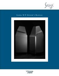
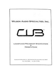
P u p p y I n t r o d u c t i o nP u p p y 7:Co m p o n e n t s a n d Di m e n s i o n sDecouplingPlate18 1 / 2”Phase DelayCorrectionReference<strong>WATT</strong> SpikePlacement RampTwo 8 inchWoofers26 1 / 2”12 1 / 4”2-1
<strong>WATT</strong>/ <strong>Puppy</strong> Ow n e r ’s Ma n u a lCa b i n e t De s i g nAt the core of each <strong>Wilson</strong> <strong>Audio</strong> loudspeaker design is the knowledge that toachieve the best performance in the world, you must start with the best materials. Here arejust two of the in-depth engineering solutions that enhance the <strong>Puppy</strong> enclosure.Mat e r i a lThe <strong>Puppy</strong> cabinet is constructed from a high-density, resin based composite. Thiscomposite meets and exceeds the highest of ANSI test standards for its use, while offeringvery tight tolerances, high hardness, uniform density, and dimensional stability. The highhardness of this composite not only offers excellent acoustical properties, but it also providesan ideal surface for painting. Thus, your high gloss finish will be as durable as it is beautiful.Ad h e s i v eWhat’s in an adhesive? Everything. This often over looked element is crucial to theproper performance of a loudspeaker. Correct modulus of elasticity, coefficient thermal expansionand natural frequency response are just a few of the important elements.A highly cross-linked, thermo-set adhesive is used for the construction of the enclosure.It was also chosen for its excellent bond strength, solvent resistance, hardness andoptimum vibrational characteristics.De p t h o fDe s i g nThe combination of the best in composite materials and adhesive technology, providedto us by the leaders in their industry, allow us to design an enclosure with unmatchedperformance. The <strong>Puppy</strong> cabinet has been designed to eliminate vibration and cabinet signature,while maintaining an internal acoustical integrity that is, quite simply, the best.All of these structural aspects combine to allow <strong>Wilson</strong> <strong>Audio</strong> to deliver a productthat maintains the strictest structural tolerances, durability and reliability. This also meansthat you will have consistent, repeatable performance, unaffected by the climatic conditions,2-2
P u p p y I n t r o d u c t i o nOr i g i n a l De s i g n Co n s i d e r at i o n sThe original <strong>Puppy</strong> high speed woofer was introduced in 1988, two years afterthe first <strong>WATT</strong>, series I. Prior to the <strong>Puppy</strong>, users of the <strong>WATT</strong> who desired more lowfrequency extension, would add various subwoofers from other manufacturers. Theresults were unpredictable and often compromised overall musical performance. It becameclear to Mr. <strong>Wilson</strong> that none of these subwoofers provided the speed necessary toblend seamlessly with the lightning-quick <strong>WATT</strong>.Thus, in the initial design phase of the <strong>Puppy</strong>, <strong>Wilson</strong> concluded that what wasneeded was a highly articulate, low distortion, non-resonant, compact high-speed wooferwith robust power handling, high sensitivity and excellent reliability. In every series ofpuppy, two very high quality low-frequency drivers are driven in parallel in a rigidlycross-braced, tuned enclosure to quickly dampen spurious resonances in the structure.The crossover network in the base of the <strong>Puppy</strong> is always composed of the finest audiograde components, held to tolerances better than 0.1%.Pu p p y 7.0The System 7 <strong>Puppy</strong> employs a new woofer driver. Bass performance,especially in the areas of transient speed and frequency linearity, is notably improvedover any previous generation <strong>Puppy</strong>. Bass extension into the bottomoctave is also slightly enhanced. The <strong>Puppy</strong> 7’s bass performance is more consistentin a wider variety of rooms and environments.2-3
<strong>WATT</strong>/ <strong>Puppy</strong> Ow n e r ’s Ma n u a lCa r e o f t h e Finish o f Yo u r Pu p p yThe standard finish of your <strong>Puppy</strong> is <strong>Wilson</strong>gloss TM paint. Painted <strong>Puppy</strong>s should betreated as described in the section on Care of the Finish of Your <strong>WATT</strong>s (page 1-5). Do not,under any circumstances, use organic solvents.T E C H N I C A L ‐ N O T EIf the user wishes to test the polarity of the <strong>Puppy</strong> 7 with a battery, the plus (+)terminal of the battery is connected to the red (+) input terminal of the <strong>Puppy</strong>and the negative (-) terminal of the battery is connected to the BLACK (-) terminalof the <strong>Puppy</strong>. The results of this test will show the <strong>Puppy</strong> woofers to moveoutward. This is the correct driver movement in response to a D.C. signal.2-4
P u p p y I n t r o d u c t i o nThis page intentionally left blank2-5
I n Y o u r R o o m3
Y o u r R o o mI nRo o m Re f l e c t i o n sFigure 7 (below) illustrates the 3 most commonly encountered room reflection problems,slap-echo, standing waves, and comb filter effects.Sl a p-Ec h oProbably the most obnoxious form of reflection is the “slap echo.” In slap echo,primarily mid-range and high frequency sounds reflect off of two parallel hard surfaces.The sound literally reverberates back and forth until it is finally dissipated over time. Youcan test for slap echo in any room by clapping your hands sharply in the middle of the roomand listening for the characteristic sound of the echo in the mid-range. Slap echo destroysthe sound quality of a stereo system primarily in two ways:• Adding harshness to the upper mid-range and treble throughenergy time storage• Destroying the delicate phase relationships which help to establishsoundspace and image localization clues.3 Co m m o n ly En c o u n t e r e d Re f l e c t i o n Pr o b l e m sFigure 73-1
<strong>WATT</strong>/ <strong>Puppy</strong> Ow n e r ’s Ma n u a lNon-parallel walls do not support slap echo, but rather allow the sound to diffuse.Slap echo is a common acoustical problem in the typical domestic listening room, becausemost of these rooms have walls of a hard, reflective nature, usually being only occasionallyinterrupted by curtains or drapes. Slap echo can be controlled entirely by theapplication of absorptive materials to hard surfaces, such as:• Sonex• Airduct board• Cork panels• Large ceiling to floor drapes• Carpeting to wall surfacesIn many domestic listening environments, heavy stuffed furnishings are the primarystructural control to slap echo. Unfortunately, their effectiveness is not predictable. Diffusersare sometimes also used to very good subjective effect, particularly in quite largerooms. Sound absorbent materials such as described above will alter the tonal characteristicof the room by making it sound “deader,”much heavier in bass tonal balance,less “bright and alive” and “quieter.” These changes usually make the room more pleasantfor conversation, but sometimes render it too dull in the high frequencies to be musicallyinvolving. Diffusers, on the other hand, tend to not change the high frequencytonal balance characteristic of the room, but make the sound more “open”. A combinationof absorbtive and diffusive treatments is usually the best approach.Sta n d i n g Wav e sAnother type of reflection phenomenon is “standing waves”. Standing wavescause the unnatural boosting of certain frequencies, typically in the bass, at certain discreetlocations in the room. A room generating severe standing waves will tend to makea loudspeaker sound one way when placed in one location and entirely different whenplaced in another. The effects of standing waves on a loudspeaker’s performance areprimarily, as follows:• Tonal balance-Bass too heavy• Low-level detail- Masked by long reveration time LF standingwaves3-2
Y o u r R o o mI n• Sound staging- LF component of image shiftedStanding waves are more difficult to correct than slap echo because they tendto occur at lower frequencies, whose wave lengths are long enough to be ineffectivelycontrolled by absorbent materials such as Sonex. Moving speakers about slightly in theroom is, for most people, their only control over standing waves. Sometimes a changeof placement of as little as one inche can dramatically alter the tonal balance of a systembecause of standing wave problems. Fortunately, minor low frequency standing wavesare sometimes well controlled by positioning ASC tube traps in the corners of the room.Very serious low frequency accentuation usually requires a custom-designed bass trapsystem.Low frequency standing waves can be particularly troublesome in rooms constructedof concrete or brick. These materials trap the bass in the room, unless it is allowedto leak out of the room, through large window and door areas.In general, placement of the speaker in a corner will excite the maximal numberof standing waves in a room, and is to be avoided for most direct radiator, full rangeloudspeaker systems. Some benefit is achieved by placing the stereo pair of loudspeakersslightly asymmetrically in the listening room so that the standing waves caused bythe distance between one speaker and its adjacent walls and floors are not the same asthe standing wave frequencies excited by the dimensions in the other channel.Comb Filter EffectA special type of standing wave, noticeable primarily in the mid-range and lowerhigher frequencies is the so-called “comb filter effect”.Acoustical comb filtering occurs when sound from a single source, such as aloudspeaker, is directed toward a microphone or listener at a distance. The first sound toreach the microphone will be the direct sound, followed by delayed reflected sound. Atcertain frequencies cancellation occurs, because the reflected sound lags in phase relativeto the direct sound. This cancellation is most apparent where the two are 180 degreesout of phase. There is augmentation at other frequencies where the direct and thereflected sounds arrive in phase. Because it is a function of wave length, the comb filtereffect will notch out portions of the audio spectrum at regular octave-spaced intervals.3-3
<strong>WATT</strong>/ <strong>Puppy</strong> Ow n e r ’s Ma n u a lThe subjective effect of comb filter effects, (such as is shown in figure 8) is as follows:• Added roughness to the sound• Reduction of harmonic richness• Smearing of lateral sound stage image focus and placementComb filter effects are usually caused by side wall reflections. They are best controlled byvery careful speaker placement and by the placement of Sonex or air duct panels applied tothat part of the wall where the reflection occurs.Re f l e c t i v e Ac o u s t i c a l Co m b Fi lt e r Ef f e c t3-4Figure 8
Y o u r R o o mI nRe s o n a n c e sResonances in listening rooms are generally caused by two sources:St r u c t u r a l r e s o n a n c e s• The structures within the listening room• The volume of the air itself in the listening roomStructural resonances are familiar to most people as buzzes and rattles, but this typeof resonance usually only occurs at extremely high volume levels, and is usually maskedby the music. In many wood frame rooms, the most common type of structural resonanceproblem is “booming” of walls and floors. You can test for these very easily by tappingthe wall with the heel of your hand or stomping on the floor. If it is a wooden floor, this isdone to detect the primary spectral center of the resonance. To give you an idea of what theperfect wall would sound like, imagine rapping your hand against the side of a mountain.Structural wall resonances generally occur in the low to mid-bass frequencies and add tonalbalance fullness to any system played in that room. They too are more prominent at louderlevels, but their contribution to the sound of the speaker is more progressive. Rattlingwindows, picture frames, lamp shades, etc. can generally be silenced with small pieces ofcaulk or with blocks of felt. Short of actually adding additional layers of sheet rock or bookshelves, to flimsy walls, however, there is little that can be done to eliminate wall resonances.Air Vo l u m e Re s o n a c eThe volume of air in a room will also resonate at a frequency determined by the sizeof the room. Larger rooms will resonate at a lower frequency than will smaller rooms. Airvolume resonances, wall panel resonances, and low frequency standing waves, together,combine to form a low frequency coloration in the sound. At its worst, it is a grossly exaggeratedfullness, which tends to obscure detail and distort the natural tonal balance of thespeaker system. Occasionally, however, there is just enough resonance to give a little addedwarmth to the sound... an addition some listeners prefer. Tube traps manufactured by theASC corporation have been found to be effective in reducing some of these low frequencyroom colorations. While custom designed and constructed bass traps, such as perforatedHelmholtz resonators, provide the greatest degree of low frequency control.
<strong>WATT</strong>/ <strong>Puppy</strong> Ow n e r ’s Ma n u a lRo o m Sh a p e sThere are three basic shapes for most rooms: square, rectangular, and L-shaped (seeFigure 9). A perfectly square room is the most difficult room in which to set up speakers because,by virtue of its shape, square rooms are the perfect medium for building and sustainingstanding waves. Standing waves are pressure waves created by the integration of sound andopposing, parallel walls which accentuate particular frequencies. They heavily influence themusic played by loudspeakers, greatly diminishing the quality of the listening experience.Long, narrow rectangular rooms also pose their own special acoustical problems forspeaker setup. They have the ability to set up several standing wave nodes, which will havedifferent frequency exaggerations depending on where you are sitting. Additionally, theselong rooms are often quite lean in the bass near the center of the room. Rectangular roomsare still preferred to square rooms because by having two sets of dissimilar length walls,standing waves are not as strongly reinforced and will dissipate more quickly than in a squareroom. In these rooms the preferred speaker position for spatial placement and midrange resolutionwould be on the longer walls. Bass response would be reinforced, albeit not predictably,by speaker placement on the short walls.In many cases L-shaped rooms offer the best environment for speaker setup. Ideallyspeakers should be set up along the primary (longest) leg of the room. They should fire fromthe end of the leg (short wall) toward the bend, or they should be along the longest wall, withthe speaker furthest to the bend being inside of the bend. In this way both speakers are firingthe same distance to the back wall. The asymmetry of the walls in L-shaped rooms resiststhe buildup of standing waves.3-6
Y o u r R o o mI nCo m m o n Ro o m Sh a p e s:Op t im u m Sp e a k e r Pl a c e m e n t sFigure 93-7
<strong>WATT</strong>/ <strong>Puppy</strong> Ow n e r ’s Ma n u a lEf f e c t s o f Ro o m Pl a c e m e n tThe <strong>WATT</strong>/ <strong>Puppy</strong> System 7s were designed to be aimed at the listener, whichmeans that they will be toed-in prominently rather than facing straight ahead. The illustrationsto follow will give examples of many common scenarios to assist you in the setup procedure.The effect of room placement of the performance of the <strong>WATT</strong> is illustrated infigures 10, 11, and 12.Co r n e r v s. In r o o m Pl a c e m e n t (n o t o e)Figure 10 examples 1A and 1B and table 4 compare the performance of cornersituated <strong>WATT</strong>s vs <strong>WATT</strong>s which are placed out in the room away from walls, butwhich are not toed-in. Placement of any direct full-range radiator loudspeaker in thecorner results in numerous performance compromises. In one respect, however, cornerplacement of the speaker excels, and that is in low frequency augmentation. Lookingat the tonal balance characteristic of the corner situated <strong>WATT</strong>s we can see an elevatedlower midrange through mid bass region, the expected effect of corner loading, coupledwith a gradual roll-off of the upper octaves, the result of any sound absorbing materialson adjacent walls, and the off-axis listening position.The corner placed speakers are also significantly further away from the listenerthan the speakers in example 1B. By its very nature, sound, when traveling through air,loses low-level detail with distance. Ideally, therefore, the listener should sit as close tothe speakers as is comfortable. Moving the speakers out into the room at least three feetfrom the rear wall, and at least two feet from the side walls, provides a fairly dramaticlevel of improvement of sound staging performance and overall mid and upper octavebalance. But still the example shows the speakers not toed in. The <strong>WATT</strong>s are designedfor maximum phase coherence and pulse replication accuracy when they are aimed directlyat the listener or microphone.3-8
Y o u r R o o mI nFigure 10 3-9
<strong>WATT</strong>/ <strong>Puppy</strong> Ow n e r ’s Ma n u a l<strong>WATT</strong>- In r o o m Pl a c e m e n t (w i t h t o e)Figure 11 shows the effect of toeing in the <strong>WATT</strong>s. The speakers in example 2are in the same general room location as the speakers in 1B, but are toed in. When the<strong>WATT</strong>s are correctly toed in, the listener, when seated in the listening position, will justbarely see the surface of the inner side panels of the <strong>WATT</strong>s. We can see that toeingin the speakers provides dramatic improvements in resolution of low level detail in themidrange as well as dramatic improvements in sound staging performance. It should benoticed that in the tonal balance curve in the table reveals irregularities in response inthe upper bass through lower midrange. These are caused by standing waves and adjacentwall comb filter effects. The performance indicated in the table is very promising,and yet it is not really representative of the best performance of which the <strong>WATT</strong> is capable.Any speaker will benefit from appropriate acoustical room treatment.Figure 113-10
Y o u r R o o mI n<strong>WATT</strong>- In r o o m Pl a c e m e n t, w i t h t o e, a n d Ac o u s t i c a l Tr e at m e n tLet us now go to figure 12, to see the benefits in performance which can be achievedby modest acoustical treatment of the room. With the speakers in the same location as infigure 11, we note the addition of tube traps in the corners of the listening room, as well asfoam or Sonex panels placed between and behind the speakers, against the back wall, aswell as along the wall behind the listener and over to the side next to the listener. The tubetraps can be seen to smooth out the performance of the upper bass and lower midrange,while at the same time not compromising low frequency extension. Slap echo is controlledby the sound absorbing panel on the wall behind the speakers in the center of the soundstage and by the two panels on the back wall behind the listener. These two room treatments,namely tube traps and judicious placement of sound absorptive panels, can elevatethe sonic performance of virtually any speaker system in a typical domestic listening room.Should the listening position be as far from the speakers as possible, even up againsta back wall? Figure 12, position B shows the effect of being seated near a back wall, somedistance from the speaker. We can see a dramatic increase in upper bass and mid bass outputof the system, actually due to standing wave reinforcement near the back wall, as wellas the expected high frequency roll off resulting in the longer air path of the sound to thelistener.It should be noted that, in comparison to other speaker systems, even this compromisedlevel of sound staging performance and resolution of low level detail still representsvery good performance indeed.3-11
<strong>WATT</strong>/ <strong>Puppy</strong> Ow n e r ’s Ma n u a l3-12Figure 12
Y o u r R o o mI nSp e a k e r Pl a c e m e n t v s. Li s t e n i n g Po s i t i o nThe location of your listening position is as important as the careful setup placementof your <strong>WATT</strong>/<strong>Puppy</strong> System 7 speakers in your room. The listening position should ideallybe no more than 1.1 to 1.25 times the distance between the tweeters on each speaker. Therefore,in a long rectangular room of 12’ x 18’, if the speaker tweeters are going to be 9’ apart,you should be sitting 9’11’’ to 11’3’’ from the speaker. This would be about halfway downthe long axis of the room. Experiment carefully for best low frequency response.Some people place the speakers on one end and sit at the other end of the room.Needless to say, this will not yield the finest sound. Carefully consider your listening positionfor optimal performance. Our experience has shown that any listening position which placesyour head closer than 14” to a room boundary will diminish the sonic results of your listening.Ch o o s i n g a Li s t e n i n g Po s i t i o nDecide where you want your favorite listening position to be. Please remember thatyour <strong>WATT</strong>/<strong>Puppy</strong>s can fill almost any room with the most beautiful sound. However, forthe time aligning advantage, we want to ensure that you get all the benefits possible with thegruop delay adjustment features that are built into this design. For this purpose we ask you toconsider the following questions:What is the main purpose of your <strong>WATT</strong>/<strong>Puppy</strong>s? Is it for a listening room dedicatedto 2-channel audio? If yes, you should choose your position carefully to yield the finestsound. <strong>Wilson</strong> <strong>Audio</strong> uses a formula: The distance between the tweeters of the two channeltimes 1.2 equals the distance you should sit from each loudspeaker.For instance, if you measure the distance between the center of the left channeltweeter to the corresponding right channel tweeter and it is equal to 10 feet, multiply it by1.2. This means that you should sit approximately12 feet from each <strong>WATT</strong>/<strong>Puppy</strong> channel.Are your <strong>WATT</strong>/<strong>Puppy</strong>s dedicated for a home theater?Are you going to sit on a couch, or will there be multiple rows of chairs?If it is a couch, you should center the loudspeakers on the center position of thecouch.Multiple rows of chairs - In this case you should calculate the 1.2 times equation onyour second row of seating. Now more people will enjoy the power of your <strong>WATT</strong>/<strong>Puppy</strong>s.Do you still want to listen to 2 channel music at its highest quality? In this way youcan enjoy optimized sound from that second seat.3-13
<strong>WATT</strong>/ <strong>Puppy</strong> Ow n e r ’s Ma n u a lSp e a k e r Or i e n tat i o nSpeaker placement and orientation are two of the most important considerations inobtaining superior sound. The first thing you need to do is minimize the influence of the sidewalls on the sound of your system. Speakers placed too close to the side walls will sufferfrom a strong primary reflection. This can cause out-of-phase cancellations, or comb filtering,which will cancel some frequencies and change the tonal balance of the music. A goodplace to start is with the speakers about 18” from each wall and, if you need to move themrelative to the side wall, move them away from the wall, not closer.A very important aspect of speaker placement is how far to place the speakers fromthe wall behind them. The closer to the back wall the more pronounced the low bass energyand centering of the image will be. However, this comes at a definite reduction in stage sizeand bloom, as well as a deterioration of upper bass quality. You must find the proper balanceof these two factors, but remember, if you are partial to bass response or air and bloom, donot overcompensate your adjustments to maximize their effects. Overbalanced systems aresometimes pleasing in the short term, but long term satisfaction is always achieved throughproper balance.The <strong>WATT</strong>/<strong>Puppy</strong> System 7 is designed for maximum phase coherence and pulsereplication accuracy when they are aimed directly at the listener or microphone. Thus, your<strong>WATT</strong>/<strong>Puppy</strong>s should be “toed in.” In other words, the listener, when seated in the listeningposition, should just barely see the surface of the inner side of the <strong>WATT</strong>/<strong>Puppy</strong>. Toeing inthe speakers provides dramatic improvements in resolution of low level detail in the midrange,as well as dramatic improvements in sound staging performance.Su m m a r yIn summary, it is clear that, for optimal tonal balance accuracy, resolution of low leveldetail and sound staging performance, the <strong>WATT</strong> should be positioned at or slightly belowear level of the listener. The <strong>Puppy</strong> is the ideal compliment to the <strong>WATT</strong>, in that it establishesa correct height, is non-resonant, its high-pass crossover protects the <strong>WATT</strong> woofer,and response is extended to below 25Hz (see Figure 13 for <strong>WATT</strong>/<strong>Puppy</strong> response).3-14
Y o u r R o o mI nIdeally, the speakers should not be positioned too far from the listener, if maximum resolutionof low level detail is required (near-field monitoring). If possible, the speakersshould be positioned out into the room, slightly asymmetrically away from side and rearwalls. The speakers should be toed-in toward the listener, preferably so that the listenerat his seated position can barely see the surface of the inner side panel of the <strong>WATT</strong> ashe faces the speaker. It is recommended that a distance of 2-3 feet, and possibly more,be maintained between the <strong>WATT</strong> and the rear walls and a distance of at least 1 1/2 feetbe maintained between the front panel of the <strong>WATT</strong> and reflective side walls. Use ofsound absorbent materials may reduce the space requirement somewhat. Experiment foreach room.By following the guidelines in this manual and your own common judgement,your new <strong>WATT</strong>/<strong>Puppy</strong> speakers will provide you with a lifetime of pure music reproduction.Figure 133-15
p y S y s t e m 6.0 S e t u p<strong>WATT</strong> / P u p -4
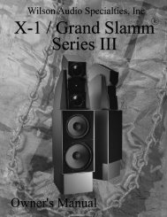
p y S y s t e m 6.0 S e t u p<strong>WATT</strong> / P u p -Note: Before setting up the Watt/<strong>Puppy</strong> System 7 study carefully the previous sectionon room acoustics. It provides valuable information on determing the ideal room location foryour speakers.Pr e pa r at i o nYou will need the following items:• Supplied hardware kit• Tape measure• Geometric timing charts (Appendix A)• Known listening positionTake a moment to familiarize yourself with the top of the <strong>Puppy</strong>. It contains informationthat will be needed during the setup (see Figure 14 below).Painted InnerEdgePhase DelayCorrection TableWatt SpikePlacementRampFigure 144-1
<strong>WATT</strong>/ <strong>Puppy</strong> Ow n e r ’s Ma n u a lSe t u p• Place the <strong>Puppy</strong> enclosures into the selected room location (as determinedby section 3)• Determine your listening position• Measure the listening distance and ear height (see example on <strong>Puppy</strong> top)• Using the Phase Delay Correction Table select the required AlignmentSpike• Install the <strong>WATT</strong>s front spike until snug• Install the Alignment Spike until snugNote: If using any spacers with your <strong>Puppy</strong> Paws refer to Appendix A for correct alignment table<strong>WATT</strong> Front SpikesHand tighten until snug4-2<strong>WATT</strong> Alignment SpikeLength determined by Phase DelayCorrection TableFigure 15
p y S y s t e m 6.0 S e t u p<strong>WATT</strong> / P u p -• Carefully, place <strong>WATT</strong> onto spike placement ramp on top of the <strong>Puppy</strong>about 3 inches from the front. Be careful not to damage the lower edges ofthe Watt or <strong>Puppy</strong> top• Grasping the handle and top of <strong>WATT</strong>, slide the <strong>WATT</strong> forward untilthe spikes just slide off the ramp (see Figure 16 below)Place Watt hereFigure 164-3
<strong>WATT</strong>/ <strong>Puppy</strong> Ow n e r ’s Ma n u a l• Carefully, lower the rear of the <strong>WATT</strong> onto the decoupling plate• Adjust the position of the <strong>WATT</strong> so it is centered on the <strong>Puppy</strong>• Remove the protective film. To remove, just start at the edge and peel itoff.AlignmentSpikeMain input fromamplifierFigure 174-4
p y S y s t e m 6.0 S e t u p<strong>WATT</strong> / P u p -Pu p p y Ta i l Co n n e c t i o nThe correct connection of the <strong>Puppy</strong> Tail in the <strong>WATT</strong>/<strong>Puppy</strong> system 7 is:• Connect the other RED lug at the load end of the tail to the REDterminal on the <strong>WATT</strong>.• Connect the other BLACK lug at the load end of the tail to the BLACKterminal on the <strong>WATT</strong>.Note: Please resist the temptation to invert the polarity of the <strong>Puppy</strong> Tail in the<strong>WATT</strong>/<strong>Puppy</strong> System 7. Such an inversion will produce entertaining ambient effects,but destroys the linearity and harmonic structure of the system.4-5
<strong>WATT</strong>/ <strong>Puppy</strong> Ow n e r ’s Ma n u a lPu p p y Paw sIncluded with your <strong>WATT</strong>/<strong>Puppy</strong> System 7 are two sets of <strong>Puppy</strong> Paws, whichprovide acoustical isolation as well as optimal height placement for your speakers.There are three ways of assembling the paws (without spacers, or with one or two spacers),and your choice will depend on your listening room and personal tastes. <strong>Wilson</strong>generally recommends no spacers, for simplicity and rigidity. However, the addition ofspacers changes the driver-to-floor dimension, and can sometimes be used to reduce anobjectionable upper-bass/lower mid-range standing wave.As s e m b ly:1. Insert either the short or the long threaded bolt, depending on the desired height (seefigure 18 next page) as far as it will go into the hole in the bottom of the <strong>Puppy</strong>.Make sure the Allen key end is accessable.2. If desired, place the corresponding number of spacer discs over the bolt.3. Screw the acoustical diode onto the bolt until it butts up against the spacers or <strong>Puppy</strong>bottom.4. Screw the spike (with nut) all the way in until it just touches the bolt. Do not tightenthe nut at this time.5. Repeat steps 1 through 4 with the other three paws.6. To provide the proper mechanical coupling between the <strong>Puppy</strong> Paws and the floor,make sure that the <strong>Puppy</strong> is level by unscrewing individual spikes as needed untileven contact is achieved by all four Paws. A bubble level is often helpful in thisprocedure.7. Once all adjustments have been made, tighten the nut on the spike to the diode withthe 9/16” wrench provided. DO NOT OVERTIGHTEN! “Snug” is tight enough.4-6
p y S y s t e m 6.0 S e t u p<strong>WATT</strong> / P u p -P u p p y Pa w sAs s e m b ly Di a g r a mOption 1(0-1 Spacers)Allen Key End ofSetscrewLock NutDiode1.5 inch SetscrewOptionalSpacerSpikeOption 2(2 Spacers)2 inchSetscrew2 SpacersFigure 184-7
<strong>WATT</strong> / P u p p y S y s t e m7 T a b l e s5
5-1
5-2