Owner's Manual - Wenger Corporation
Owner's Manual - Wenger Corporation
Owner's Manual - Wenger Corporation

Create successful ePaper yourself
Turn your PDF publications into a flip-book with our unique Google optimized e-Paper software.
IMPORTANT USER INFORMATIONGENERALCopyright © 2012 by <strong>Wenger</strong> <strong>Corporation</strong>All rights reserved. No part of the contents of this manual may be reproduced, copied, or transmitted inany form or by any means including graphic, electronic, or mechanical methods or photocopying,recording, or information storage and retrieval systems without the written permission of the publisher,unless it is for the purchaser's personal use.Printed and bound in the United States of America.The information in this manual is subject to change without notice and does not represent a commitmenton the part of <strong>Wenger</strong> <strong>Corporation</strong>. <strong>Wenger</strong> <strong>Corporation</strong> does not assume any responsibility for anyerrors that may appear in this manual.In no event will <strong>Wenger</strong> <strong>Corporation</strong> be liable for technical or editorial omissions made herein, nor fordirect, indirect, special, incidental, or consequential damages resulting from the use or defect of thismanual.The information in this document is not intended to cover all possible conditions and situations that mightoccur. The end user must exercise caution and common sense when assembling or installing <strong>Wenger</strong><strong>Corporation</strong> products. If any questions or problems arise, call <strong>Wenger</strong> <strong>Corporation</strong> at 1-800-733-0393.MANUFACTURERThe flipFORMS are manufactured by:<strong>Wenger</strong> <strong>Corporation</strong>555 Park DriveOwatonna, MN 550601-507-455-4100 • 1-800-733-0393 www.wengercorp.comINTENDED USE• This product is intended for indoor use in normal ambient temperature and humidity conditions — itmust not be exposed to prolonged outside weather conditions.• This product is intended to be assembled only as described in these instructions.WARRANTYThis product guaranteed free of defects in materials and workmanship for five full years from date ofshipment. A full warranty statement is available upon request.2
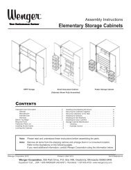
BEFORE YOU BEGIN• Read the complete assembly procedure before you begin.• Open both large cartons, and compare the parts to the “Replacement Parts List” listed below.• Fasteners and loose parts are packed in the Hardware Pack.• Screws should be threaded into plastic parts with a #2 phillips screwdriver or battery powered screwdriver If using a power screw driver, set on lowest speed setting. Tighten to approx. 1 ⁄8" from tightand finish tighening with hand screw driver. Tighten the screws just enough to bring the partstogether and stop. Don’t over tighten! Additional tightening will not increase holding power andmay actually reduce holding power of the screw.Note: Due to variability in the manufacturing process, molded screw start points at some locations maynot be fully formed. It may be necessary to drill a tiny pilot hole using a 1 ⁄8" diameter drill bit(provided). Often the screw will cut its own pilot hole if sufficient pressure is applied to thescrewdriver.! CAUTIONMake sure that anyoneworking on the flipFORMShas read and understandsthis manual.REQUIRED TOOLS! CAUTIONIt is unsafe for only oneperson to assemble theflipFORMS.! CAUTIONEye protection is requiredwhen assembling theflipFORMS.The following tools must be available to assemble the flipFORMS:• Phillips Screwdriver or battery powered “slow” speed screw driver.• Rubber Mallet• 1⁄8" diameter Drill Bit (provided)FASTENER LIST• Phillips pan-head self-tapping screw, #10 x 1 1 ⁄2"• Phillips pan-head self-tapping screw, #10 x 2"PARTS LISTABCD E F(with wheels)3
PARTS LIST (CONTINUED)FGH(without wheels)JJ(with wheels)(without wheels)KLMNOPPART QTY DESCRIPTION PART QTY DESCRIPTIONA 4 STEP TOP WITH NOTCH J 1 10" (25.4 CM) SUPPORT WITH WHEELSB 3 STEP TOP WITHOUT NOTCH J 1 10" (25.4 CM) SUPPORT WITHOUT WHEELSC 1 BASE SIDE LEFT HAND K 1 4" (10 CM) STEP END LEFT HANDD 1 BASE SIDE RIGHT HAND L 1 4" (10 CM) STEP END RIGHT HANDE 2 7" (18 CM) BASE SUPPORT M 1 2" (5 CM) SUPPORT WITH DOVETAILS ON ENDSF 1 11" (28 CM) BASE SUPPORT WITH WHEELS N 1 2" (5 CM) SUPPORT WITHOUT DOVETAILS ON ENDSF 3 11" (28 CM) BASE SUPPORT WITHOUT WHEELS O 8 HINGE COVERG 1 12"(30.5 CM) STEP END LEFT HAND P 4 HINGE LINKH 1 12" (30.5 CM) STEP END RIGHT HAND4
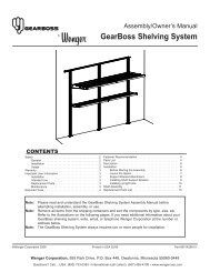
ASSEMBLY1. Base Assemblya. Orient the base parts similar to figure 1 with the parts laying flat on the floor.b. Assemble all cross supports to one side panel as follows:1. Position part E dovetail into side panel part C slot labeled E with the flipFORM logo out.2. Lift the back end of the side panel to position second part E in the next slot. The one part Fsupport with the wheels must face the back of the base.3. Position the three part F supports without wheels in the next three slots labeled part F.4. Position the part F support with wheels in the back labeled part F.5. Go to the other side and slide part D over the dovetail keys.6. Push down on the side panels until the top surfaces are flush with the six supports.Tighten the screws only enough to bring the parts together and stop.2" (5cm)screwPart Cleft sideF EEPart Bun-notched top1 1 ⁄2" (4 cm )screwFFFPart EPart Anotched topsF2" (5 cm)screwPart F11" (28 cm)with wheelsPart Dright sidefigure 1c. Assemble two part “A” notched top panels to the upper level of the base with notches at theouter corners as follows:1. Lay the top panels over the dovetail keys on the supports and slide to the side to center.A rubber mallet may be needed to drive the top panel to center. After first screw is in placetop can be moved over slightly with mallet to center second hole.2. Assemble the un-notched top panel part B to the lower level of the base.3. Lock the tops down with one 1 1 ⁄2" (4 cm) screw at each end using a hand screwdriver.4. Using a 2" (5 cm) screw, secure each side panel to the front part E support.Tighten the screws only enough to bring the parts together and stop.5
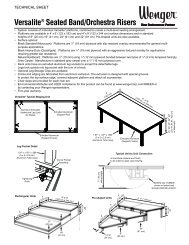
ASSEMBLY (CONTINUED)2. 12" Step Assembly:a. Orient the 12" (30.5 cm) step parts as shown in figure 2.1. Lay the un-notched top panel part B face down on a flat surface with dovetail slots asshown.2. Position the part J support with wheels down and toward you, and slide to the right to lockin.3. Slide the end panel parts G and H down over the dovetail keys with hinge pockets towardyou.4 Put a 2" ( 5 cm ) screw in the hole in each end panel to secure it to part J with out wheels.Tighten screws only enough to bring the parts together and stop.5. Place notched top panel part A on top with notches toward you and slide to the right to look.6. Lock the top down with one 1 1 ⁄2" (4 cm) screw at each end.7. Use hand screwdriver to tighten screw to bring the parts together and stop.8. Turn the assembly over and lock the other top down with one 1 1 ⁄2" (4 cm) screw at eachend.2" (5cm)screwPart HPart APart JPart J with wheelsPart B2" (5cm)screwdovetail slotPart Ghinge pocketsfigure 26
ASSEMBLY (CONTINUED)3. 4" Step Assemblya. Orient the 4" (10 cm) step parts as shown in figure 3.1. Lay the un-notched top panel part B face down on a flat surface with dovetail slots asshown. Make sure it is positioned to be flush with the edge of the top.2. Position part N support without end dovetail keys toward you. Make sure it is positioned tobe flush with the edge of the top. Slide to the right to lock on.3. Position part M support with end dovetail keys on the other side with the dovetail keysdown. Make sure it is positioned to be flush with the edge of the top. Slide to the right tolock on.4. Slide the end panels down over the dovetail keys with the hinge pockets towards you.5. Place notched top panel part A on top with notches toward you and slide to the right to lock.6. Lock the tops down with one 1 1 ⁄2" (4 cm)screw at each end. Tighten screws only enough tobring the parts together and stop.Tighten screws only enough to bring the parts together and stop.1 1 ⁄2" (4 cm )screwPart KPart NPart APart BPart Mdovetail slotdovetail slotPart Lhinge pocketsfigure 37
ASSEMBLY (CONTINUED)Assemble the Steps to the Base:a. Orient the base and steps as shown in figure 4.1. Place the 12" (30.5 cm) step behind the base with the hinge pocket lined up with the basehinge pocket.2. Place the 4" (10 cm) step on the lower level of the base lining up the hinge pocket with thebase.3. Position the hinge links at each end of the step to connect to the base.4. Position a hinge cover over each end of each link to hold it in place.5. Attach the hinge covers with three 1 1 ⁄2" (4 cm) screws to complete the assembly.Tighten screws only enough to bring the parts together and stop.1 1 ⁄2" (4 cm )screwhinge linkhinge pockethinge coverfigure 3LOAD LIMITSThe flipFORMS unit is designed for maximum load of 125 lbs. per square foot (610 kg per squaremeter)CLEANING AND MAINTENANCEAll plastic components may be cleaned with mild spray cleaner such as 409 or Fantastic. A soft bristlebrush may be required for the textured areas.8