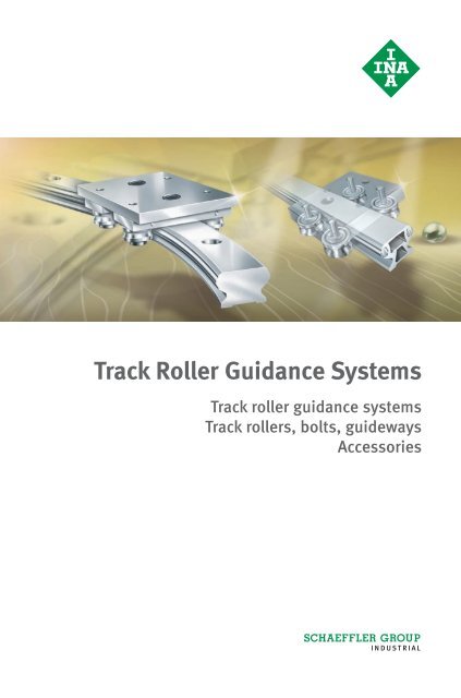
Track Roller Guidance Systems
Track Roller Guidance Systems
Track Roller Guidance Systems
Create successful ePaper yourself
Turn your PDF publications into a flip-book with our unique Google optimized e-Paper software.
<strong>Track</strong> roller guidance systems<strong>Track</strong> <strong>Roller</strong> <strong>Guidance</strong> <strong>Systems</strong><strong>Track</strong> rollers, bolts, guidewaysAccessories
All data have been prepared with a great deal ofcare and checked for their accuracy. However,no liability can be assumed for any errors oromissions.We reserve the right to make technicalmodifications.© Schaeffler KG · 2008, MarchReproduction in whole or in part withoutour authorisation is prohibited.
ContentsPageSafety guidelines and symbols ................................................ 4Product index .......................................................................... 6Product overview..................................................................... 8<strong>Track</strong> roller guidance systems ................................................. 10Technical principles............................................................ 10<strong>Track</strong> roller guidance systemsWith hollow section carriage .......................................... 42With compact carriage.................................................... 43With open carriage ......................................................... 44With non-locating carriage ............................................. 45With bogie carriage ........................................................ 46<strong>Track</strong> rollers, bolts, guideways............................................ 58Accessories ........................................................................ 90Addresses ............................................................................... 109Schaeffler Group Industrial LF 1 5
PageLFS..-F Guideway, flat guideway.......................................................... 80LFS..-FE Guideway, flat guideway.......................................................... 80LFS..-FH Guideway, flat half guideway................................................... 82LFS..-FHE Guideway, flat guideway.......................................................... 82LFS..-FHEE Guideway, flat guideway.......................................................... 82LFS..-M Guideway, profiled section guideway ...................................... 84LFS..-N Guideway with slots ................................................................ 84LFS..-NZZ Guideway with slots ................................................................ 84LFS..-RB Guideway, corrosion-resistant design...................................... 80LFSR..-St Guideway, curved guideway element....................................... 86LFS..-OV../180-VBS Closed oval track with 180° arcs and guideway connector ....... 88LFS..-OV../90-VBS Closed oval track with 90° arcs and guideway connector ......... 88LFZ Concentric bolt........................................................................ 76LFZ..-A1 Concentric bolt with relubrication hole .................................... 76MU T-nut ....................................................................................... 98MU..POS Positionable T-nut ................................................................... 98NAD Slot closing strip for LFS..-M .................................................... 108PAH Stop for guideways.................................................................. 106PASTP Stop for guideways.................................................................. 105SHR T-bolts..................................................................................... 98SPPR Fixing lug................................................................................. 98VBS Guideway connector for guideways ......................................... 99Schaeffler Group Industrial LF 1 7
Technical principles<strong>Track</strong> roller guidance systemsWith hollow section carriageWith compact carriageWith open carriageWith non-locating carriageWith bogie carriage<strong>Track</strong> rollersLocating track rollerNon-locating track rollerBoltsConcentricEccentricGuidewaysWith solid or hollow section profileFlat designWith support railWith slotsHalf guidewayCurved guideway elementAccessories121 672121 668121 670121 653Appendix
Technical principlesLoad carrying capacity and lifeLubricationDesign of bearing arrangementsFittingAccuracyOrdering designationsOperating limits
Technical principlesLoad carrying capacityand lifePagePermissible radial loads ............................................................ 12Permissible radial load under dynamic loading..................... 12Permissible radial load under static loading ......................... 12Fatigue limit load.................................................................. 12Life calculation.......................................................................... 13Life values for track rollers .................................................... 13Operating life........................................................................ 15Static load safety factor ........................................................ 16Minimum load ...................................................................... 16Differences in raceway hardness........................................... 17Lubrication Lubrication of guideway raceways ............................................. 18Lubrication intervals ............................................................. 18Lubrication of track rollers .................................................... 18Design of bearingarrangementsRequirements for the adjacent construction .............................. 19Shaft creep ........................................................................... 19Displacement force............................................................... 19Location of carriages and guideways .................................... 19<strong>Track</strong> roller guidance systems in accordancewith customer specifications ................................................ 20Fitting Delivered condition ................................................................... 24Fitting of guidance system with one guideway ........................... 24Fitting of guidance system with two guideways.......................... 24Fitting of bogie carriages ........................................................... 25Accuracy Accuracy of guideways LFS ........................................................ 27Ordering example,ordering designationReady-to-fit systems.................................................................. 31Closed oval tracks ..................................................................... 32Oval track with 2180° arcs................................................. 32Oval track with 490° arcs................................................... 33Individual components.............................................................. 34Operating limits Operating temperature .............................................................. 35Speeds...................................................................................... 35Acceleration .............................................................................. 35Schaeffler Group Industrial LF 1 11
Load carrying capacity and lifePermissible radial loadsPermissible radial loadunder dynamic loadingAttention!The thick-walled outer rings of the track rollers can support highradial loads. If these track rollers are used against a shaft as araceway, the outer rings undergo elastic deformation, Figure 1.Compared to rolling bearings supported in a housing bore,track rollers have the following characteristics:■ modified load distribution in the bearing.This is taken into consideration by the basic load ratings C rw andC 0r w that are decisive for life calculation.■ bending stress in the outer ring.This is taken into consideration by the permissible radialloads F rper and F 0r per . The bending stresses must not exceedthe permissible strength values of the material (due to the risk offracture).For bearings under dynamic circumferential load, the effectivedynamic load rating C rw is used.C rw is used to calculate the basic rating life.The permissible dynamic radial load F rper must not be exceeded.If the basic static load rating C 0r w is lower than the basic dynamicload rating C rw , C 0r w is used.121 603Figure 1Deformation of the outer ring whenused against a flat racewayPermissiblestatic radial loadAttention!For bearings under static load, when stationary or with onlyinfrequent motion, the effective static load rating C 0r w is used.C 0r w is used to calculate the static load safety factor S 0 .The permissible static radial load F 0r per must not be exceeded.In addition to the permissible radial load of the bearing,the permissible radial load of the mating track must also be takeninto consideration.The basic load ratings stated are valid only in conjunction with ashaft as a mating track that is hardened (at least 670 HV) andground (R a 0,3).Fatigue limit load The fatigue limit load C ur w is defined as the load below which –under laboratory conditions – no fatigue occurs in the material.12 LF 1 Schaeffler Group Industrial
Calculation of the rating lifeLife values for track rollersThe general methods for calculating the rating life are:■ the basic rating life to DIN ISO 281■ the adjusted rating life to DIN ISO 281■ the expanded calculation of the adjusted reference life toDIN ISO 281-4.These methods are described in Catalogue HR1, Rolling Bearings,in the section Technical Principles, Load carrying capacity and life.In comparison with Catalogue HR1, Rolling Bearings, the followingvalues must be exchanged:■ C r =C rw■ C 0r =C 0r w■ C ur = C ur w .The carriages LFCL, LFL..-SF, LFLL, LFKL and the bogie carriage LFDLcontain four track rollers LFR.The equivalent principle applies here.The corresponding parameters are taken into consideration inthe basic load ratings C y , C 0y , C z , C 0z and the permissible momentratings M 0x , M 0y and M 0z .C yNBasic dynamic load rating in y directionC 0yNBasic static load rating in y directionC zNBasic dynamic load rating in z directionC 0zNBasic static load rating in z directionM 0xNmStatic moment rating about X axisM 0yNmStatic moment rating about Y axisM 0zNmStatic moment rating about Z axis.In the case of track rollers with a profiled outer ring, calculation iscarried out exclusively by means of the basic rating life toDIN ISO 281.M 0zC y, C 0yxzM 0xC z, C 0zyFigure 2Load carrying capacityand load directionsxyzx yzM 0y121 686Schaeffler Group Industrial LF 1 13
Load carrying capacity and lifeOther formulae for calculatingthe basic rating lifeL D C p⎛ rw⎞s = 0,0314⋅a⎜⎝ P⎟r ⎠pD CLa ⎛ rw⎞h = 26,18⋅Hn ⋅⎜osc ⎝ P⎟r ⎠pD CLa ⎛ rw⎞h = 52,36⋅v⎜⎝ P⎟r ⎠Rating life for carriageswith four track rollerspCyCzLs= ⎛ , ⎞⎝ ⎜ P⎟⎠p1666 CyCzLh= ⋅ ⎛ , ⎞v ⎝ ⎜ P⎟⎠p833 CyCzLh= ⋅ ⎛ , ⎞Hn ⋅ osc ⎝ ⎜ P⎟⎠L s 10 5Basic rating life in 10 5 metresL hhBasic rating life in operating hoursC rw , C y , C zNEffective dynamic load ratingP rNEquivalent dynamic load (radial load)PNEquivalent dynamic load in corresponding load direction(for applications with combined loads, please contact us)n min –1Operating speedD ammRolling contact diameter of track roller, see dimension tableHmSingle stroke length for reciprocating motionn osc min –1Number of return strokes per minutevm/minMean travel velocityp –Ball: p = 3;needle roller (non-locating track roller or carriage): p = 10 / 3 .14 LF 1 Schaeffler Group Industrial
Operating lifeThe operating life is the life actually achieved by a rolling bearing.It may differ significantly from the calculated rating life.This may be due to wear or fatigue as a result of:■ deviations in the operating data■ insufficient or excessive operating clearance (roller, guideway)■ contamination■ inadequate lubrication■ operating temperature too high or too low■ reciprocating motion with very small stroke length, which canlead to false brinelling■ vibration – false brinelling■ very high shock loads (static overloading)■ prior damage during installation.Due to the variety of installation and operating conditions, it isnot possible to precisely determine the operating life in advance.The most reliable way of arriving at a close estimate is bycomparison with similar applications.Schaeffler Group Industrial LF 1 15
Load carrying capacity and lifeStatic load safety factor The parameter for static loading is the static load safety factor S 0 .This indicates the security against impermissible permanentdeformations in the bearing and is determined by means of thefollowing formula:C0rwS0=F0rStatic load safety factorfor carriages with four track rollersAttention!Minimum loadAttention!CS r0 = 0F0MS0= 0MS 0NStatic load safety factorC 0r wNEffective static load rating according to dimension tableF 0rNMaximum radial load on track rollerC 0rNBasic static load rating according to dimension tableF 0NMaximum load in x, y, z directionM 0NmPermissible static moment in x, y, z directionMNmEquivalent static moment rating in load direction (M x , M y , M z ).<strong>Track</strong> rollers are regarded as heavily loaded at a static load safetyfactor of S 0 4.For applications with normal operating conditions, a value S 0 4 isrequired.When using individual track rollers, for example in conjunction withguideways, the permissible load of the guideway should be taken asdecisive where necessary.Static load safety factors S 0 1 lead to plastic deformations of therolling elements and raceway, which can impair smooth running.This is only permissible for bearings with small rotary motions or insecondary applications.In order to ensure that the outer ring is driven and to preventslippage or lifting of the track roller from the mating track,the track rollers must be subjected to a minimum load in dynamicoperation.In general, the minimum load is determined by the ratioC 0r w /F r 60.16 LF 1 Schaeffler Group Industrial
Differences in racewayhardnessIf shafts with a lower surface hardness are used (such as X46, X90),a hardness factor must be applied, see formula and Figure 3.CH= fH⋅CC0H= f0H⋅C0CNBasic dynamic load ratingC 0NBasic static load ratingC HNEffective dynamic load ratingC 0HNEffective static load ratingf H –Dynamic hardness factorf 0H –Static hardness factor. LFS..-RB, W..-X90 W..-X46f 0H , f H = hardness factorHV, HRC = surface hardnessFigure 3Static and dynamichardness factors for lowerhardness of racewaysf 0Hf H10,90,80,70,60,50,40,30,20,1f 0H0200 250 300 350 400 450 500 550 600 650 700HVHV, HRCf H20 25 30 35 40 45 50 55 HRC 6021160 051Schaeffler Group Industrial LF 1 17
LubricationLubricationof guideway racewaysLubrication intervalsAttention!Lubrication of track rollersFurther informationon lubricationThe guideway raceways must be lubricated (even before first use).Lubrication can be carried out by means of lubrication and wiperunits.These units are already integrated in the compact carriage LFKL.For carriages LFL and LFCL, the lubrication and wiper unit AB isavailable as an accessory, page 94.The guideway raceway is lubricated by an oil-soaked felt insert.Oil can be fed to the felt inserts via lubrication nipples in theend faces. At delivery, the felt inserts are already soaked with oil(H1 approval for the food industry), where relubrication is to becarried out an oil of vicosity 460 mm 2 /s is recommended.The lubrication intervals for guideway raceways are dependent onthe environmental influences. The cleaner the environment,the smaller the quantity of lubricant required. The time and quantitycan only be determined precisely under operating conditions sinceit is not possible to calculate all the influences in advance.A sufficiently long observation period must be allowed.Fretting corrosion is a consequence of inadequate lubrication and isvisible as a reddish discolouration of the mating track or outer ring.Inadequate lubrication can lead to permanent system damage andtherefore to failure. It must be ensured that the lubrication intervalsare reduced accordingly in order to prevent fretting corrosion.In general, a thin film of oil should always be present on the shaft.At delivery, track rollers LFR have an initial greasing of a high qualitylithium soap grease.From LFR5204-16, the inner ring has a relubrication hole.The smaller track roller diameters are lubricated for life.Further information can be found in Catalogue HR1,Rolling Bearings, in the section Lubrication.Figure 1Lubricationof guideway raceways155 26718 LF 1 Schaeffler Group Industrial
Design of bearing arrangementsRequirementsfor the adjacent constructionThe running accuracy of the linear guidance system is essentiallydependent on the straightness, accuracy and rigidity of themounting surfaces.The higher the requirements for accuracy and smooth running of atrack roller guidance system, the more attention must be paid to thegeometrical and positional accuracy of the adjacent construction.The adjacent surfaces should be flat and have parallel faces.For two guideways, we recommend parallelism to Figure 1.0,02Figure 1Parallelism of guidewaysShaft creepDisplacement forceLocation of carriagesand guidewaysUnder unfavourable conditions, shaft creep of a few millimetres mayoccur in isolated cases. This creep may occur mainly in applicationswith high accelerations in conjunction with high alternating loadsand guideways that are not completely supported. It may also becaused by an adjacent construction that is too soft.In such cases, shaft creep can be prevented by the use of endplates ANS.LFS; for information on end plates, see page 100.They can be supplied already mounted.The displacement force is dependent on the preload, the lubricationand the particular application. It is therefore not possible to makegenerally valid statements.If lateral loads are present, it is recommended that the guidewaysand carriages should be located against locating surfaces. In thecase of guideways comprising multiple sections joined together, itis recommended that the guideways should be aligned by means ofthe shaft. If necessary, the shafts should be located on the adjacentconstruction by means of dowels.If two guideways are arranged in parallel, the first guideway shouldbe clamped against a stop, Figure 1. The second guideway shouldthen be aligned accordingly. Any gaps between the guideway andthe adjacent construction should be filled with resin.121 269Schaeffler Group Industrial LF 1 19
Design of bearing arrangements<strong>Track</strong> roller guidance systemsin accordancewith customer specificationsThe INA track roller guidance systems with curved guidewayelements can be used to achieve an extremely wide variety ofapplications, Figure 2 and Figure 3.If the arrangement required cannot be represented using thestandard ordering designation, a customer drawing must besubmitted with the enquiry.For arrangements with curved guideway elements, it isrecommended that the guideway connector VBS should beused at the joints, see page 99. This gives considerably easiermounting.Figure 2Arrangement accordingto customer requirements121 55220 LF 1 Schaeffler Group Industrial
Figure 3Closed and open applicationswith guidance systems includingcurved guideway elements121 610Schaeffler Group Industrial LF 1 21
Design of bearing arrangementsPossible combinationsof profiled track rollers withshaft and support rail unitsShaft and support rail units121 365Shaftdiametermm1) With AB.W: t max = 2,5.TSNW, TSNW..-G4, -G5Fixing screws Load case, Figure 4I II III12 DIN ISO 4762 ■ – –DIN 7984 ■ ■ ■16 DIN ISO 4762 ■ – –DIN 7984 ■ – –20 DIN ISO 4762 ■ – –DIN 7984 ■ – –25 DIN ISO 4762 ■ ■ ■DIN 7984 ■ ■ ■30 DIN ISO 4762 ■ – –DIN 7984 ■ ■ ■40 DIN ISO 4762 ■ ■ ■DIN 7984 ■ ■ ■50 DIN ISO 4762 ■ ■ ■DIN 7984 ■ ■ ■■ Combination possible if the rail is located using the stated screw.● Combination possible.❍ Combination possible if t t max and b b max .– Please contact us.22 LF 1 Schaeffler Group Industrial
tt121 366121 367120 515aTSUW TSSW TSMWt max b max Load case, Figure 4 t max Load case, Figure 4 Load case, Figure 4I II III I II III I II IIImm mm mm 1)5 5 ● ❍ 1) – – – – – – –– – ● – – – – – – – – –– – ● – – – ● – – ● – –10 12 ● ● ❍ 36 ● ● ● ● ● ●12 16 ● ● ❍ 42 ● ● ● ● ● ●10 – ● ● ❍ 50 ● ● ● – – –13 – ● ● ❍ 70 ● ● ● – – –Attention!When combining these components, the following factors must betaken into consideration:■ the static load safety factor S 0 , page 16■ the load cases according to Figure 4■ a shaft hardness of 670 HV.S 4 0S 0 =C 0w /P 0Figure 4Load cases I, II and IIIS 6 0S 6 0121 364Schaeffler Group Industrial LF 1 23
FittingDelivered conditionCarriagesFitting of guidance systemwith one guidewayFitting of guidance systemwith two guidewaysCarriages are delivered with the track rollers fitted. All the bolts aretightened to the required tightening torque.For carriages, this gives the following characteristics:■ hollow section carriage LFCL;clearance-free, with mounting of accessories as necessary.■ compact carriage LFKL..-SF;clearance-free, with mounting of lubrication and wiper unitas necessary.■ non-locating carriage LFLL..-SF;clearance-free, with mounting of accessories as necessary.■ open carriage LFL..-SF;clearance-free, with mounting of accessories as necessary.■ bogie carriage LFDL..-SF, LFDL..-B;LFDL..-SF clearance-free, with mounting of accessories asnecessary.In the case of LFDL..-B, the clearance must be setby means of the eccentric bolts.■ Place the guideway on the adjacent construction and screwmount finger tight.■ Align the guideway; if necessary, clamp the shaft against thelocating edge and screw mount firmly, observing the tighteningtorques.■ Clearance-free carriages: slide the carriage onto the guideway.■ Carriages with adjustable clearance:if lateral load is present, ensure that the principal loadis supported by the concentric bolts.■ Position and screw mount the adjacent construction.■ Position the first guideway, clamp it against the locating edgeand tighten the screws.■ Position the second guideway and tighten the screws finger tight.■ Slide the carriage onto the guideway, set the clearanceif necessary, Figure 2, page 25.■ Position the adjacent construction, align the carriage and screwmount firmly; observe the tightening torques M A , table page 26.■ Align the second guideway with the aid of the table,move the table several times during this operation.■ Tighten the fixing screws in the guideway;tightening torques M A , table page 26.Where necessary, physical locking can be achieved between theguideways and adjacent construction by means of resin or strips.24 LF 1 Schaeffler Group Industrial
Fitting of bogie carriagesCarriageswith adjustable clearanceAttention!InspectionSlide the clearance-free carriage LFDL..-SF onto the guideway.No setting of clearance is required, Figure 1.Slide the carriage LFDL..-B onto the guideway and set in positionwithout load. Rotate the eccentric bolts using an open-end wrenchor ring wrench so that the track rollers are set against the raceway,observing the direction of rotation, Figure 2.Tighten the hexagonal nut to the tightening torque M A ;tightening torques, table Tightening torques for track roller bolts,page 26.The track rollers must be easily movable and clearance-free.If they are set in place too firmly, this will generate preload thatreduces the life of the guidance system.Check the adjustment. The guidance system is correctly adjusted if,when the carriages are moved, all the track rollers rotate and thecarriages can be moved easily.The concentric bolts are tightened to the necessary tighteningtorque, the eccentric bolts are tightened finger tight. When settingthe preload, these must be tightened to the tightening torque M A ,table page 26.Figure 1Clearance-free carriage LFDL..-SF156 541a121 626aFigure 2Carriage with adjustableclearance LFDL..-BSchaeffler Group Industrial LF 1 25
FittingTightening torquesfor track roller boltsTightening torquesfor screws in carriageto DIN ISO 4 762-8.8Tightening torquesfor screws in guideways LFSto DIN ISO 4 762-8.8or DIN 7 984-8.8<strong>Track</strong> roller,profiled trackrollerBoltTightening torqueM AStandard (-2Z)NmRB (-2RSR)NmLFR50/5-4 M4 2,5 2,5LFR50/5-6 M4 2,5 2,5LFR50/8-6 M8 15 12LFR5201-10 M10 40 23LFR5301-10 M10 40 23LFR5302-10 M12 70 39LFR5201-12 M10 40 23LFR5204-16 M16X1,5 100 75LFR5206-20 M20X1,5 200 100LFR5206-25 M20X1,5 200 100LFR5207-30 M24X1,5 300 150LFR5208-40 M30X1,5 600 310LFR5308-50 M30X1,5 800 410ScrewTightening torqueM ANmM5 5,8M6 9,9M8 24M10 48M12 83ScrewTightening torqueM ANmM5 5,8M6 9,9M8 24M10 48M12 8326 LF 1 Schaeffler Group Industrial
AccuracyAccuracyof guideways LFSLength toleranceStraightness toleranceof guidewaysData on the straightness, parallelism (differential measurement),length and positional tolerances of guideways are given in thefollowing tables and figures, Figure 1 to Figure 5.The guideways are precision straightened and the tolerances arebetter than DIN EN 12 020.LmmTolerancemmSingle-piece guideways L 1 000 21000 L 2 0002000 L 4 0004000 LMulti-piece guideways Total length L 0,1%Length of guideway t 1(contact face)t 2(lateral)mmmmL 1 000 0,5 0,21 000 L 2 000 1 0,32 000 L 3 000 1,5 0,43 000 L 4 000 2 0,54 000 L 5 000 2,5 0,65 000 L 6 000 3 0,76 000 L 7 000 3,5 0,87 000 L 8 000 4 0,93450,020,08 AB0,1 B ConcaveFigure 1Tolerances for guideways LFS,LFS..-C, LFS..-R, LFS..-N, LFS..-NZZh 4A0,2/ 1t /L0,10,08 A0,02B0,1 Bh 4A0,2/ 1nj Lj L 0,5L1t /L 2121 658Schaeffler Group Industrial LF 1 27
Accuracy0,020,08 AB0,1 Bh 4A10,2/ 2t /L 1Lj L Contact face indicated by slot Concavenj Lt /L 2Figure 2Guideway LFS..-F 0,5121 6590,020,08 AB0,1Bh4A0,2/ 2t 1/ LParallelism determinedby differential measurement Concavej Bj L2 0,5t / LFigure 3Guideway LFS120L121 26328 LF 1 Schaeffler Group Industrial
0,0350,08 AB0,1 Bh 4A0,2/ 2t /L 1Parallelism determinedby differential measurement ConcaveFigure 4Guideway LFS..-MLt /L 2121 2640,10,10,080,08h 40,2/ 20,2/ 21h 4t /LL1t /L 2j Bnj B 0,5 Contact face indicated by slot ConcaveFigure 5GuidewaysLFS..-FH and LFS..-CH121 265Schaeffler Group Industrial LF 1 29
AccuracyTolerances for H 2 and h 4 are shown in the table, Figure 6 andFigure 7.Tolerance for h 4 Guideway H2 h 4mmmmLFS20–0,1LFS25 –0,1LFS25-N –0,1LFS25-M 0,25LFS32 +0,2LFS32-C +0,2LFS32-N +0,2LFS32-F +0,1LFS32-M 0,25LFS32-CH +0,2LFS32-FH +0,1+0,3LFS42-C +0,2LFS42-FH +0,1LFS52 +0,2LFS52-C +0,2LFS52-NZZ +0,2LFS52-F +0,1LFS52-M +0,5LFS52-CH +0,2LFS52-FH +0,1LFS86-C +0,25LFS120 +0,2H 2Tolerance for H 2 = +0,3 mmFigure 6Reference dimension for accuracy,dimension H 2121 270h 4Figure 7Reference dimension for accuracy,dimension h 4121 34530 LF 1 Schaeffler Group Industrial
Ordering exampleOrdering designationReady-to-fit systemsOrdering exampleCarriageOrdering designationThe elements of the track roller guidance systems(such as the carriage, guideway) must be ordered separately.Carriages should be regarded as a unit, including the track rollersand bolts.Carriages and guideways can be used in any combination and canbe ordered independently of each other.<strong>Track</strong> roller guidance system, corrosion-resistant design,with open carriage LFL52-E-SF, Figure 1 and Figure 2.CarriageLFLSize 52-EClearance-freeSFCorrosion-resistant RBLFL52-E-SF-RBFigure 1Open carriage LFL52-E-SFGuidewayOrdering designationHollow section guideway LFS52-CE, length 1500 mm,a L = 50 mm, a R = 75 mm, in corrosion-resistant design, Figure 2:GuidewaysLFSWidth of guideway 52TypeCELength of guideway l 1 500Spacing a L 50Spacing a R 75Corrosion-resistant RBLFS52-CE/1500-50/75-RB121 660a L=50j La R=75Figure 2Guideway LFS52-CE121 625Schaeffler Group Industrial LF 1 31
Oval track with 490° arcsOrdering designationGuidewaysLFSWidth of guideways a52 mmClosed oval trackOVRadius of arc300 mmArc angle 90°Length of– 1. straight guideway pair– 2. straight guideway pair2 000 mm3 000 mm, Figure 4Without guideway connectors VBS1LFS52-OV-300/90–2 000/3 000With guideway connectors VBS1LFS52-OV-300/90–2 000/3 000.VBSa2000a = width of guidewaysr 30090°Figure 4Closed oval trackwith 90° arcsLFS52-OV-300/90–2 000/3 0003000121 580Schaeffler Group Industrial LF 1 33
Ordering exampleOrdering designationIndividual components<strong>Track</strong> rollerOrdering designationBoltsOrdering designationCap wiperOrdering designationIn order to achieve versatile user designs, it is also possible to orderindividual components of the ready-to-fit systems,for example see Figure 5.SeriesLFRSize 50/8-6Seals2RSRCorrosion-resistant RB, Figure 5LFR50/8-6-2RSR-RBSeriesLFConcentricZSize 8Corrosion-resistant RB, Figure 5LFZ8-RBSeriesAB.LFRSize 50/8, Figure 5AB.LFR50/81 234 <strong>Track</strong> roller Bolt, concentric Bolt, eccentric Cap wiperFigure 5<strong>Track</strong> roller, bolts, wiper121 64934 LF 1 Schaeffler Group Industrial
Operating limitsOperating temperatureSpeedsAcceleration<strong>Track</strong> roller guidance systems can be used at temperatures from–20 °C to +80 °C. For applications below –20 °C or above +80 °C,please contact us.The area of application is restricted by the lubricant, the plasticsused and the composite materials.The maximum possible speed of track roller guidance systems is10 m/s. Higher speeds may be possible by agreement.When using track roller guidance systems, accelerations of up to50 m/s 2 can be achieved.Schaeffler Group Industrial LF 1 35
<strong>Track</strong> roller guidance systemsWith hollow section carriageWith compact carriageWith open carriageWith non-locating carriageWith bogie carriage
<strong>Track</strong> roller guidance systemsPageMatrix Matrix for preselection of track roller guidance systems............. 38Product overview <strong>Track</strong> roller guidance systems ................................................... 40Features <strong>Track</strong> roller guidance system with hollow section carriage ......... 42<strong>Track</strong> roller guidance system with compact carriage .................. 43<strong>Track</strong> roller guidance system with open carriage........................ 44<strong>Track</strong> roller guidance system with non-locating carriage ............ 45<strong>Track</strong> roller guidance system with bogie carriage ....................... 46Dimension tables <strong>Track</strong> roller guidance system with hollow section carriage ......... 48<strong>Track</strong> roller guidance system with compact carriage .................. 50<strong>Track</strong> roller guidance system with open carriage........................ 52<strong>Track</strong> roller guidance system with non-locating carriage ............ 54<strong>Track</strong> roller guidance system with bogie carriage ....................... 56Schaeffler Group Industrial LF 1 37
Matrix for preselectionof track roller guidance systems<strong>Track</strong> roller guidance systemswithWidth of guideways20 25 32 42 52 86CorrosionresistantHollowsectioncarriageLFCL– ● – ● – ● ■CompactcarriageLFKL..-SF● ● ● – ● – ■OpencarriageLFL..-SF● – ● – ● – ■Non-locatingcarriageLFLL..-SF– – ● – ● – ■BogiecarriageLFDL..-SFLFDL..-B– – ● – ● – ■121 661121 597a121 470a121 471a121 469a● Available sizes.■ Possible.1) The guideway LFS..-M can only be combined with carriages with adjustable clearance.If SF and LFCL carriages are to be used, please contact us first.38 LF 1 Schaeffler Group Industrial
Particular featuresof guidance systemsSizes– Economical25– Low mass42– High moment load86carrying capacity M xBasic dimensions of guidance systems,for dimensioning see Figure 1LFS, -C, -CE, -CEE,-E, -EE, -N, -NZZLFS..-F, -FE LFS..-M 1)DescriptionH B L H B L H B L See page32,1395980116190110150235–33,9–8011619011015023563,1––8011619011015023542– Closed series– Protected track rollers– Integated lubrication unit2025325252-E52-EE222535,554,360,460,4566586131451556985112136186205––25,538,244,344,3566586131451556985112136186205–56–118,912512556658613145155698511213618620543– Very robust– Simple construction20325252-E2235,554,360,455801201355090100150–25,538,244,355801201355090100150–81,5118,91255580120135509010015044– Locating/non-locatingbearing arrangement– Compensation of parallelismdeviations up to 1 mm325235,554,3801209010025,538,2801209010081,5118,9801209010045– Oval track guidance systemsfor unlimited stroke length32-B32-SF52-B52-SF44,244,266,160,1808012012010010015015034,234,25050808012012010010015015090,290,2130,7130,7808012012010010015015046BLHFigure 1Dimensions H, B, L121 651Schaeffler Group Industrial LF 1 39
Product overview<strong>Track</strong> roller guidance systemsWith hollow section carriageClearance-freeLFCL121 469With compact carriageClearance-freeLFKL..-SF121 471With open carriageClearance-freeLFL..-SF121 47040 LF 1 Schaeffler Group Industrial
With non-locating carriageClearance-freeLFLL..-SF121 597With bogie carriageConcentric andeccentric bolts,adjustable clearanceLFDL..-B121 627Concentric boltsClearance-freeLFDL..-SF121 626Schaeffler Group Industrial LF 1 41
<strong>Track</strong> roller guidance systemsFeatures<strong>Track</strong> roller guidance systemwith hollow section carriage<strong>Track</strong> roller guidance systems are available with a hollow sectioncarriage, compact carriage, open carriage, non-locating carriage orbogie carriage.The economical series LFCL is characterised in particular by its lowmass and high moment load carrying capacity M x . In addition, moreindividual design of the adjacent construction is possible since theT-bolts can be moved longitudinally in the carriage plate.A carriage comprises a carriage plate made from anodisedaluminium, four concentric bolts, four track rollers, two end coversfor the hollow sections and eight T-nuts, Figure 1. The track rollersand end covers are already fitted.Preload and clearance The carriages run clearance-free on all INA guideways, see page 38,and can be combined with all guideways of the relevant size, but notwith the curved guideway elements LFSR.Due to the highly accurate guideways, it is not necessary to setthe clearance.Sealing and lubricationCorrosion-resistant designFurther informationThe track rollers have gap seals on both sides, are greased for lifeand are therefore maintenance-free.The raceways can be lubricated using cap wipers AB..-LFR.Their fixing screws pass into the screw mounting channels of thecarriage plate.All steel parts, the inner and outer rings of the track rollers and thebolts, washers and nuts are made from corrosion-resistant steel.The rolling elements are protected against corrosion by the grease.Corrosion-resistant designs have the suffix RB.Further information is given on the following pages:■ dimension table see page 48■ track rollers and bolts see page 60, 64■ guideways see page 66■ accessories see page 92. T-nut End cover Carriage plate <strong>Track</strong> roller Concentric bolt2143Figure 1Hollow section carriage5121 33842 LF 1 Schaeffler Group Industrial
<strong>Track</strong> roller guidance systemwith compact carriageThe closed compact carriage LFKL..-SF gives a simple means ofachieving track roller guidance systems for operation incontaminated environments. The track rollers are protectedagainst contamination by the closed design. It has two integratedlubrication units for lubrication of the raceways.A compact carriage comprises a saddle plate made from anodised,profiled aluminium, four concentric bolts, four track rollers,two sealing strips and two lubrication and wiper units, Figure 2.The track rollers are already fitted, the sealing strips as well as thelubrication and wiper units are included loose in the delivery.Preload and clearance The carriages run clearance-free on all INA guideways, see page 38,and can be combined with all guideways of the relevant size,but not with the curved guideway elements LFSR. Due to the highlyaccurate guideways, it is not necessary to set the clearance.Sealing and lubricationCorrosion-resistant designFurther informationThe track rollers have gap seals on both sides, are greasedfor life and are therefore maintenance-free.For lubrication of the raceways, the lubrication and wiper units haveoil-soaked felt insert that can be replenished with oil via lubricationnipples. In combination with the sealing strips (gap seals),these units protect the compact carriage on all sides againstcontamination.All steel parts, the inner and outer rings of the track rollers and thebolts, washers and nuts are made from corrosion-resistant steel.The rolling elements are protected against corrosion by the grease.Corrosion-resistant designs have the suffix RB.Further information is given on the following pages:■ dimension table see page 50■ track rollers and bolts see page 60, 64■ guideways see page 66■ accessories see page 92.5 Sealing strip Lubrication and wiper unit <strong>Track</strong> roller Concentric bolt Saddle plateFigure 2Compact carriage1234121 312Schaeffler Group Industrial LF 1 43
<strong>Track</strong> roller guidance systems<strong>Track</strong> roller guidance systemwith open carriageThe robust open carriage LFL..-SF is suitable where efficient linearguidance systems of a simple construction are required.A carriage comprises a carriage plate made from anodisedaluminium, four screws and four track rollers, Figure 3.The track rollers are already fitted.Preload and clearance The carriages run clearance-free on all INA guideways, see page 38,and can be combined with all guideways of the relevant size,but not with the curved guideway elements LFSR. Due to the highlyaccurate guideways, it is not necessary to set the clearance.Sealing and lubricationCorrosion-resistant designFurther informationThe track rollers have gap seals on both sides, are greasedfor life and are therefore maintenance-free.The raceways can be lubricated by means of lubrication and wiperunits AB, page 92. Their oil-soaked felt inserts can be replenishedwith oil via lubrication nipples. In combination with sideplates ABAL, these units seal the end faces and longitudinal sidesof the open carriage, page 93.All steel parts, the inner and outer rings of the track rollers and thescrews, washers and nuts are made from corrosion-resistant steel.The rolling elements are protected against corrosion by the grease.Corrosion-resistant designs have the suffix RB.Further information is given on the following pages:■ dimension table see page 52■ track rollers and screws see page 60, 64■ guideways see page 66■ accessories see page 92.1121 662 Carriage plate Screws <strong>Track</strong> rollerFigure 3Open carriage3244 LF 1 Schaeffler Group Industrial
<strong>Track</strong> roller guidance systemwith non-locating carriageNon-locating carriages LFLL..-SF are robust, ready-to-fit linearguidance systems that are used exclusively in locating ornon-locating bearing applications with two parallel guidewaysystems. The track rollers can be axially displaced. In this way,it is possible to compensate for inaccuracies of 1 mm in relationto the spacing of the guideways.A carriage comprises a carriage plate made from anodisedaluminium, four screws and four non-locating track rollers, Figure 4.The track rollers are already fitted.Preload and clearance The carriages run clearance-free on all INA guideways, see page 38,and can be combined with all guideways of the relevant size,but not with the curved guideway elements LFSR. Due to the highlyaccurate guideways, it is not necessary to set the clearance.Sealing and lubricationCorrosion-resistant designAttention!Further informationThe track rollers have gap seals on both sides, are greasedfor life and are therefore maintenance-free.The contact zone between the raceways and track rollers must belubricated via the shaft.All steel parts, the inner and outer rings of the track rollers and thescrews, washers and nuts are made from corrosion-resistant steel.The rolling elements are protected against corrosion by the grease.Corrosion-resistant designs have the suffix RB (available byagreement only).Non-locating carriages must never be used on their own but onlyever in combination with locating carriages.The track rollers can support loads in a radial direction only.Further information is given on the following pages:■ dimension table see page 54■ track rollers and screws see page 60, 64■ guideways see page 66■ accessories see page 92.121 583a Carriage plate Screw Non-locating track roller1 2 3Figure 4Non-locating carriageSchaeffler Group Industrial LF 1 45
<strong>Track</strong> roller guidance systems<strong>Track</strong> roller guidance systemwith bogie carriagePreload and clearanceSealing and lubricationCorrosion-resistant designAttention!Further informationBogie carriages LFDL can be used in combination with curvedguideway elements LFSR to achieve almost any variant of oval andcircular track guidance systems. The straight guideway elements areprecisely matched to the arc. The carriages are available in thedesign LFDL..-SF (with four concentric bolts) and design LFDL..-B(two concentric and two eccentric bolts).A carriage comprises a steel carriage plate, two aluminium swivelbrackets (supported axially and radially by rolling bearings), fourconcentric bolts or two concentric and two eccentric bolts, Figure 5.The track rollers are already fitted.The carriage LFDL..-B is set clearance-free in relation to the guidewayby means of the eccentric bolts.Carriage LFDL..-SF cannot be adjusted, since the carriage is alreadyoptimally adjusted to the INA guideways, see page 38.The track rollers have gap seals on both sides, are greasedfor life and are therefore maintenance-free.The contact zone between the raceways and track rollers must belubricated via the shaft.All steel parts, the inner and outer rings of the track rollers and thebolts, washers and nuts are made from corrosion-resistant steel.The rolling elements are protected against corrosion by the grease.Corrosion-resistant designs have the suffix RB (available byagreement only).The adjustable carriage LFDL..-B must be used in combination witha 360° guideway.Further information is given on the following pages:■ dimension table see page 56■ track rollers and bolts see page 60, 64■ guideways see page 66■ accessories see page 92.12 Carriage plate Bracket <strong>Track</strong> roller Concentric bolt34Figure 5Bogie carriage121 66446 LF 1 Schaeffler Group Industrial
Schaeffler Group Industrial LF 1 47
<strong>Track</strong> roller guidance systemswith hollow section carriageLJ L1zyxJ BLFCL with LFS, -C, -CE, -CEE, -E, -EE, -N, -NZZ, -M, -FView rotated 90°J L3G4121 253Dimension table · Dimensions in mmCarriage 1) Mass <strong>Track</strong> roller 3) ForDimensionsMounting dimensionsshaftmdiameterH 1 B L J B J B1 J B2 J L1kgLFCL25 0,44 LFR50/8-6-2Z 6 30,5 80 110 47 47 69 52LFCL42 1 LFR5201-10-2Z 10 38,1 116 150 73 73 98,5 85LFCL86 2) 2,2 LFR5301-10-2Z 10 48,4 190 235 124 124 151,5 155Ordering designationsCorrosion-resistant design: LFCL..-RB, LFS..-RB with LFR..-2RSR-RBGuideways without holes: LFS..-OL.1) The design of the hollow sections is dependent on the size.2) Additional T-slot in the centre of the carriage.3) For ordering of replacement parts, please contact us.4) The guideway LFS..-M can only be combined with carriages with adjustable clearance.If SF and LFCL carriages are to be used, please contact us first.Basic load ratings 1)CarriageGuideway<strong>Track</strong> roller 2)Basic load ratings1) For basic load ratings in combination with LFS..-RB, see page 17.2) For ordering of replacement parts, please contact us.C y C 0y C z C 0z M 0x M 0y M 0zN N N N Nm Nm NmLFCL25 LFS25 LFR50/8-6-2Z 4 600 2 400 7 320 4 500 25 120 65LFCL42 LFS42 LFR5201-10-2Z 10 200 5 480 16 900 10 000 85 425 230LFCL86 LFS86 LFR5301-10-2Z 17 800 8 850 28 400 15 500 335 1190 68048 LF 1 Schaeffler Group Industrial
BJ B2J B1H 1H 2H 3BJ B2J B1H 1H 2H 3H1H1121 252121 585LFCL with LFS, -C, -CE, -CEE, -E, -EE, -N, -NZZ Threaded slot for screws M3LFCL with LFS..-M 4) Threaded slot for screws M3J L3 H 2 H 3 G 4 Maximumscrew depth for G 4min. max. +0,3Total height ofcarriage and guidewayLFS, -C, -CE, -CEE,-E, -EE, -N, -NZZLFS-F LFS-M 4)13 26 21,5 15,4 M6 10 32,1 – 63,115 55 26,4 18 M8 12 39 33,9 –18 119 33,9 23,4 M10 14 59 – –C , C 0y yM0zBJ B2J B1xM 0xzC z , C 0zM 0yH 1H 2H 3Hy121 6501121 586Load directionsLFCL with LFS..-F Threaded slot for screws M3Schaeffler Group Industrial LF 1 49
<strong>Track</strong> roller guidance systemwith compact carriageLG4zyG4xJB1JBK2 JL1JL2121 200LFKL with LFS, -C, -CE, -CEE, -E, -EE, -N, -NZZ,-M, -F, -FEView rotated 90°Dimension table · Dimensions in mmCarriage Mass <strong>Track</strong> roller 3) ForDimensionsMounting dimensionsshaftmdiameterH 1 B L J B J B1 K 2kg 0,2LFKL20-SF 2) 0,2 LFR50/5-4-2Z 4 20,5 56 69 39 34 5LFKL25-SF 2) 0,3 LFR50/5-6-2Z 6 23,5 65 85 50 40 5LFKL32-SF 0,7 LFR50/8-6-2Z 6 32 86 112 59 54 7LFKL52-SF 1,5 LFR5201-10-2Z 10 46,1 130 136 90 83 10LFKL52-E-SF 2,9 LFR5301-10-2Z 10 53,8 145 186 105 90 10LFKL52-EE-SF 4,3 LFR5302-10-2Z 10 55 155 205 115 95,2 10Ordering designationCorrosion-resistant design: LFKL..-RB, LFS..-RB with LFR..-2RSR-RBGuideways without holes: LFS..-OL.1) Tightening torque for track roller bolts, concentric bolts are supplied tightened to M A .2) Without lubrication nipple, relubrication possible via end holes.3) For ordering of replacement parts, please contact us.4) The guideway LFS..-M can only be combined with carriages with adjustable clearance.If SF and LFKL carriages are to be used, please contact us first.Basic load ratings 1)CarriageGuideway<strong>Track</strong> roller 2)1) For basic load ratings in combination with LFS..-RB, see page 17.2) For ordering of replacement parts, please contact us.Basic load ratingsC y C 0y C z C 0z M 0x M 0y M 0zN N N N Nm Nm NmLFKL20-SF LFS20 LFR50/5-4-2Z 1 350 870 2 400 1 700 7 28 15LFKL25-SF LFS25 LFR50/5-6-2Z 1 280 820 2 580 1 800 8 40 18LFKL32-SF LFS32 LFR50/8-6-2Z 4 100 2 400 6 600 4 200 30 130 70LFKL52-SF LFS52 LFR5201-10-2Z 10 000 5 200 16 800 10 000 110 290 150LFKL52-E-SF LFS52-E LFR5301-10-2Z 17 800 8 900 28 400 15 500 180 800 460LFKL52-EE-SF LFS52-EE LFR5302-10-2Z 20 000 10 000 32 400 18 200 215 1 100 62050 LF 1 Schaeffler Group Industrial
BBH 2H 1H 3H 2H 1 HH121 199121 588LFKL with LFS, -C, -CE, -CEE, -E, -EE, -N, -NZZLFKL with LFS..-M 4)Total height ofcarriage and guidewayJ L1 J L2 H 2 H 3 G 4 M 1)A LFS, -C, -CE, -CEE,-E, -EE, -N, -NZZStandard0,2 +0,3 Nm NmCorrosionresistantLFS-F, -FE LFS-M 4)34 49 13 8,7 M5 2,5 2,5 22 – –45 60 14,4 9 M5 2,5 2,5 25 – 5660 70 20,5 14 M8 15 12 35,5 25,5 81,560 70 29,2 19,4 M10 40 23 54,3 38,2 118,9105 110 35,3 24 M10 40 23 60,4 44,3 125120 140 35,3 24 M12 70 39 60,4 44,3 125C , C 0y yM0zBM 0xC z , C 0zH 2 H H1xzM 0yy121 650121 427Load directionsLFKL with LFS..-F, -FESchaeffler Group Industrial LF 1 51
<strong>Track</strong> roller guidance systemwith open carriageG 3t 1LG 4 z G 4J B2 JB1Jy xBJ L1J L2LFL with LFS, -C, -CE, -CEE, -E, -EE, -N, -NZZ, -M, -F, -FEView rotated 90°121 204Dimension table · Dimensions in mmCarriage Mass <strong>Track</strong> roller 3) ForDimensionsMounting dimensionsshaftmdiameterH 1 B L J B J B1 J B2 J L1 J L2kg 0,2 0,2LFL20-SF 2) 0,16 LFR50/5-4-2Z 4 20,5 55 50 40 34 – 24 38LFL32-SF 0,4 LFR50/8-6-2Z 6 30 80 90 59 54 56 60 70LFL52-SF 1 LFR5201-10-2Z 10 43,2 120 100 90 83,2 65 60 70LFL52-E-SF 1,9 LFR5301-10-2Z 10 53,8 135 150 105 90 65 105 110Ordering designationCorrosion-resistant design: LFL..-RB, LFS..-RB with LFR..-2RSR-RBGuideways without holes: LFS..-OL.Corrosion-resistant design available by agreement.1) Tightening torque for track roller bolts, concentric bolts are supplied tightened to M A .2) Hole in underside for cap wiper AB LFL20.3) For ordering of replacement parts, please contact us.4) The guideway LFS..-M can only be combined with carriages with adjustable clearance.If SF and LFCL carriages are to be used, please contact us first.Basic load ratings 1)CarriageGuideway<strong>Track</strong> roller 2)1) For basic load ratings in combination with LFS..-RB, see page 17.2) For ordering of replacement parts, please contact us.Basic load ratingsC y C 0y C z C 0z M 0x M 0y M 0zN N N N Nm Nm NmLFL20-SF LFS20 LFR50/5-4-2Z 1 350 870 2 400 1 700 7 20 10LFL32-SF LFS32 LFR50/8-6-2Z 4 100 2 400 6 600 4 200 30 130 70LFL52-SF LFS52 LFR5201-10-2Z 10 000 5 200 16 800 10 000 110 290 150LFL52-E-SF LFS52-E LFR5301-10-2Z 17 800 8 900 28 400 15 500 180 800 46052 LF 1 Schaeffler Group Industrial
BH 1H 3A 4BH 2HH 1H 2A 4H 3H121 201121 587LFL with LFS, -C, -CE, -CEE, -E, -EE, -N, -NZZLFL with LFS..-M 4)Total height ofcarriage and guidewayt 1 H 2 H 3 A 4 G 3 G 4 M 1)A LFS, -C, -CE, -CEE,-E, -EE, -N, -NZZStandard+0,3 Nm NmCorrosionresistantLFS-F, -FE LFS-M 4)– 13 9 – M3 2) M5 2,5 2,5 22 – –7 20,5 14 7 M6 M8 15 12 35,5 25,5 81,512 29,2 19,5 9,75 M6 M10 40 23 54,3 38,2 118,912 35,3 24 12 M6 M10 40 23 60,4 44,3 125C , C 0y yM0zBM 0xC z , C 0zH 1H 2A 4H 3HxzM 0yy121 650121 203Load directionsLFL with LFS..-F, -FESchaeffler Group Industrial LF 1 53
<strong>Track</strong> roller guidance systemwith non-locating carriageG 3t 1LG 4 z G 4J B2 JB1Jy xBJ L1J L2LFLL with LFS, -C, -CE, -CEE, -E, -EE, -N, -NZZ,-M, -F, -FEView rotated 90°121 204Dimension table · Dimensions in mmCarriage Mass For DimensionsMounting dimensionsshaftmdiameterH 1 B L J B J B1 J B2 J L1 J L2 t 1Ordering designationGuideways without holes: LFS..-OL.kg 0,2 0,2LFLL32-SF 0,4 6 32,5 80 90 59 54 56 60 70 7LFLL52-SF 1 10 45 120 100 90 83 65 60 70 12Corrosion-resistant design available by agreement.1) LFLL32-SF: 0,5 axial displacement capacity.2) LFLL52-SF: 1 axial displacement capacity.3) The guideway LFS..-M can only be combined with carriages with adjustable clearance.If SF and LFCL carriages are to be used, please contact us first.Basic load ratings 1)CarriageGuideway<strong>Track</strong> roller 2)1) For basic load ratings in combination with LFS..-RB, see page 17.2) For ordering of replacement parts, please contact us.Basic load ratingsC z C 0z M 0yN N NmLFLL32-SF LFS32 LFR22/8-6-2RSR-RNA + IR6,4X12X17 9 000 8 000 250LFLL52-SF LFS52 LFR2202-10-2RSR-RNA + IR10,5X20X21 17 000 19 000 55054 LF 1 Schaeffler Group Industrial
BH 1H 3A 4BH 2HH 1H 2A 4H 3H121 201121 587LFLL with LFS, -C, -CE, -CEE, -E, -EE, -N, -NZZLFLL with LFS..-M 3)Total height ofcarriage and guidewayH 2 H 3 A 4 G 3 G 4 LFS, -C, -CE, -CEE,-E, -EE, -N, -NZZLFS-F, -FE LFS-M 3)20,5 1) 13,75 7 M6 M8 35,5 1) 25,5 1) 81,5 1)29,2 2) 19,5 9,75 M6 M10 54,3 2) 38,2 2) 118,9 2)C , C 0z zBxzM 0yH 1H 2A 4H 3Hy121 678121 203Load directionsLFLL with LFS..-F, -FESchaeffler Group Industrial LF 1 55
<strong>Track</strong> roller guidance systemwith bogie carriageH 1121 683LFDL-BDimension table · Dimensions in mmCarriage 1) Mass <strong>Track</strong> roller 3) ForDimensionsMounting dimensionsshaftmdiameterH 1 B L J B J B1 J L1 J L2kgLFDL32-B431 LFR50/8-6-2Z 6LFDL32-SF 37LFDL52-B65,12,5 LFR5201-10-2Z 10LFDL52-SF 55Corrosion-resistant design available by agreement.80 100 60 54 60 70120 150 90 83 76 901) In order to protect the raceways, the carriages can also be fittedwith the lubrication and wiper unit AB (special accessory). Please contact us.2) Tightening torque for track roller bolts, concentric bolts are supplied tightened to M A .3) For ordering of replacement parts, please contact us.Basic load ratings 1)CarriageGuideway<strong>Track</strong> roller 2)LFDL32-B LFS32 LFR50/8-6-2ZLFDL32-SF LFS32 LFR50/8-6-2ZLFDL52-B LFS52 LFR5201-10-2ZLFDL52-B-SF LFS52 LFR5201-10-2ZBasic load ratingsC y C 0y C z C 0z M 0x M 0y M 0zN N N N Nm Nm Nm4 100 2 400 6 600 4 200 30 130 7010 000 5 200 16 800 10 000 110 380 2001) For basic load ratings in combination with LFS..-RB, see page 17.2) For ordering of replacement parts, please contact us.56 LF 1 Schaeffler Group Industrial
T 5J B1N 5G 6203 042H 3H 2H1B J BG 4zy x121 246HLFDL-SF with LFS, -C, -CE, -CEE, -E, -EE, -N, -NZZTop viewJ L1J L2LTotal height ofcarriage and guidewayH 2 H 3 T 5 G 4 N 5 G 6 M 2)A LFS, -C, -CE, -CEE,Standard-E, -EE, -N, -NZZ+0,3 Nm29,2 9 5 M8 21 M8 15 44,241 11 6 M10 26 M10 40 66,1C y , C 0yM0z121 650M 0xC , C 0z zxzM 0yyLoad directionsSchaeffler Group Industrial LF 1 57
<strong>Track</strong> rollersBoltsGuideways
<strong>Track</strong> rollers, bolts, guidewaysPageProduct overview <strong>Track</strong> rollers .............................................................................. 60Design andsafety guidelinesFeatures ................................................................................................. 61Possible combinations of track rollers and guideways ............... 63Adjacent construction for non-locating track rollers ................... 63Product overview Bolts ......................................................................................... 64Features ................................................................................................. 65Product overview Guideways ................................................................................ 66Features ................................................................................................. 68Design andsafety guidelinesGuideway hole patterns............................................................. 70Dimension tables Locating track rollers ................................................................. 74Bolts ......................................................................................... 76Non-locating track rollers .......................................................... 78Possible combinations of track rollers and bolts........................ 79Guideways ................................................................................ 80Closed oval tracks with guideway connectors VBS..................... 88Schaeffler Group Industrial LF 1 59
Product overview<strong>Track</strong> rollersLocating track rollerLFR190 279aNon-locating track roller LFR..-2RSR-NA LFR..-2RSR-RNA203 058203 05960 LF 1 Schaeffler Group Industrial
<strong>Track</strong> rollersFeatures<strong>Track</strong> rollers LFR are double row angular contact ball bearingscomprising an outer ring with a gothic arch profile, an inner ringand two ball and cage assemblies with plastic cages. The inner ringand outer ring are made from rolling bearing steel 100Cr6.The special outer ring gives two point contact in the contact zonewith the raceway, Figure 1. The contact angle is a maximum of30°.The bearings can support axial forces from both directions as well asradial forces.1 = 30° Gothic arch raceway grooveFigure 1Gothic arch,two point contact, contact angle121 608Schaeffler Group Industrial LF 1 61
<strong>Track</strong> rollersSealing and lubricationSeal typesGap seals on both sides protect the rolling element system againstcontamination. Bearings with this seal type have the suffix 2Z.The track rollers are also available on request with contact seals onboth sides, suffix 2RS and 2RSR.The track rollers are greased for life and are thereforemaintenance-free. From outside diameter 52 mm, the inner ringhas a lubrication bore.For seal types and their specific features, see table.2Z seal2RSR seal2RS seal121 606121 605121 684Gap seal:■ not radially preloaded■ low friction■ to be used with low levels of contaminationContact seal:■ radially preloaded■ to be used with higher requirements for sealing actionand under heavy contaminationContact seal:■ axially preloaded■ to be used with higher requirements for sealing actionand under heavy contaminationCorrosion-resistant designAccuracyand internal clearanceFurther informationThe inner ring and outer ring are made from corrosion-resistantsteel. The rolling elements are protected against corrosion by thegrease.Corrosion-resistant designs have contact seals and thesuffix 2RS-RB or 2RSR-RB.The dimensional and geometrical accuracies correspond totolerance class PN to DIN 620.The radial internal clearance corresponds approximately toclass CN; for internal clearance classes, see Catalogue HR1,Rolling Bearings.Further information is given on the following pages:■ dimension table see page 74, 78, 79■ bolts see page 64■ guideways see page 66■ accessories see page 92.62 LF 1 Schaeffler Group Industrial
Possible combinations oftrack rollers and guidewaysCombinationswith guideways LFSThe tables show the possible combinations of track rollers with theguideways LFS and TS.Width andshaftdiameter 1)<strong>Track</strong> rollerLFRb d Lw 50/5-4 50/5-6 50/8-6 5201-10 5301-10 5302-1020 4 ● – – – – –25 6 – ● ● – – –32 6 – ● ● – – –42 10 – – – ● ● ●52 10 – – – ● ● ●86 10 – – – ● ● ●120 10 – – – ● ● ●● Available size1) Width b and shaft diameter d Lw see dimension tables for guideways,from page 80.Combinationswith shaft andsupport rail units TS 1)Shaftdiameter<strong>Track</strong> rollerLFRd Lw1) 5201-12 5204-16 5206-20 5206-25 5207-30 5208-40 5308-5012 ● – – – – – –16 – ● – – – – –20 – – ● – – – –25 – – – ● – – –30 – – – – ● – –40 – – – – – ● –50 – – – – – – ●● Available size1) Shaft and support rail units TS and shaft diameter d Lw see Catalogue WF1,Shaft <strong>Guidance</strong> <strong>Systems</strong>.Design andsafety guidelinesAdjacent constructionfor non-locating track rollersTolerances and surface datafor the shaft racewayFor non-locating track rollers without an inner ring, the rollingelement raceway on the shaft must be hardened and ground.The surface hardness must be 670 HV + 170 HV.The hardening depth CHD or Rht must be sufficiently large.For design of the shaft see table.Diameter tolerance of shafts Roughness Roundness ParallelismWithoutinner ringk5Withinner ringg6(with pointload)max. max. max.R a 0,4 (R z 2)25% ofdiametertolerance50% ofdiametertoleranceSchaeffler Group Industrial LF 1 63
Product overviewBoltsConcentric LFZ LFZ..-A1121 628121 630Eccentric LFE LFE..-A1121 629121 63164 LF 1 Schaeffler Group Industrial
BoltsFeaturesDelivered conditionLubricationThe bolts, which are made from high strength screw steel,are available with a concentric and eccentric collar; designation LFZor LFE. Depending on their intended purpose, they are supplied witha washer, nut, drive fit lubrication nipple and sealing cap, see tableDelivered condition.The eccentric designs LFE and LFE..-A1 allow the track rollerguidance systems to be set clearance-free.Designationand suffixIncluded in deliveryDesignLFZ Concentric bolt with washer StandardLFE Eccentric bolt with washer and nut StandardLFZ..-A1LFE..-A1Concentric or eccentric bolt with washer and nut,drive fit lubrication nipple and sealing capStandardNIP-A2 Drive fit lubrication nipple AccessoryVD2 Sealing cap AccessoryBolts LFZ..-A1 and LFE..-A1 have a lubrication hole. <strong>Track</strong> rollers ofoutside diameter 52 mm can be lubricated via this hole.A lubrication nipple NIP-A2 can be pressed into the hole, Figure 1.If the hole will not be used for relubrication, it must be closed offusing the sealing cap VD2.12 Drive fit lubrication nipple NIP A2 Sealing cap VD2Figure 1Drive fit lubrication nippleand sealing cap121 677Corrosion-resistant designFurther informationIn this case, the bolts, washers and nuts are made fromcorrosion-resistant steel. These designs have the suffix RB.Further information is given on the following pages:■ dimension table see page 76■ track rollers see page 60■ guideways see page 66■ accessories see page 92.Schaeffler Group Industrial LF 1 65
Product overviewGuidewaysSolid profileHollow section profileLFSLFS..-C121 581121 590Flat designTwo raceways or one racewayLFS..-FLFS..-FH121 593121 594Support railLFS..-M121 595With slotsFor toothed racks or toothed beltsLFS..-NLFS..-NZZ121 607121 59166 LF 1 Schaeffler Group Industrial
Wide, flat designFor toothed racks or toothed beltsLFS120121 596Half guidewayWith hollow sectionLFS..-CH121 592Curved guideway elementLFSR121 582Schaeffler Group Industrial LF 1 67
GuidewaysFeaturesGuideway designs: see table.Designs Guideway DesignLFS■ With solid profileFor location from above through holesLFS..-C■ With hollow section profile (low mass)■ Location from above through holes■ Ends of hollow sections closed off by plasticend coversLFS..-F■ Flat guideway■ Preferably for applications with stationarycarriage and moving guideway■ Location from above through holesLFS..-M■ With support rail giving high bending rigidity■ The support rail can be incorporated inmodular constructions by means of slots.The slots are designed for nuts toDIN EN ISO 4 032 and T-nuts to DIN 508■ The end faces of the hollow sections areclosed off using plastic end covers.Slot closing strips are also availableLFSR■ Curved guideway element made from steel■ Location from above through holes■ Combinations of curved guideway elementsor of curved and straight elementsshould be treated in the same way asmulti-piece guideways and mustalways be ordered together121 641121 637121 638121 639121 64068 LF 1 Schaeffler Group Industrial
DesignscontinuedGuidewayLFS120Design■ Wide, low guideway■ With recesses fortoothed racks or toothed belts■ Location from above through holesLFS..-CH121 646■ With hollow section (low mass) andonly one shaft as raceway (half guideway)■ Mainly for applications with increaseddistance between support sides■ Location from above through holesLFS..-FH121 643■ Flat guideway with only one shaft as raceway■ Mainly for applications with increaseddistance between support sides■ Location from above through holesLFS..-N, LFS..-NZZ■ With T-slot for location from below■ The upper slot in the guideways andthe lateral slots in LFS..-NZZ are suitablefor toothed racks or toothed belts■ Supplied with special support washersfor the fixing screws; the quantity is basedon the length of the guidewayTSN■ Composite unit, aluminium support rail withscrew mounted raceway shaft■ Location from above■ See Catalogue WF1121 657121 644121 656Guidewayswithout fixing holesAll LFS guideways with the exception of LFSR are also availablewithout fixing holes; suffix OL.Schaeffler Group Industrial LF 1 69
GuidewaysDesign andsafety guidelinesGuideway hole patternsUnless specified otherwise, the guideways have a symmetrical holepattern, Figure 1.Upon request, an asymmetrical hole pattern may be available.In this case, a L a Lmin and a R a Rmin .aLjL1a R = a L Symmetrical hole pattern Asymmetrical hole patternaLjL2a R a LFigure 1Hole patterns of guidewayswith one row of holesHole pitch valuesThe hole pitch values j L are stated in the dimension tables.For high loads, guideways are available with reduced hole pitchvalues j L , Figure 2.These guideways have the suffix E or EE; examples: LFS..-E, LFS..-EE.121 685j LLFSj LLFS..-Ej LFigure 2LFS..-EEHole pitch values j L121 23970 LF 1 Schaeffler Group Industrial
Maximum number ofpitches between holesThe number of pitches between holes is the rounded whole numberequivalent to:n l a L= −2⋅minjLThe distances a L and a R are generally determined by:aL + aR = l−n⋅jLFor guideways with a symmetrical hole pattern:1aL = aR = ⋅ l−n⋅jL2( )Attention!Number of holes:x= n+1a L , a RmmDistance between start or end of guideway and nearest holea Lmin , a Rmin mmMinimum values for a L , a R according to dimension tableslmmGuideway lengthn –Maximum possible number of hole pitchesj LmmDistance between holesx –Number of holes.If the minimum values for a L und a R are not observed,the counterbores of the holes may be intersected.Schaeffler Group Industrial LF 1 71
GuidewaysMulti-piece guidewaysIf single-piece guideways are not possible, guideways LFS can beassembled from matched and marked sections, Figure 3.1A 1A1B 1B1C 1C1 1 1 Marked joints2A 2A2B 2B2C 2CFigure 3Multi-piece guideways121 240Two guideways LFS can have a deviation from each other at the jointof:■ a =0,01 mm■ h 4 = 0,05 mm, Figure 4.ah 4Figure 4Deviation at the joint on guidewaysassembled from sectionsGuideways without holesAll guideways LFS are available without holes, with the exception ofLFSR. These guideways have the suffix OL, for example LFS..-OL.121 67472 LF 1 Schaeffler Group Industrial
Schaeffler Group Industrial LF 1 73
Locating track rollersCdSrd DmaxA TA TLFR..-2ZB109 149Dimension table · Dimensions in mmDesignation Mass DimensionsLFR50/5-4-2ZLFR50/5-4-2RS-RBLFR50/5-6-2ZLFR50/5-6-2RS-RBLFR50/8-6-2ZLFR50/8-6-2RS-RBLFR5201-10-2ZLFR5201-10-2RS-RBLFR5301-10-2ZLFR5301-10-2RS-RBLFR5302-10-2ZLFR5302-10-2RS-RBLFR5201-12-2ZLFR5201-12-2RS-RBLFR5204-16-2ZLFR5204-16-2RS-RBLFR5206-20-2ZLFR5206-20-2RS-RB 5)LFR5206-25-2ZLFR5206-25-2RS-RBLFR5207-30-2ZLFR5207-30-2RS-RB 5)LFR5208-40-2ZLFR5208-40-2RS-RB 5)LFR5308-50-2ZLFR5308-50-KDD-RB 5)Corrosion-resistant design with the suffix ..-RB.1) Effective dynamic load rating as track roller (radial).2) Effective static load rating as track roller (radial).3) Fatigue limit load.4) Rolling contact diameter.5) Corrosion-resistant design available by agreement.m d D max B A T Ckg0,01 5 16 8 9 70,01 5 17 8 10,5 70,02 8 24 11 14 110,08 12 35 15,9 20,65 15,90,1 12 42 19 24 190,17 15 47 19 26,65 190,08 12 35 15,9 21,75 15,90,23 20 52 22,6 31,5 20,60,43 25 72 25,8 41 23,80,43 25 72 25,8 43,5 23,80,66 30 80 29 51 271,36 40 98 38 62,5 361,4 40 110 46 72,5 4474 LF 1 Schaeffler Group Industrial
D a109 337LFR..-2ZLoad carrying capacityd s D 4)a r min C 1)r w C 2)0r w C 3)ur F r per F 0r perN N N N N4 14,54 0,2 1560 850 43 1700 1 7006 15,8 0,2 1630 900 44,5 2230 1 8006 22,8 0,3 4100 2 300 115 2550 4 60010 32,25 0,6 8300 5 000 250 4550 8 30010 38,95 0,613 200 7 700 370 6100 11 60011 700 7 200 360 6600 2 10010 44,25 1 14 500 9 100 455 9200 16 70012 33,1 0,6 8300 5 000 250 4500 8 20016 49,14 1 15 300 10 100 520 10 000 17 60020 64,68 1 23 200 16 500 870 20 800 33 00025 65,35 1 22 700 16 100 850 18 800 32 00030 76,02 1 28 500 20 800 1 100 18 000 31 00040 90,36 1,1 38 500 29 000 1 480 50 000 58 00050 101,7 1,1 54 000 40 500 2 000 69 000 81 000Schaeffler Group Industrial LF 1 75
BoltsWG 1 dDSW1L 3L 2LW 2G 2L 7H 1EL1dL 3A 5SG1DsS109 145LFZ, LFEDimension table · Dimensions in mmDesignation Mass Dimensionsd G 1 G 2 L L 2 L 3 L 1 A 5mkgLFZ5– 19,5 16 9,5 – –0,01 5 M4LFE5-0,5 M4 – – 9 20,5 15LFZ8– 28,3 24,3 15 – –0,02 8 M8LFE8-1 M8X0,75 – – 13,7 33,2 22LFZ12– 43 36 22 – –0,04LFE12-1 M10 – – 19,5 50 33,512 M10LFZ12/M12– 50,8 43,8– –0,0624LFE12-1/M12 M12 – – 57 41LFZ15– 50,8 43,8 26 – –0,06 15 M12LFE15-1 M12 – – 24 57 41LFZ12X45-A1 2) –0,04 12 M10X1,5 – 50 45 16 –LFE12X45-A1 2) 30LFZ20X67-A1–0,2 20 M16X1,5 – 75 67 23 –LFE20X67-A1 45LFZ25X82-A1–0,4 25 M20X1,5 – 92 82 30 –LFE25X82-A1 57LFZ30X95-A1–0,62 30 M24X1,5 – 107 95 32 –LFE30X95-A1 67LFZ40X107-A1–1,1117 107LFE40X107-A1 7240 M30X1,5 –42 –LFZ40X115-A1–1,2 125 115LFE40X115-A1 72Corrosion-resistant design available by agreement.1) No washer required.2) Without lubrication hole.76 LF 1 Schaeffler Group Industrial
D K d SW L2LD K d SWL 3G 1 d DW 1 sS H 1W 1E L 3A 5L2S H 1d G 1 d 1 DsL109 162D KL3L 2LG 2EL 1L 3G 1 dG 1 dWW 2109 336LFZ..-A1, LFE..-A1LFZ5 and LFE5-0,5L 7 D s E H 1 S D K d s d 1 Width across flatsW W 1 W 2– –– –– 1) 103 – –– –0,5 2,9 – – 7 2–– –12 – –141 – – –3,5 1 4 – 13 5–– –17 – –215 1 8,4 1,8– 17 6– – ––– – 17 – –195 1 6,5 1,5 – 17 6–– –19 – –212 – – –4 1 6,5 – 19 6– 21––8 2 20 –0,75 1017 17 –– 30––13 3 30 5,91 1727 24 –– 37––16 3 40 5,91 2236 30 –– 44––19 4 45 5,91 2741 36 –––– 561 3624 4 55 5,9– –46 46 –1 36Schaeffler Group Industrial LF 1 77
Non-locatingtrack rollersCd SA TA Trd D D maxLFR..-2RSR-NAB109 334Dimension table · Dimensions in mmDesignation Inner ring 4) Mass Dimensions Load carrying capacityNon-locating track rollers also available without inner ring: LFR..-2RSR-RNA.Note the guidelines relating to the adjacent construction, see page 63.Corrosion-resistant design available by agreement.1) Effective dynamic load rating as track roller (radial).2) Effective static load rating as track roller (radial).3) Fatigue limit load.4) Lubrication hole in inner ring (diameter) 2 mm.m d D max B 0 –0,12 A T C D d S r min C r w1) C 0r w2) C ur w3)kg N N NLFR22/8-6-2RSR-NA IR8X12X14 0,032 8 24 14 14 11,8 12 6 0,3 4 000 4 300 630LFR2202-10-2RSR-NA IR15X20X16 0,079 15 35 16 20,63 13,8 20 10 0,3 6 500 9 300 1 310LFR2204-10-2RSR-NA IR20X25X20 0,17 20 47 20 26,64 17,8 25 10 0,3 13 80 18 60 2 55078 LF 1 Schaeffler Group Industrial
Possible combinationsof track rollers and boltszdbca109 335Mounting situationDimension table · Dimensions in mmDesignationDimensionsLocating track roller Bolt a 1) b z c dLFR50/5-4-2Z 2)LFR50/5-4-2Z 2)LFR50/5-6-2Z 2)LFR50/5-6-2Z 2)LFR50/8-6-2ZLFR50/8-6-2ZLFR5201-10-2ZLFR5201-10-2ZLFR5301-10-2ZLFR5301-10-2ZLFR5302-10-2ZLFR5302-10-2ZLFR5201-12-2ZLFR5201-12-2ZLFR5204-16-2ZLFR5204-16-2ZLFR5206-20-2ZLFR5206-20-2ZLFR5206-25-2ZLFR5206-25-2ZLFR5207-30-2ZLFR5207-30-2ZLFR5208-40-2ZLFR5208-40-2ZLFR5308-50-2ZLFR5308-50-2ZLFZ5LFE5-0,5LFZ5LFE5-0,5LFZ8LFE8-1LFZ12LFE12-1LFZ12/M12LFE12-1/M12LFZ15LFE15-1LFZ12X45-A1LFE12X45-A1LFZ20X67-A1LFE20X67-A1LFZ25X82-A1LFE25X82-A1LFZ25X82-A1LFE25X82-A1LFZ30X95-A1LFE30X95-A1LFZ40X107-A1LFE40X107-A1LFZ40X115-A1LFE40X115-A19 8 – 4 10,910,5 8 – 4 10,914 12 1 7 1620,65 17,8 1,8 10,7 25,724 20,8 1,8 12,2 27,326,65 20,8 1,8 12,2 27,321,75 17,9 2 10,95 25,931,5 25,6 3 15,8 38,641 28,8 3 17,4 44,843,5 28,8 3 17,4 44,851 33 4 20,5 5262,5 42 4 25 6272,5 50 4 29 741) With eccentric bolts, the dimension a varies by E according to the table, page 77.2) No washer required.Schaeffler Group Industrial LF 1 79
Guidewaysba 2N 3ba 2N 3h 4d LWN 1h 1hh h1d LWh 4N 1b 1121 169b 1121 207LFSLFS..-CDimension table · Dimensions in mmDesignation Mass Dimensions Mounting dimensionsm b h l max1) b 1 a 2 j L a L2) a R2)kg min. max. min. max.LFS20 0,6 20 12,2 2 000 17 16 62,5 9 54 9 54LFS25 1,1 25 15 2 000 21 19 62,5 10 54 10 54LFS321251161161,6LFS32-E 62,5 52 5220 6 000 24LFS32-C 4) 3226 125 11 116 11 1161,1LFS32-CE 4) 62,5 52 52LFS32-F 1 10 4 000 – 125 116 116LFS42-C 4) 12511311320 8 000 282020LFS42-CE 4) 2,2 4232 62,551 51LFS42-F 15 4 000 125 17 17LFS52LFS52-E 4,4125 110 110LFS52-EE 62,5 49 4934 8 000 40LFS52-C 4) 250 235 23552421717LFS52-CE 4) 125 110 110LFS52-CEE 4) 362,5 49 49LFS52-F250 235 23518 4 000 –LFS52-FE 125 110 110LFS86-C 4) 2502352354,4 86 34 8 000 71 761717LFS86-CE 4) 125 110 110LFS120 7) 250235 17 2357,9 120 25 6 000 100 11017LFS120-E 125 110 17 110Guideways in corrosion-resistant design: LFS..-RB, note page 17.Guideways LFS, LFS..-C and LFS..-F available without holes: LFS..-OL, LFS..-C OL, LFS..-F OL.Modulus of elasticity for LFS..-C, LFS..-CE, LFS..-CEE, LFS..-E, LFS..-EE, LFS..-F, LFS..-FE: 72 000 N/mm 2 .1) Maximum length of single-piece guideways; longer guideways are supplied in several sections and are marked accordingly.2) a L and a R are dependent on the guideway length l max , for calculation see page 70.3) Under maximum load F z and F 0z , support washers DIN 433and the maximum tightening torque according to the table, page 26, are required.4) The design of the hollow sections is dependent on the size.5) Counterbore depth for screws DIN 7 984.6) If support washers to DIN 433 are used, screws to DIN 7 984 are recommended.7) Hole patterns Z and ZZ are available by agreement.25023523580 LF 1 Schaeffler Group Industrial
j LlmaxbN 3ya La Rd LWN 1h 4 h 1hze zz121 1761a 2121 170y121 273LFS, LFS..-C, LFS..-FView rotated 90°LFS..-F Underside markedBending axesSurface datad LW h 4 h 1 N 1 N 3)3 Cross-sectional y-yz-zareal y W y e z l z W zmm 2 mm 4 mm 3 mm mm 4 mm 34 9 7,6 4,5 8 165 3 065 362 6,4 2 053 3246 10,6 8,5 5,5 10 237 6 390 608 7,5 4 510 600440 20 100 1 440 10,4 14 100 1360615 126,5 12261 18 305 1 165 10,1 10 072 9955 3,5 5) 230 11 300 810 5 2 190 4381012,6 12 6) 9 15358 33 929 1 858 10,1 14 052 13917,5 8 5) 370 29 280 1 864 7,5 16 200 21601170 138 624 5 878 17,8 113 037 635025,1 211011 19649 113 821 4 896 17,1 74 878 43789 8 5) 670 84 000 3 610 9 19 900 221110 25,1 21 6) 13 21 1185 613 720 16 587 17,5 155 160 886610 16,1 12 11 19 2468 2 330 980 40 751 12,5 9 365 117 074b68a 7lmaxa Lj L a RN 3b 5t 7hh1d LWh 4N 1b 1a 2121 675121 676LFS120LFS120Schaeffler Group Industrial LF 1 81
GuidewaysbN 3a 2a 6lmaxa Lj L aRh h1h 2N 1b 1d LWh 4121 258121 179LFS..-CHLFS..-CH, LFS..-FHView rotated 90°Dimension table · Dimensions in mmDesignation Mass Dimensions Mounting dimensionsm b h l max1) b 1 a 2 a 6 j L a L2) a R2)kg min. max. min. max.LFS32-CH1251161160,92024LFS32-CHE 62,5 52 52264 00023 13116LFS32-FH125 116 1160,8 10 –LFS32-FHE 62,5 52 52LFS52-CHLFS52-CHE 2,13436125 110 110LFS52-CHEE 62,5 49 49428 00037 211710LFS52-FH250 235 235LFS52-FHE 2,3 18 –125 110 110LFS52-FHEE 62,5 49 49Guideways in corrosion-resistant design: LFS..-RB, note page 17.Guideways LFS..-CH and LFS..-FH available without holes: LFS..-CH OL, LFS..-FH OL.Modulus of elasticity for LFS..-CH, LFS..-CHE, LFS..-CHEE, LFS..-E, LFS..-FH, LFS..-FH, LFS..-FHEE: 72 000 N/mm 2 .1) Maximum length of single-piece guideways; longer guideways are supplied in several sections and are marked accordingly.2) a L and a R are dependent on the guideway length l max , for calculation see page 70.3) For screws to DIN 912-8.8 (DIN EN ISO 4762),and under maximum load, support washers to DIN 433 (DIN EN ISO 7092) are required.4) Counterbore depth for screws DIN 7 984.25023523582 LF 1 Schaeffler Group Industrial
a 2a 6yN 3h h1N 1d LW h4ze zz1121 174y121 273LFS..-FH Underside markedBending axesSurface datad LW h 1 h 4 h 2 N 3)1 N 3 Cross-sectional y-yz-zareal y W y e z l z W zmm 2 mm 4 mm 3 mm mm 4 mm 3612 15 2220 12 374 1 267 11,4 9 118 7996,5 123,5 5 – 216 8681 790 5 1 897 37921 25,1 3555 75 367 4 558 16 62 469 3 9041011 198 4) 9 – 629 66 642 3 765 9 17 798 1 977Schaeffler Group Industrial LF 1 83
Guidewaysba 2b 4b 5ba 2b 5t 7d LWh h 4d LWt 7h 2b 3Nb 1 h 1 1121 172h h 4 h2 h 7h 6h 1 t 6b 3 N 1b 4b1121 171LFS..-NLFS..-NZZDimension table · Dimensions in mmDesignationMass Dimensions Mounting dimensionsm b h l max1) b 1 a 2 b 32) b 4 b 5 t 6 a 7 j L3) d LW h 1 h 2 h 5 h 4kg/mLFS25-M 5) 3,5 25 46 2 000 56 19 – – 5,2 30 – – 6 – 22 – 41,6LFS25-N 1 25 15 2 000 21 19 5,5 8,2 – – – 62,5 6 3 5 – 10,6LFS32-M 5) 6,4 32 66,5 6 000 75 26 – – 10,2 43 – – 6 – 25 – 61LFS32-N 1,4 32 20 6 000 24 26 6,5 10,5 10,5 – – 125 6 4 6 – 15LFS52-M 5) 11,2 52 98,6 8 000 112 42 18 44 10,2 80 52 – 10 – 25 50 89,7LFS52-NZZ 3,9 52 34 8 000 46,5 42 11 18,5 18,5 4,7 – 250 10 6,4 9 – 25,1Guideways in corrosion-resistant design: LFS..-RB, note page 17.Modulus of elasticity for LFS..-M, LFS..-N, LFS..-NZZ, LFS..-ZZ: 72 000 N/mm 2 .1) Maximum length of single-piece guideways; longer guideways are supplied in several sections and are marked accordingly.2) For screws to DIN 931 (DIN EN ISO 4014), DIN 933-8.8 (DIN EN ISO 4017),special support washers are included in the delivery of guideways LFS..-N and LFS52-NZZ.3) Recommended screw pitch value (hole pitch value), see page 70.4) One core hole for non-cutting thread drill or self-tapping screws to DIN 7 513.5) The guideway LFS..-M can only be combined with carriages with adjustable clearance.If SF and LFCL carriages are to be used, please contact us first.84 LF 1 Schaeffler Group Industrial
3 a21 2b3K 2dLWh K42 a8h4,8h 7 h5 12,5h2a93b4a10b5at 76b1LFS..-M for LFS52-M and LFS32-M for LFS25-M, Detail of slot1 213,1 8 208,1 5 11,69,1t74,6121 238l maxLFS..-MView rotated through 90°121 249Surface datah 7 h 6 t 7 a 10 a 9 a 8 N 1 K 2 Cross-sectional y-yz-zareal y W y e z l z W z 4) mm 2 mm 4 mm 3 mm mm 4 mm 331,5 – 1,6 – – – – 4,65 1 156 314 429 11 230 19,4 186 693 9623– – – – – – M5 – 192 5980 570 8 4 420 53047 – 1,6 – – – – – 2 206 1 000 234 26 672 36,8 762 105 20 707– – 1,6 – – – M6 – 360 19 600 1 400 11,1 12 600 113565,4 – 1,8 7,5 33 89,7 – 7,45 3 691 3 717 250 66 380 42,6 3 014 470 55 46210 6 5 – – – M10 – 994 170 350 7 327 16,8 82 786 4927l maxyzze zLFS..-N, LSF52-NZZView rotated through 90 °121 194Bending axesy121 273aSchaeffler Group Industrial LF 1 85
Guidewaysba2N3 = 90°h4dLWh1h0,1 Ar 1N1b1121 4942AR0,5121 231LFSR..-STLFSR../90-STDimension table · Dimensions in mmDesignation Mass DimensionsLFSR32-100/90-ST 0,5Attention!If these curved guideway elements are required in combination with straight guideway sections,these must always be ordered together as a unit.Corrosion-resistant design available by agreement.1) For screw DIN ISO 4 762-8.8.2) Number of holes on the pitch circle r 1 .m b h R b 1 a 2 d LW h 1kg °LFSR32-100/180-ST 1 100 180LFSR32-100/360-ST 2 360LFSR32-150/90-ST 0,8LFSR32-150/180-ST 1,6 150 180LFSR32-150/360-ST 3,2 36032 20LFSR32-300/90-ST 1,790LFSR32-300/180-ST 3,4 300 180LFSR32-300/360-ST 6,8 360LFSR32-500/90-ST 2,9LFSR32-500/180-ST 5,8 500 180LFSR32-500/360-ST 11,6 360LFSR52-150/90-ST 2LFSR52-150/180-ST 4 150 180LFSR52-150/360-ST 8 360LFSR52-300/90-ST 4,5LFSR52-300/180-ST 9 52 34 300 180LFSR52-300/360-ST 18 360LFSR52-500/90-ST 7,8LFSR52-500/180-ST 15,6 500 180LFSR52-500/360-ST 31,2 36090909090909024 26 6 13,540 42 10 2186 LF 1 Schaeffler Group Industrial
0,1 AAA0,1 ALFSR../90-ST LFSR../180-ST LFSR../360-ST121 496LFSR..-STh 4 N 1)1 N 3 x 2) r 1 /2° °15 6,5 123612361248165102084134284484303022,518151511,25925,1 11 19361248165101242744743022,5181511,25920Schaeffler Group Industrial LF 1 87
Closed oval trackswith guidewayconnectors VBSba 2N 3ba2N3h 1hh4dLWh1hh 4d LWN 1b 1121 169N1b1121 494LFS (section A–A)LFSR (section B–B)Dimension table · Dimensions in mmClosed oval tracks Dimensions Mounting dimensionsDesignation b h l max1) b 1 a 2 j LWith two 180° arcs With four 90° arcs °– LFS32-OV-100/90-VBSLFS32-OV-100/180-VBS – 180– LFS32-OV-300/90-VBS 9032 20LFS32-OV-300/180-VBS – 180Attention!If these curved guideway elements are required in combination with straight guideway sections,these must always be ordered together as a unit.Closed oval tracks can only be ordered as a single unit.One unit comprises two curved guideway elements LFSR with an arc of 180°and two straight guideway sections LFS or a unit comprises four curved guideway elements LFSRwith an arc of 90° and four straight guideway sections LFS.1) Maximum length of single-piece guideways.2) For fixing screw to DIN ISO 4 762-8.8.3) Number of holes on the pitch circle r 1 .LFS32-OV-500/90-VBS 90LFS32-OV-500/180-VBS – 180– LFS52-OV-150/90-VBSLFS52-OV-150/180-VBS – 180– LFS52-OV-300/90-VBS 9052 34LFS52-OV-300/180-VBS – 180LFS52-OV-500/90-VBS 90LFS52-OV-500/180-VBS – 18090906 000 24 26 1258 000 40 42 250BjLaL2l maxn j La R 2Br1rnA 0,5A/2203 043Closed oval track with two 180° arcs88 LF 1 Schaeffler Group Industrial
a L , a R d LW h 1 h 4 N 2)1 N 3 x 3) r r 1 min. max. °336100 84 3064116 6 12 15 6,5 12300 284 22,58305500 484 1810349150 124 3064235 10 21 25 11 19300 274 22,58415500 474 1810BaL2jLl maxn j La 2 R 0,5nBr1rl maxAA/2203 044Closed oval track with four 90° arcsSchaeffler Group Industrial LF 1 89
Accessories
AccessoriesPageProduct overview Accessories............................................................................. 92Features Guideway connectors for guideways........................................ 94End plates............................................................................... 94Lubrication and wiper units ..................................................... 94Cap wipers .............................................................................. 95Side plates.............................................................................. 96Stops ...................................................................................... 96End covers .............................................................................. 96Slot closing strips.................................................................... 96Fasteners ................................................................................ 97Dimension tables Guideway connectors for guideways LFS.................................. 99End plates............................................................................... 100Lubrication and wiper units ..................................................... 101Cap wipers .............................................................................. 103Side plates.............................................................................. 104Stops ...................................................................................... 105End covers .............................................................................. 107Slot closing strips.................................................................... 108Schaeffler Group Industrial LF 1 91
Product overviewAccessoriesConnectors for guidewaysVBS203 034aEnd plateANS.LFS121 432Lubrication andwiper unitsAB.WAB172 003121 308Cap wipers AB.LFR AB.LFL20121 297121 42292 LF 1 Schaeffler Group Industrial
Side platesABAL121 298Stops PAH PASTP121 295121 426End coverSlot closing stripKA.LFSNAD121 635121 636FastenersFixing screwT-nutsT-boltT-stripFixing bracketFixing lugMU, SHR, LEIS-MWKL, SPPR121 633121 634Schaeffler Group Industrial LF 1 93
AccessoriesFeaturesConnectors for guidewaysEnd platesAttention!Lubricationand wiper unitsType AB.WType ABGuideway connectors VBS are accessories for curved and straightLFS guideways.They comprise:■ pins■ bushes■ grub screws.The guideway connectors are suitable for all LF guideways.Curved guideways to be joined are supplied with the guidewayconnector as standard. Straight guideways to be joined can besupplied with the guideway connector as an option.The VBS reduces running noise at the joint, ensures an increasedoperating life for the guidance system and improves the operationalreliability.End plates ANS.LFS (also for use with hollow section guideways) aremade from steel. They secure the rolled-in raceway shafts by thephysical locking principle. In the case of solid section guideways,holes must be made in the end faces (by the customer) for screwmounting of the end plates.The end plates prevent the shaft creep that can occur underunfavourable conditions on all guideways that comprise analuminium support rail into which a steel shaft is rolledor pressed.These can be supplied already fitted, but this must be indicatedwhen ordering.The lubrication and wiper unit AB.W comprises a plastic housingand is fixed to the adjacent construction. It contains a feltlubrication insert. This is supplied soaked with oil that has H1approval and can be replenished with oil via a hole in the housingif necessary.Lubrication and wiper units AB.W are supplied with fixing screws.The lubrication and wiper unit AB comprises a plastic housing andis screw mounted to the end of the carriage LFL or LFDL. It containsfelt lubrication inserts on both sides. These are supplied soakedwith oil that has H1 approval and can be replenished with oil vialubrication nipples if necessary. The lubrication and wiper units ABcan be fixed to carriages using two screws.94 LF 1 Schaeffler Group Industrial
Cap wipersType AB.LFRThe cap wipers comprise a plastic housing and are slid over thetrack roller from below. They contain felt lubrication inserts on bothsides. These are supplied soaked with oil that has H1 approval andcan be replenished with oil via lubrication nipples if necessary.The cap wipers can be fixed using two screws to the screw mountingchannels in the carriage LFCL and thus seal the track rollers frombelow at the screw head. When bolts LFZ and LFE are used in anapplication design, there is a gap that can be sealed, for exampleusing silicone.Cap wipers are supplied with fixing screws.If two or more AB.LFR are used per side, the displacement resistancecan be reduced by removing the felt insert on the inner side.AB.LFR are suitable for mounting on the carriage LFCL42 as well ascustomer designs. For mounting on the carriage LFCL42, the uppercover must be replaced by the two covers supplied, Figure 1.21 For mounting on the customer design For mounting on LFCL42Figure 1Mounting on the carriage LFCLType AB.LFR5302An exception is the cap wiper AB.LFR5302. This comprises an endcover and a relubrication and wiper unit AB.W10 that can be screwmounted to either the right or left of the end cover. Its function andlocation correspond to those of the other sizes.121 652Schaeffler Group Industrial LF 1 95
AccessoriesSide platesStopsType PAHType PASTPEnd coversSlot closing stripsThe side plate ABAL is made from plastic and can be screw mountedto the sides of the carriage LFL..-SF.The side plates are used to supplement the lubrication and wiperunits AB. The carriage can be sealed on all sides, with the exceptionof the underside, by means of two side plates and two lubricationand wiper units.The side plate is supplied with fixing screws.It can only be mounted in conjunction with the lubrication and wiperunit AB.The stop PAH comprises anodised aluminium and a buffer madefrom shock-absorbent plastic. The stop can be placed at anyposition on the guideway. It is then clamped in place by meansof a screw.The stop is used as an end stop or restricts the travel of the carriage.If the carriage is to run up against a stop PAH, the central section oflubrication and wiper units must be removed.The stop PASTP is made from plastic. It can be screw mounted in athreaded hole (to be made by the customer) in the guideway.This hole can be drilled at any position on the guideway LFS.The stop is used as an end stop or restricts the travel of the carriage.If the carriage is to run up against a stop PASTP, the central sectionof lubrication and wiper units must be removed.End covers KA are made from plastic. The end covers close off theend faces of the hollow sections in guideways LFS..-C, LFS..-M andLFS..-CH and in the hollow section carriage LFCL.Slot closing strips NAD are made from plastic.They close off the slots in the guideway LFS..-M.For information on NAD, see publication ALE, Driven Linear Units.96 LF 1 Schaeffler Group Industrial
FastenersFixing brackets,fixing lugsFor location of LFS-M with the integral profiled aluminium supportrail, fixing brackets and fixing lugs are available, Figure 2, Figure 3,Figure 4 and table Fasteners and designations, page 98.1 WKLFigure 2Fixing bracket121 6021 SPPRFigure 3Fixing lug172 407Figure 4Fixing brackets and fixing lugs4825835900,448 9WKL-4848357,2301511912,52520114,4 6,82030SPPR-283024286,67,5 SPPR-242015121 599Schaeffler Group Industrial LF 1 97
AccessoriesT-strip, T-nuts, T-boltsFor integration in existing systems or for extension, T-nuts andcorresponding T-bolts are available, Figure 5 and table Fastenersand designations.4 MU..-POS SHR-DIN787-M8832 MU-M MU-DIN 508 LEIS-M, T-Nut53Figure 5Fixing screws and T-nuts12172 408Fasteners and designationsFastenerFixing bracketFor slot width 8 mm (LFS32-M, LFS52-M)Fixing lugT-nutRotatable T-nutPositionable T-nutT-boltT-strip (steel)Hole pitch50 mmFor slot width 5 mm (LFS25-M)Fixing lugT-nutPositionable T-nutDesignationWKL-484835SPPR-2830MU-DIN508-M48MU-DIN508-M68MU-M48-RhombusMU-M68-RhombusMU-M68-POSMU-M88-POSSHR-DIN787-M8832LEIS-M6/8-T-Nut (state length) 1)LEIS-M8/8-T-Nut (state length) 1)SPPR-2420MU-DIN508-M45MU-M55-POS1) Maximum single-piece length: 2 000 mm.98 LF 1 Schaeffler Group Industrial
Connectorsfor guideways LFST1VBSt1K 7T K 9K 8C 8a L, aR203 033Dimension table · Dimensions in mmDesignationDimensionsT T 1 t 1 a L a R C 8 K 7 K 8 K 90,1 +0,5 min. min. 0,1 +0,2 +0,5VBS32251516,5 1030 30VBS32-100 17 9Attention!If these are to be used with curved guideways LFSR, please contact us.12 6,5 9VBS42 16,5 10 25 30 30 15 12 6,5 9VBS52302030 2240 40VBS52-150 23 1416 8 13Guideway connector VBS121 655Schaeffler Group Industrial LF 1 99
End platesbsbhjBh1hjhh1tG121 433ANS.LFSDimension table · Dimensions in mmDesignation Dimensions Suitablefor guidewayb j B a s t N 3 h h 1 j h GANS.LFS20 15,4 – – 6 12 – 11 6,2 – M5 LFS20ANS.LFS25 20 – – 5 7 – 14 4 7 M3 LFS25ANS.LFS32 30 – – 8 7 – 20 5 10 M4 LFS32ANS.LFS32-C 30 – – 8 15 12H13 – – – 6,5H13 LFS32-CANS.LFS32-F 26 11 – 6 – – 9 5 – M4 LFS32-FANS.LFS32-FH 22 9 9 6 7 – 9 5 – M3 LFS32-FHANS.LFS32-N 26 11 – 6 – – 9 15 – M4 LFS32-NANS.LFS42-C 35,5 17 – 8 7 – 18 8 – M4 LFS42-CANS.LFS52 45 – – 10 10 – 30 7 15 M6 LFS52ANS.LFS52-C 45 – – 10 20 19H13 30 – – 11H13 LFS52-CANS.LFS52-F 42 21 – 8 10 – 16 9 – M5 LFS52-FANS.LFS52-FH 37 20 6,5 8 10 – 16 9 – M5 LFS52-FHANS cannot be mounted on:LFS32-C: a L , a R 28 mmLFS52-C: a L , a R 40 mm.ANS.LFS52-NZZ 42 21 – 8 10 – 16 24 – M5 LFS52-NZZANS.LFS86-C 80 45 – 8 10 – 30 17,5 – M5 LFS86-CANS.LFS120 114 80 – 5 10 – 16 8 – M6 LFS120N 3bsGt121 589hajBh1tG121 435ANS.LFS..-C (hollow section)ANS.LFS..-FH100 LF 1 Schaeffler Group Industrial
Lubrication and wiper unitsD2BJBT2SHN23 1A A S1AB.WdLW121 516Dimension table · Dimensions in mmDesignationMass Dimensions Suitablefor track rollerm d LW B S H J B D 2 T 2 S 1 A 1 N 2 A 3kg 0,1AB.W10 0,03 10 22,5 10 45 10 4,5 3 5 49 4 40,3 LFR5201-2Z, LFR5301-2Z, LFR5302-2ZAB.W12 0,03 12 22,5 10 45 10 4,5 3 5 51 4 42,3 LFR5201-12-2ZAB.W16 0,03 16 22,5 10 45 10 4,5 3 5 52 4 43,3 LFR5204-16-2ZAB.W20 0,03 20 22,5 10 45 10 4,5 3 5 54 4 45,3 LFR5206-20-2ZAB.W25 0,03 25 37 10 45 21 5,5 3 5 54 3,5 45,3 LFR5206-25-2ZAB.W30 0,03 30 37 10 45 21 5,5 3 5 59 3,5 50,3 LFR5207-30-2ZAB.W40 0,03 45 37 10 45 21 5,5 3 5 71 3,5 62,3 LFR5208-40-2ZAB.W50 0,03 50 37 10 45 21 5,5 3 5 76 3,5 67,3 LFR5308-50-2ZSchaeffler Group Industrial LF 1 101
Lubricationand wiper unitsA 5BA 4H121 254SA 3T 36K4121 255ABABView rotated 90°Dimension table · Dimensions in mmDesignation Mass Dimensions Suitablem B T 3 S A 3 H A 4 A 5 K 4for screwsDIN 7 972for carriagekgAB32 0,03 80 6 11 5 32 7 7 St2,9 LFL32, LFDL32 1)AB52 0,1 120 20 18 8,5 45,5 9,7 15 St4,8 LFL52, LFDL52AB52/1 0,13 135 20 18 8,5 55 12 20,6 St4,8 LFL52-EAB.LFLL32 0,03 80 6 11 5 32 7 7 St2,9 LFLL32-SF 1)AB.LFLL52 0,1 120 20 18 8,5 45,5 9,7 15 St4,8 LFLL52-SF1) Please contact us.102 LF 1 Schaeffler Group Industrial
Cap wipersN1B A A 43N 2A6AB.LFRK 4 JLLH 1121 268Dimension table · Dimensions in mmDesignation Mass Dimensions Suitablem B A 3 A 4 N 2 A 6 L J L H 1 K 4 N 1for trackrollerkg 0,1 +0,11) Note the guidelines on page 95.SuitableforcarriageAB.LFL20 0,009 21,3 16,5 10,8 1 8,5 50 42,5 11,5 M3 10 LFR50/..4 LFL20AB.LFR50/8 0,02 31,6 25,9 15,6 2 6,4 51 28,5 15 M3 15 LFR50/8 LFCL25AB.LFR5201 0,02 43,3 33,4 22,3 2 16 56 40 21,3 M3 20 LFR5201 LFCL42AB.LFR5301 0,03 50 38,7 26 2 10,4 76 46 25 M3 20 LFR5301 LFCL86AB.LFR5302 1) – 57 46 – 1,5 15,5 58 48 31 M3 – LFR5302 –N 1LA 4B A 13,83AB.LFL20N 25,5H 1K 4 824J L121 397Schaeffler Group Industrial LF 1 103
Side platesLJ LBSH121 257121 256ABALABALDimension table · Dimensions in mmDesignation Mass Dimensions SuitablemkgB S L J L Hfor carriageABAL32 0,03 86 3 112 100 32 LFL32ABAL52 0,04 130 5 136 117 49,5 LFL52ABAL52/1 0,05 145 5 186 167 55 LFL52-E104 LF 1 Schaeffler Group Industrial
StopsD121 424H 3G2HPASTPDimension table · Dimensions in mmDesignation Mass Dimensions Suitablefor guidewaym D H 3 G 2 HkgPASTP20 0,008 14 7 M5 22,2 LFS20PASTP25 0,008 14 7 M5 25 LFS25PASTP32 0,01 16 11 M6 31 LFS32PASTP42 0,01 16 11 M6 31 LFS42-CPASTP52 0,01 20 11 M8 45 LFS52PASTP86 0,01 20 11 M8 45 LFS86-CSchaeffler Group Industrial LF 1 105
StopsA 1B121 260SA 6S 1121 261H 1H 3A 4A5HDWPAHPAHView rotated 90°Dimension table · Dimensions in mmDesignation Mass Dimensions Suitablem B A 1 S A 6 D H H 1 H 3 A 4 A 5 Widthacross flatsfor guidewaykgPAH32 0,05 46 21 30 15 10 39 32 19 7 14 5 LFS32-C, -NPAH52 0,17 75 35 43 20 16 70,5 58 36,5 9,5 30 6 LFS52-C, -NZZW106 LF 1 Schaeffler Group Industrial
End covers121 234b 2h 1b 1 s121 247b 2h 1h 2b 1sKA.LFS..-CKA.LFS..-MDimension table · Dimensions in mmDesignation Mass Dimensions Suitablefor guidewaym b 2 b 1 S h 1 h 2kgKA.LFS25-M 0,01 24,4 55,4 3 45,4 30,9 LFS25-MKA.LFS32-C 0,01 31,4 23,4 3 19,4 – LFS32-CKA.LFS32-M 0,012 31,4 75,4 3 59,9 46,4 LFS32-MKA.LFS32-CH 0,02 25,4 23,4 3 19,4 – LFS32-CHKA.LFS42-C 0,012 41,4 27,4 3 19,4 – LFS42-CKA.LFS52-C 0,013 51,6 39,5 3 33,4 – LFS52-CKA.LFS52-M 0,015 51,6 111,4 4 98 64,8 LFS52-MKA.LFS52-CH 0,02 41,4 35,5 3 33,4 – LFS52-CHKA.LFS86-C 0,015 85,6 70,4 3 33,4 – LFS86-CSchaeffler Group Industrial LF 1 107
Slot closing strips121 248bb 1bb 1hb 2hb 2NADDimension table · Dimensions in mmDesignation Mass Dimensions Suitablefor guidewaym b b 1 b 2 hkgNAD5X5,7 0,012 4,8 3 5,7 5,7 LFS25-MNAD8X11,5 0,027 8,2 5,5 9,2 11,5 LFS32-M, LFS52-M108 LF 1 Schaeffler Group Industrial
AddressesGermanySchaeffler KGLinear Technology DivisionBerliner Straße 13466424 Homburg (Saar)Tel. +49 6841 701-0Fax +49 6841 701-2625info.linear@schaeffler.comArgentinaAustraliaAustriaBelarusBelgiumBosnia andHerzegovinaBrazilBulgariaSchaeffler Argentina S.r.l.Av. Alvarez Jonte 1938Buenos Aires C1416EXRTel. +54 11 40 16 15 00Fax +54 11 45 82 33 20info-ar@schaeffler.comSchaeffler Australia Pty Ltd.Level 1, Bldg. 8,49 Frenchs Forest RoadFrenchs Forest, NSW 2086Tel. +61 2 8977 1000Fax +61 2 9452 4242info.au@schaeffler.comSchaeffler Austria GmbHMarktstraße 52331 VösendorfTel. +43 1 69 92 54 10Fax +43 1 6 99 25 41 55info.at@schaeffler.comSchaeffler KG Repräsentanz WeißrußlandRepresentative Office Ukraine4-yj Zagorodnyi per. - 58-B220079 MinskTel. +375 17-204 11 49Fax +375 17-210 24 18fagminsk@mail.bn.bySchaeffler Belgium S.P.R.L.Avenue du Commerce, 381420 Braine L’AlleudTel. +32 2 3 89 13 89Fax +32 2 3 89 13 99info.be@schaeffler.comValjkasti Lezajevi d.o.o.Domobranska 1110000 ZagrebCroatiaTel. +385 1 37 01 943Fax +385 1 37 64 473fag@fag.hrSchaeffler Brasil Ltda.Av. Independência, 3500-ABairro ÉdenSorocaba SP 18087-101Tel. +55 15 33 35 15 00Fax +55 15 33 35 19 60info.br@schaeffler.comSchaeffler Bulgaria OODDondukov-Blvd. 62 A apt. 10Sofia 1504Tel. +359 2 946 3900+359 2 943 4008Fax +359 2 946 3886+359 2 943 4134info.bg@schaeffler.comSchaeffler Group Industrial LF 1 109
AddressesCanadaChinaCroatiaCzechRepublicDenmarkEstoniaFinlandSchaeffler Canada Inc.2871 Plymouth DriveOakville, ON L6H 5S5Tel. +1 800 263 4397 (Toll Free)Tel. +1 905 8 29 27 50Fax +1 905 8 29 25 63info.ca@schaeffler.comBeijing Representative OfficeRoom 708-711, Scitech Tower No. 22Jianguomenwai Avenue100004 BeijingTel. +86 10 6515 0288Fax +86 10 6512 3433l.huang@schaeffler.comSchaeffler Hrvatska d.o.o.Domobranska 1110000 ZagrebTel. +385 1 37 01 943Fax +385 1 37 64 473info.hr@schaeffler.comSchaeffler CZ s r.o.Prubezná 74a100 00 Praha 10Tel. +420 267 298 111Fax +420 267 298 110info.cz@schaeffler.comSchaeffler Danmark ApSJens Baggesens Vej 90P8200 Aarhus NTel. +45 70 15 44 44Fax +45 70 15 22 02info.dk@schaeffler.comSchaeffler KG Repräsentanz BaltikumK. Ulmana gatve 1192167 RigaLatviaTel. +371 7 06 37 95Fax +371 7 06 37 96info.lv@schaeffler.comSchaeffler Finland OyLautamiehentie 302770 EspooTel. +358 207 36 6204Fax +358 207 36 6205info.fi@schaeffler.comFranceGreat BritainHungaryItalySchaeffler France SAS44-48, rue Louveau - BP 9192323 ChatillonTel. +33 140 92 16 16Fax +33 140 92 87 57info.fr@schaeffler.comSchaeffler France SAS93, route de Bitche, BP 3018667506 HaguenauTel. +33 3 88 63 40 40Fax +33 3 88 63 40 41info.fr@schaeffler.comSchaeffler (UK) LtdForge Lane, MinworthSutton Coldfield B76 1APTel. +44 121 / 3 51 38 33Fax +44 121 / 3 51 76 86info.uk@schaeffler.comSchaeffler (UK) LtdByneaCARMS SA14 9TG LlanelliTel. +44 15 54 / 77 22 88Fax +44 15 54 / 77 12 01info.uk@schaeffler.comThe Barden Corporation (UK) LtdPlymbridge Road - EstoverPlymouth PL6 7LHTel. +44 1752 73 55 55Fax +44 1752 73 34 81sales@barden.co.ukSchaeffler Magyarország Ipari Kft.Neuman János út 1/B fsz.1117 BudapestTel. +36 1 / 4 81 30 50Fax +36 1 / 4 81 30 53budapest@schaeffler.comSchaeffler Italia S.r.l.Strada Regionale 229 Km. 1728015 Momo (Novara)Tel. 0321 929211Fax 0321 929300info.it@schaeffler.com110 LF 1 Schaeffler Group Industrial
JapanKoreaLatviaLithuaniaMexicoNetherlandsNew ZealandSchaeffler Japan Co., Ltd.Square Building 18F2-3-12 Shin-Yokohama, Kohoku-kuYokohama, 222-0033Tel. +81 45 476 5900Fax +81 45 476 5920info.jp@schaeffler.comSchaeffler Ansan Corporation1054-2 Shingil-dongAnsan-shiKyonggi-do, 425-020Tel. +82 31 490 6911Fax +82 31 494 3888info.kr@schaeffler.comSchaeffler KG Repräsentanz BaltikumK. Ulmana gatve 1192167 RigaTel. +371 7 06 37 95Fax +371 7 06 37 96info.lv@schaeffler.comSchaeffler KG Repräsentanz BaltikumK. Ulmana gatve 1192167 RigaLatviaTel. +371 7 06 37 95Fax +371 7 06 37 96info.lv@schaeffler.comINA Mexico, S.A. de C.V.Paseo de la Reforma 383, int. 704Col. CuahtemocMexico D.F. 06500Tel. +52 55 55 25 00 12Fax +52 55 55 25 01 94info.mx@schaeffler.comSchaeffler Nederland B.V.Gildeweg 313771 NB BarneveldTel. +31 342 40 30 00Fax +31 342 40 32 80info.nl@schaeffler.comSchaeffler New Zealand(Unit R, Cain Commercial Centre) 20 CainRoad1642 PenroseTel. +54 11 40 16 15 00Fax +54 11 45 82 33 20sales.nz@schaeffler.comNorwayPolandPortugalRomaniaRussiaSerbiaSchaeffler Norge ASNils Hansens Vei 20667 OsloTel. +47 23 24 93 30Fax +47 23 24 93 31info.no@schaeffler.comSchaeffler PolskaBudynek Eul. Szyszkowa 35/3702-285 WarszawaTel. +48 22 8 78 41 20Fax +48 22 8 78 41 22info.pl@schaeffler.comINA Rolamentos Lda.Av. Fontes Pereira de Melo, 4704149-012 PortoTel. +351 22 / 5 32 08 00Fax +351 22 / 5 32 08 60marketing.pt@schaeffler.comS.C. Schaeffler Romania S.R.L.Aleea Schaeffler Nr. 3Cristian/Brasov 507055Tel. +40 268 505808Fax +40 268 505848info.se@schaeffler.comSchaeffler Rußland GmbHUl. Tjuschina 4-6191 119 St. PetersburgTel. +7 812 325 22 92Fax +7 812 325 22 93fag@fag.spb.ruSchaeffler RußlandKorp. 14Leningradsky Prospekt 37A125167 MoscowTel. +7 95 7 37 76 60Fax +7 95 7 37 76 53info.ru@schaeffler.comSchaeffler KG Repräsentanz SerbienBranka Krsmanovica 1211118 BeogradTel. +381 11 308 87 82Fax +381 11 308 87 75fagbgdyu@sezampro.yuSchaeffler Group Industrial LF 1 111
AddressesSingaporeSlovakiaSloveniaSouth AfricaSchaeffler (Singapore) Pte. Ltd.151 Lorong Chuan, #06-01New Tech Park, Lobby A556741 SingaporeTel. +65 6540 8600Fax +65 6540 8668info.sg@schaeffler.comSchaeffler Slovensko, spol. s.r.o.Ulica Dr. G. Schaefflera024 01 Kysucké Nové MestoTel. +421 41 4 20 59 11Fax +421 41 4 20 59 18info.sk@schaeffler.comINA Kysuce, a.s.Ulica Dr. G. Schaefflera02401 Kysucké Nové MestoTel. +421 41 4 20 51 11Fax +421 41 4 20 59 18INA Skalica spol. s r.o.Ulica Dr. G. Schaefflera 190901 SkalicaTel. +421 34 6 96 11 11Fax +421 34 6 64 55 68Schaeffler SlovenijaGlavni trg 17/b2000 MariborTel. +386 2 22 82 070Fax +386 2 22 82 07 5info.si@schaeffler.comSchaeffler South Africa (Pty.) Ltd.1 End Street Ext. Corner Heidelberg Road2000 JohannesburgTel. +27 11 225 3000Fax +27 11 334 1755info.co.za@schaeffler.comSwedenSwitzerlandTurkeyUkraineUSASchaeffler Sverige ABCharles gata 10195 61 ArlandastadTel. +46 8 59 51 09 00Fax +46 8 59 51 09 60info.se@schaeffler.comHYDREL GmbHBadstraße 148590 RomanshornTel. +41 71 4 66 66 66Fax +41 71 4 66 63 33info.ch@schaeffler.comSchaeffler Rulmanlari Ticaret LimitedSirketiAydin Sokak Dagli Apt. 4/41. Levent34340 IstanbulTel. +90 212 / 2 79 27 41Fax +90 212 / 2 81 66 45info.tr@schaeffler.comSchaeffler KGRepresentative Office UkraineUl. Schelkowitschnaja 16B, of. 29-3001024 KiewTel. +380 44 253 72 60Fax +380 44 253 96 42info.ua@schaeffler.comSchaeffler Group USA Inc.308 Springhill Farm RoadCorporate OfficesFort Mill, SC 29715Tel. +1 803 548 8500Fax +1 803 548 8599info.us@schaeffler.comSpainSchaeffler Iberia, s.l.Polígono Ind. Pont Reixat08960 Sant Just DesvernTel. +34 93 / 4 80 34 10Fax +34 93 / 3 72 92 50marketing.es@schaeffler.com112 LF 1 Schaeffler Group Industrial
MATNR 032918356-0000 / LF1 / GB-D / 20080315 / Printed in Germany by Stürtz GmbHSchaeffler KGLinear Technology DivisionBerliner Strasse 13466424 Homburg/Saar (Germany)Internet www.ina.comE-Mail info.linear@schaeffler.comIn Germany:Phone 0180 5003872Fax 0180 5003873From Other Countries:Phone +49 6841 701-0Fax +49 6841 701-2625


