ncr/doc/RealPOS/7458_RealPOS80/Technical_Manua... - Alsys Data
ncr/doc/RealPOS/7458_RealPOS80/Technical_Manua... - Alsys Data
ncr/doc/RealPOS/7458_RealPOS80/Technical_Manua... - Alsys Data

Create successful ePaper yourself
Turn your PDF publications into a flip-book with our unique Google optimized e-Paper software.
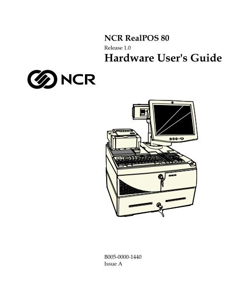
NCR <strong>RealPOS</strong> 80Release 1.0Hardware User's GuideB005-0000-1440Issue A
The product described in this book is a licensed product of NCR Corporation.NCR is a registered trademark of NCR Corporation.NCR <strong>RealPOS</strong>, NCR RealPrice, NCR RealScan, NCR EasyPoint and NCR FastLane are either registeredtrademarks or trademarks of NCR Corporation in the United States and/or other countries.It is the policy of NCR Corporation (NCR) to improve products as new technology, components, software,and firmware become available. NCR, therefore, reserves the right to change specifications without priornotice.All features, functions, and operations described herein may not be marketed by NCR in all parts of theworld. In some instances, photographs are of equipment prototypes. Therefore, before using this <strong>doc</strong>ument,consult with your NCR representative or NCR office for information that is applicable and current.To maintain the quality of our publications, we need your comments on the accuracy, clarity, organization,and value of this book.Address correspondence to:Manager, Information ProductsNCR Corporation2651 Satellite Blvd.Duluth, GA 30096Copyright © 2003By NCR CorporationDayton, Ohio U.S.A.All Rights Reserved
iSafety WarningsPrefaceAudienceThis book is written for hardware installer/service personnel, systemintegrators, and field engineers.Notice: This <strong>doc</strong>ument is NCR proprietary information and is not tobe disclosed or reproduced without consent.ServicingCaution: This product does not contain user serviceable parts.Servicing should only be performed by a qualified service technician.Fuse ReplacementCaution: For continued protection against risk of fire, replace onlywith the same type and ratings of fuse.Attention: Pour prévenir et vous protéger contre un risque de feu,remplacer la fusible avec une autre fusible de même type, seulement.Power Supply Cord Used as Disconnect MeansCaution: The power supply cord is used as the main disconnectdevice. Ensure that the socket outlet is located/installed near theequipment and is easily accessible.Attention: Le cordon d'alimentation est utilisé comme interrupteurgénéral. La prise de courant doit être située ou installée å proximité dumatériel et être facile d'accés.
iiLithium Battery WarningCaution: Danger of explosion if battery is incorrectly replaced.Replace only with the same or equivalent type as recommended by themanufacturer. The battery is battery is recyclable. At the end of itsuseful life, under various state and local laws it may be illegal todispose of this battery into the municipal waste. Contact officials forrecycling options or proper disposal.Attention: Il y a danger d'explosion s'il y a remplacement incorrect dela batterie. Remplacer uniquement avec une batterie du même type oud'un type recommandé par le constructeur. Mettre au rébut lesbatteries usagées conformément aux instructions du fabricant.Battery Disposal (Switzerland)Refer to Annex 4.10 of SR814.013 for battery disposal.IT Power SystemThis product is suitable for connection to an IT power system with aphase-to-phase voltage not exceeding 240 V.Peripheral UsageThis terminal should only be used with peripheral devices that arecertified by the appropriate safety agency for the country of installation(UL, CSA, TUV, VDE) or those which are recommended by NCRCorporation.Caution: DO NOT connect or disconnect a printer, keyboard, or anyother terminal-powered peripheral while the terminal is powered on.Doing so may result in peripheral or system damage.Environmental ConsciousnessNCR is demonstrating its concern for the environment by designing anintelligent power management system into this terminal that operatesefficiently whether the system is in a stand-alone or networkenvironment.
iiiGrounding InstructionsIn the event of a malfunction or breakdown, grounding provides apath of least resistance for electric current to reduce the risk of electricshock. This product is equipped with an electric cord having anequipment-grounding conductor and a grounding plug. The plug mustbe plugged into a matching outlet that is properly installed andgrounded in accordance with all local codes and ordinances. Do notmodify the plug provided – if it will not fit the outlet, have the properoutlet installed by a qualified electrician. Improper connection of theequipment-grounding conductor can result in a risk of electric shock.The conductor with insulation having an outer surface that is greenwith or without yellow stripes is the equipment-grounding conductor.If repair or replacement of the electric cord or plug is necessary, do notconnect the equipment-grounding conductor to a live terminal. Checkwith a qualified electrician or service personnel if the groundinginstructions are not completely understood, or if you are in doubt as towhether the product is properly grounded.Use only 3-wire extension cords that have 3-prong grounding plugsand 3-pole receptacles that accept the product’s plug. Repair or replacedamaged or worn cords immediately.
viNCR 5952 10.4-Inch DynaKey...........................................................1-23NCR 5932 Keyboards .........................................................................1-24109-Key USB Keyboard ...............................................................1-24Features .....................................................................................1-25115-Key PS/2 Big Ticket Keyboard............................................1-2668-Key PS/2 POS Keyboard........................................................1-27Features .....................................................................................1-27NCR 5972 2x20 Remote Customer Display.....................................1-31Features..........................................................................................1-31NCR 5973 2x20 International VFD Customer Display ..................1-32Features..........................................................................................1-32Printers .................................................................................................1-33NCR 7158 Printer..........................................................................1-33NCR 7162 Printer..........................................................................1-34NCR 7194 Printer..........................................................................1-34NCR 7167 Printer..........................................................................1-35NCR 7197 Printer..........................................................................1-35System Configuration Diagrams ......................................................1-36Chapter 2: Hardware InstallationIntroduction ...........................................................................................2-1Installation Restrictions .................................................................2-1Cautions...........................................................................................2-1Installing the Integration Tray ............................................................2-2Installing the Keyboard........................................................................2-3PS/2 Keyboard/Mouse Cable Connections ...............................2-5Dual Port Keyboard/Mouse Installation................................2-5Mouse Installation Restriction..................................................2-5Installing the Integrated Operator Display .......................................2-6Operator Display Cable Connections........................................2-10Installing an NCR 5964 12.1-inch Touch LCD .....................2-10
viiInstalling a 5942 12.1-Inch LCD Monitor..............................2-13Installing the Integrated Customer Display....................................2-14Installing the Transaction Printer .....................................................2-16Printer Cable Connections...........................................................2-18USB Installation........................................................................2-18RS-232 Installation w/Power from Powered USB ..............2-19Installing an NCR 5972 Remote Customer Display .......................2-20Customer Display Cable Connections.......................................2-21Installing an NCR 5973 Remote Customer Display .......................2-22Customer Display Cable Connections.......................................2-23Installing a 5953 DynaKey .................................................................2-24Installing a 5952 DynaKey .................................................................2-25Installing a Secondary CRT Display (Dual Display)......................2-26Installing the Hardware...............................................................2-26Supported Configurations ......................................................2-26Supported Configurations by Operating System ................2-27Supported Hardware Configurations ...................................2-27Installing the Displays.............................................................2-28Configuring the Software for Dual Display..............................2-29Installing an NCR 5982 5-Inch Operator Display...........................2-30Installing the PCI LCD Board (5952-K052)................................2-31Connecting the 5982 Display to the Terminal......................2-32Installing a Cash Drawer ...................................................................2-33Installing a Second Cash Drawer...........................................2-33Chapter 3: SetupIntroduction ...........................................................................................3-1Entering Setup Using a Keyboard ......................................................3-1How to Select Menu Options ..............................................................3-1Restoring Factory Settings ...................................................................3-2Special DynaKey Keypad Mode .........................................................3-2
ixNCR <strong>RealPOS</strong> 80/80c Windows XPe Operating SystemRecovery Software (LPIN: D370-0570-0100) .............................4-13Installed Software: ...................................................................4-13Software Drivers.......................................................................4-13Special Settings.........................................................................4-14Recommendation .....................................................................4-14OS Recovery from a Larger Disk Image ..........................................4-15Chapter 5: BIOS Updating ProceduresIntroduction ...........................................................................................5-1Prerequisites....................................................................................5-1Connecting an External Backpack CD-ROM Drive...................5-2Updating Procedures .....................................................................5-3BIOS Crisis Recovery............................................................................5-5Recovery Procedures......................................................................5-6Cable/Connector Pin-Out Information .............................................5-9Chapter 6: Memory DumpGeneral Memory Dump Information.................................................5-1BIOS Requirements ........................................................................5-1Disk Format.....................................................................................5-1Supported Operating Systems......................................................5-2Summary of Operating Systems ..............................................5-3Prerequisites....................................................................................5-3Windows XP/2000.....................................................................5-4Windows NT...............................................................................5-5DOS Memory Dump Specifics ............................................................5-6Dump Process Overview...............................................................5-6Restrictions and Limitations .........................................................5-6Performing the Memory Dump....................................................5-9Configuring the Terminal .........................................................5-9
xi5972 VFD Customer Display (Powered RS-232) ....................... C-75972 LCD Customer Display (Powered RS-232)....................... C-8DVI to DVI for 5964....................................................................... C-8PS/2 - RS-232 & Power for 5964.................................................. C-8Wedge Keyboard Adapter ........................................................... C-912.1-Inch LCD Aux Power Cable ................................................ C-9Cash Drawer Cables .......................................................................... C-10Dual Cash Drawer, Y-Cable....................................................... C-10Cash Drawer, Extension Cable .................................................. C-10Ethernet Communications Cable..................................................... C-10Keyboard Cables ................................................................................ C-11PS/2 Keyboard Extension .......................................................... C-11PS/2 Y-Cable................................................................................ C-11Signature Capture/Electronic Payment Terminal Cable ............. C-125945/5992 EPT (RS-232 w/Power) ........................................... C-125942 12V Power Cable................................................................. C-12IDE Cables........................................................................................... C-13IDE Interface Cable (3-Connector) ............................................ C-13IDE Interface Cable (2-Connector) ............................................ C-13Compact Flash Power Cable............................................................. C-13Power Cables ...................................................................................... C-14AC Power...................................................................................... C-14Appendix D: Memory MapDOS Considerations ............................................................................D-2Non-TAPS DOS Environment .....................................................D-3TAPS DOS Environment ..............................................................D-3
xiiRevision RecordIssue Date RemarksA Feb 2003 First issue
xiiiRadio Frequency Interference StatementsFederal Communications Commission (FCC)Information to UserThis equipment has been tested and found to comply with the limits for a Class Adigital device, pursuant to Part 15 of FCC Rules. These limits are designed to providereasonable protection against harmful interference when the equipment is operated ina commercial environment. This equipment generates, uses, and can radiate radiofrequency energy and, if not installed and used in accordance with the instructionmanual, may cause harmful interference to radio communications. Operation of thisequipment in a residential area is likely to cause interference in which case the userwill be required to correct the interference at his own expense.NCR is not responsible for any radio or television interference caused by unauthorizedmodification of this equipment or the substitution or attachment of connecting cablesand equipment other than those specified by NCR. The correction of interferencecaused by such unauthorized modification, substitution or attachment will be theresponsibility of the user. The user is cautioned that changes or modifications notexpressly approved by NCR may void the user’s authority to operate the equipment.Canadian Department of CommunicationsThis Class A digital apparatus complies with Canadian ICES-003.This digital apparatus does not exceed the Class A limits for radio noise emissionsfrom digital apparatus set out in the Radio Interference Regulations of the CanadianDepartment of Communications.Cet appareil numérique de la classe A est conforme à la norme NMB-003 du Canada.Le présent appareil numérique n'émet pas de bruits radioélectriques dépassant leslimites applicables aux appareils numériques de la classe A prescrites dans lerèglement sur le brouillage radioélectriques édicté par le ministrère desCommunications du Canada.
xivVoluntary Control Council for Interference (VCCI)International Radio Frequency Interference StatementWarning: This is a Class A product. In a domestic environment this product maycause radio interference in which case the user may be required to take adequatemeasures.
xvDeclaration of ConformityManufacturer's NameManufacturer's AddressType of EquipmentNCR CorporationModel Number Class <strong>7458</strong>Electrical Ratings (Input)NCR CorporationRetail Solutions Division – Atlanta2651 Satellite BoulevardDuluth, GA 30096-5810Information Technology Equipment100-120 V/200-240 V, 2.0 A/1.0 A, 50-60 HzNCR Corporation, 1700 South Patterson Boulevard, Dayton, OH 45459,USA, declares that the equipment specified above conforms to thereferenced EU Directives and Harmonized Standards.EU DirectiveHarmonized Standard(s)89/336/EEC (EMC) EN 55022EN 5502473/23/EEC (Low Voltage) EN 60 950NCR CorporationRetail Solutions Division — Atlanta2651 Satellite BoulevardDuluth, GA 30096-5810European Contact:International IP Counsel206 Marylebone RoadLondon, NW1 6LY, England
Chapter 1: Product OverviewIntroductionThe NCR <strong>RealPOS</strong> 80 (also referred to as NCR <strong>7458</strong>) is a powerful,retail-hardened point-of-sale terminal targeted for generalmerchandise, food and convenience store environments. It providesexceptional scalability utilizing Intel Celeron and Pentium IIIprocessors to address a range of price/performance levels andoperating system environments. The system offers superiorconnectivity for retail, with support for legacy peripheral interfaces(RS-232, PS/2, Parallel, and VGA), as well as emerging interfacestandards such as Powered USB and a DVI video interface.There are two color schemes available; Beige (G11) and CharcoalGray (CG1).Beige (G11)Charcoal Gray (CG1)20311c
1-2 Chapter 1: Product OverviewThe <strong>7458</strong> is designed with serviceability in mind to reduce costlydowntime. It incorporates the latest in serviceability features includingtool free serviceability. Specifically, the <strong>7458</strong> incorporates:• Removable hard drive – The terminal utilizes a front-sideremovable hard drive that slides easily out of the cabinetry withoutthe use of any tools, which simplifies replacement.• Slide out motherboard tray – All internal components are quicklyaccessed and replaced without the aid of tools, which significantlyreduces repair times.• The removable tray results in faster upgrading of memory, harddrive or other internal components.• In integrated configurations, the slide out motherboard trayeliminates the need to remove peripherals from the top of the unit.• Removable motherboard tray permits for easy upgrade to nextgeneration motherboards.CabinetThe cabinet is optimized to accommodate either modular or integratedconfigurations while providing expandability for future needs.Outstanding flexibility has been designed into the optional integrationtray for use with unified configurations. This integration tray supportsa variety of NCR’s most popular peripheral options.Internally, the following features are supported:• 3 PCI slots• 2 DIMM memory sockets supporting up to 512MB of PC133SDRAM• Flex disk drive (standard)• Dual hard disk drives• CD ROM drive• Compact flash memory
Chapter 1: Product Overview 1-3• Integrated battery back-up.The following table highlights the standard features and optionsavailable with the <strong>RealPOS</strong> 80 base Models:Major Model CPU<strong>7458</strong>-1110 Intel 850MHz Celeron, 128MB Memory, Flex Disk, 4RS-232, 4 Powered USB, Audio/Mic. and US PowerCord. (G11)<strong>7458</strong>-1111 Intel 850MHz Celeron, 128MB Memory, Flex Disk, 4RS-232, 4 Powered USB, Audio/Mic. and US PowerCord. (CG1)<strong>7458</strong>-1200 Intel 850MHz Celeron, 128MB Memory, Flex Disk, HardDisk, 4 RS-232, 4 Powered USB, Audio/Mic. and USPower Cords (G11)<strong>7458</strong>-1201 Intel 850MHz Celeron, 128MB Memory, Flex Disk, HardDisk, 4 RS-232, 4 Powered USB, Audio/Mic. and USPower Cords. (CG1)<strong>7458</strong>-2200 Intel 1GHz Pentium III, 256MB Memory, Flex Disk, HardDisk, 4 RS-232 4 Powered USB, Audio/Mic. And USPower Cords. (G11)<strong>7458</strong>–2201 Intel 1GHz Pentium III, 256MB Memory, Flex Disk, HardDisk, 4 RS-232 4 Powered USB, Audio/Mic. And USPower Cords. (CG1)The <strong>7458</strong> supports a broad range of industry standard operatingsystem environments including DOS, Windows NT, and Windows2000 Professional. In addition, the <strong>7458</strong> is Linux certified using certainLinux distributions.
1-4 Chapter 1: Product OverviewConfigurationsIntegrated Terminal20311a20314a
Chapter 1: Product Overview 1-5Integrated Terminal w/Cash Drawer20385a
1-6 Chapter 1: Product OverviewLeft/Right ConfigurabilityThe integrated displays and printers can be configured as desired.2038620385
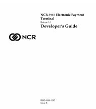
Certificate of AuthenticityACN 000 003 592Class:<strong>7458</strong>-2201S/N:36309845 Date:21 November 2002Chapter 1: Product Overview 1-7Serial Number/Model Number LabelThe serial number and model number are included on a label, which islocated on the bottom of the Electronics Box Tray, which can be seenthrough a rectangular hole in the bottom of the cabinet. If the terminalwas shipped with an Operating System pre-installed then there is alsoa Certificate of Authenticity label.Note: The serial number is repeated on the inside of the Front SecurityDoor.Class:<strong>7458</strong>-2201S/N:36309845 Date:21 November 2002NCR Corporation Atlanta, GA 30096 Made in SingaporeClass <strong>7458</strong>100-240 Vac 6.0 A 50-60 Hz This device complies with Part 15 of the FCC rules.Operation is subject to the following two conditions:Model No: xxxx(1) this device may not cause harmful interference, and(2) this device must accept any ionterference received,Serial No: 54-xxxxxxxxincluding interference that may cause indesired operation.This Class A digital apparatus complies withDate of Mfg. 04/10/03Canadian ICES-003Get Appareli numeriqe de la classe A estconformo a la normo NMB-003 ju CanadaI. T. E.E152553NO.437Windows 2000 Pro Embedded 1-2 CPUProduct Key:H95X7-83WVV-CFCWW-M4MXX7-X6XGM00019-068-654-23420347
1-8 Chapter 1: Product OverviewFeaturesProcessor BoardThe processor board has the following features:• Support for Intel Celeron processors with 66MHz or 100MHz frontside bus speeds as well as Intel Pentium III processors with133MHz front side bus speeds.• Two DIMM memory sockets (up to 512 MB of PC133 SDRAM)• Support for 3 PCI cards via Riser Card• Video Controller with VGA, SVGA and XGA graphics capability• Up to 8MB Video Memory - Unified Memory Architecture (UMA)• Two IDE ports (Ultra DMA 33/66/100 Master Mode EIDEController)• 1.44 MB Flex Disk interface• DVI-I connector (Digital Video Interface)• 15-pin D-shell connector for CRT or analog LCD• Ethernet 10/100baseT LAN• Four External RS-232 ports (two powered, one selectable, onenon-powered)• One internal TTL RS-232 port for integrated UPS interface• 25-pin D-shell Parallel connector• PS/2 keyboard/mouse connector (requires external Y-cable to useboth)• AC-97 Audio Interface• APM 1.2• Real-Time Clock/Calendar 256-byte CMOS• Supports 4 Powered USB ports via daughter card• Supports internal UPS battery back-up
Chapter 1: Product Overview 1-94-Port USB Daughter CardATX Riser Card• Four Powered USB ports− 12V (3)− 24V (1)• AC-97 CODEC• Amplified stereo output jack (5W max. per channel)• Microphone input• Connector for accepting CD-ROM audio (music compact disc)• Ports C & B are controlled by the USB controller at Bus 0, Device 7,Function 2• Ports A & 24V are controlled by the USB controller at Bus 0, Device7, Function 3Note: The USB controller can be disabled in BIOS Setup under theAdvanced menu, in the OnChip Multi-function Device menu. It isidentified as OnChip USB 2 Device:.• An ATX style PCI Riser Card provides three PCI expansion slots−33 MHz, 5V, 32 bitNote: Maximum length for PCI cards is 150mm (5.9 in.)
1-10 Chapter 1: Product OverviewFront Control PanelThe control panel assembly includes the following features:• ON/OFF switch• Power On LED− Steady Green: All voltages good− Flashing green: Suspend mode− Off: Terminal off or bad voltages• Hard Drive Activity LED− Orange: Lit indicates Hard drive activity• LAN Link LED− Green: Lit indicates good LAN connection to hub.• Cabinet Fan power connection− 12V and Ground− 3 position• Speaker connection− 2 position• Reset switch− Hidden momentary push button switchStorage Media• 3.5 in. Flex Disk Drive• 3.5 in. Hard Disk Drives (2)− Front-Accessible Removable Drive− 2 nd Internal Hard Drive• Slimline CD-ROM (bootable)• 256 MB Compact Flash (through IDE interface)
Chapter 1: Product Overview 1-11Power Supply• 300 W Output power• Support for optional Internal UPS Battery Back-upOperating Systems• DOS 6.22• Windows NT Workstation• Windows 2000 Professional• Windows XPe• Windows EP (certified)• Linux (certified)UPSThe Uninterrupted Power Supply (UPS) in the <strong>7458</strong> is designed tosupport the terminal in the event AC Power is lost. This permitssufficient time for the terminal to finish the current transaction andperform a logical shutdown of the Operating System, which helps toguard against disk corruption caused by an illogical power OFF.The power supply senses the loss of AC voltage and switches tobattery support.The Power Supply provides limited filtering of low frequency noiseand minor AC line variations, however, it does not protect the terminalfrom excessive AC Power line spikes such as some external UPS unitsprovide.
1-12 Chapter 1: Product OverviewPower ManagementPower management is implemented on the <strong>7458</strong> using the ACPI 1.1Specification 1.1. In order to accomplish this, the processor board isequipped with ACPI BIOS.The BIOS supports the ACPI 1.1 specification. This permits theterminal to go to a low power state during some level of inactivity.With ACPI, the operating system has some control over the powermanagement by going into suspend, standby, or hibernate (depending onthe Operating System). The S0, S1, S4, and S5 states are implemented.For the detail of the ACPI, refer to ACPI Specification 2.0b. Not all Entryand Exit points are available at all times. Availability is based on ACPIstates.Notes:• When the LAN cable is connected a WakeOnLink notification is sentto the operating systems, causing the terminal to come out of a lowpower state such as hibernation under Windows 2000. This issimilar to the WakeOnLan feature.• On terminals running BIOS 3.0.0.0 or greater, Wake on Alarm is notsupported from the "off" state. This because the ACPI powermanagement in the BIOS does not allow the Timer/Alarm to wakethe system. Wake on LAN is supported. Similar functionality can beimplemented from the server by sending a LAN wakeup message.• Wake on Alarm from Window NT is not supported.• UPS devices must be enabled in Windows for Wake from Standby tofunction. This is set in at:Start Control Panel System Hardware Tab DeviceManager [USB device] Properties.There is a check box to enable the function under the USB tab.
Chapter 1: Product Overview 1-13Definitions of the states involved• Mechanical Off: System is not working. No AC power isconnected to the system. Operational parameters are nit saved.System resets and initializes when transitioning to the Full OnState.Entry: a) Remove power from unit.Exit:b) Attempt to enter Soft Off while running off UPS.Connect power to unit. (move to Soft Off or Full On or APMEnabled)• Soft Off: AC Power is connected to the system. Only the 5Vstandby and 3.3V standby voltages are present within the machine.Note: Soft Off is not supported by the UPS. The UPS doesnotsupport the suspend voltages in this state. Therefore, the unit isreally in Mechanical Off when there is no AC power and anattempt is made to enter Soft Off while running off the UPS.Entry: a) Connect power to unit.Exit:b) Turn off unit via power button. Power button can beconfigured for either instant off or for off after beingpressed for longer than four seconds.c) Unit turned off via software controla) Press power buttonb) Wake On LANc) Wake ON Ringd) Wake On Alarme) Remove AC
1-14 Chapter 1: Product Overview• Full On: System is working and not power managed (APMDisabled)Entry: a) Press power button.Exit:b) Wake On LANc) Wake On Ringd) Wake On Alarma) Turn off unit via power button. Power button can beconfigured for either instant off or for off after beingpressed for longer than four seconds.b) Unit turned off via software controlc) Remove AC• APM Enabled: System is working and not power managedEntry: a) Press power buttonExit:b) Wake On LANc) Wake On Ringd) Wake On Alarme) Wake on keyboard, mouse, or touch activityf) Wake on USB activitya) Turn off unit via power button. Power button can beconfigured for either instant off or for off after beingpressed for longer than four seconds.b) Unit turned off via software controlc) Disable APMc) Remove AC
Chapter 1: Product Overview 1-15• APM Standby• System is in a low power state with some power savings• Most devices are in a low power mode.• The CPU clock is slowed or stopped.• Operational parameters are retained.• System returns quickly to the APM Enabled State.• The Resume Timer event must return the system to the APMEnabled state.• User activity may be required to return the system to the APMEnabled State.• The operating system is notified after the system transitions tothe APM Enabled State.• Prior operation resumes after returning to the APM Enabledstate.• Interrupts must still be processed normally. This may requirewaking up the CPU temporarily if it was stopped.• The CPU may be stopped again when the APM Driver calls theCPU Idle function.Some (not all) specific device states:• Hard Drive: Standby (motor not spinning, interface bufferactive)• Display: CRT – Suspend (No image on screen, LCD – Off• Video Controller: Standby• Chipset: StandbyEntry: a) Programmable timeoutb) Under software controlExit:a) Wake On LANc) Wake ON Ringd) Wake On Alarme) Wake on keyboard, mouse, or touch activityf) Wake on USB activityg) Remove AC
1-16 Chapter 1: Product Overview• APM Suspend: System is in a low power state with maximumpower savings. Most power managed devices are not powered.The CPU clock is stopped. The CPU core is in its minimumpowered state. Operational parameters are saved to be restoredlater when resuming. System takes a relatively long time to returnto the APM Enabled state. The Resume Timer event must be on ofthe wakeup events. The operating system is notified after thesystem transitions to the APM Enabled state. Prior operationresumes after returning the APM Enabled state.Some (not all) specific device states:• Hard Drive: Sleep (motor not spinning, interface bufferinactive)• Display: CRT – Off, LCD – Off• Video Controller: Suspend• Chipset: SuspendEntry: a) Programmable timeoutb) Under software controlExit:a) Wake On LANc) Wake ON Ringd) Wake On Alarme) Wake on keyboard, mouse, or touch activityf) Wake on USB activityg) Remove AC
Chapter 1: Product Overview 1-17Operator Displays5964 12.1-Inch Touch Screen19429The 5964 is designed for touch-based applications and features a highbrightness12.1-Inch Active Matrix Color LCD with SVGA resolution.The 5964 features a 5-wire Resistive Touch Screen, integrated MSR,Digital Video Interface (DVI), table top mount with tilt and swivel (orcan be integrated on the terminal), and convenient connections for anexternal keyboard and hand held scanner.FeaturesResistive Touch ScreenRetail Hardened12.1-Inch Active MatrixLCDTouch overlay uses 5-wire resistive technology forease of use and long reliability.Resistive technology allows users to operate thetouch screen with a gloved hand, stylus, etc.Touch screen surface contains an anti-glare, spillproofand hardening coatingDual backlight color LCD display offers exceptionalbrightness (300 nits max.) and viewability.
1-18 Chapter 1: Product OverviewBrightness ControlWide Viewing AngleSVGA ResolutionPS/2 KeyboardConnectorScanner ConnectorTone SpeakerDVI Video InterfaceRS-232 Touch InterfaceWedge ControllerTerminal PoweredMSR OptionTilt / SwivelThe LCD is factory set to run at full brightness.Users can select reduced brightness through a useradjustable hardware switch below the right frontbezel (high/low brightness).Horizontal viewing angle of –60° to +60° (right toleft), vertical –50° to +50° (bottom to top)High resolution (800 x 600) supports the latestgraphical and multimedia applicationsA convenient PS/2 connector supports a nonwedgePC-style keyboard for alpha entry anddiagnosticsRJ-45 interface provides 5 V power andcommunication for the NCR RS-232 hand-heldscannerSounds error tones & audible feedback duringoperator input - controlled by TAPS/OPOScommandsIndustry standard DVI (Digital Video Interface) forconnection to DVI-I connector on <strong>7458</strong><strong>7458</strong> Powered RS-232 connector provides powerand touch interface for NCR 5964 displayPasses data (MSR, scanner, keyboard) to hostterminal through PS/2 data stream via Y-cableNo additional power cord or power supply isrequired simplifying cable managementIntegrated 3-track ISO MSRThe remote table top pedestal mount supports tiltand swivel to adjust display to optimum angle
Chapter 1: Product Overview 1-195942 12.1-INCH Color LCD19809The 5942 12.1-Inch LCD is designed for customers who desire a colordisplay and prefer the small footprint and ergonomic packaging ofLCD technology versus traditional CRT’s. Depending on thecustomer’s requirements, this LCD display can be used either as anoperator display or a customer information display (CID). The 5942Display features a 12.1-Inch Active Matrix Color LCD with support forSVGA and XGA resolution.The 5942 can be integrated on the terminal or installed on a remotemount.
1-20 Chapter 1: Product Overview7452-K309/K404 9-Inch Monochrome CRTThe 9-Inch CRT can be integrated on the terminal or installed on aremote mount.7452-K309 7452-K40419742a7452-K419 15-Inch Color CRTThe 15-Inch CRT can be integrated on the terminal or installed on aremote mount.Note: The 15-Inch display is too large for the Swivel Arm. Forintegrated configurations it is placed on the Large Peripheral ExtensionDeck.19743
Chapter 1: Product Overview 1-21NCR 5982 5-Inch LCD DisplayThe 5982 LCD Display is a terminal-powered monochrome 5-InchVGA LCD.19744
1-22 Chapter 1: Product OverviewNCR 5953 12.1-Inch DynaKeyThe 5953 DynaKey is a Point-of-Sale (POS) keyboard with a built-in12.1-Inch SVGA flat panel Liquid Crystal Display (LCD). The 5953features an active matrix (TFT) color LCD. A Touch Screen is alsoavailable as an option.Unique to the 5953 DynaKey are a set of DynaKeys located beside theLCD. These keys change function depending on the softwareapplication appearing on the LCD. Also unique are two up/downscroll keys. The keypad module contains configurable key matrix,DynaKeys, and scroll keys.The 5953 can be integrated on the terminal or installed on a remotemount.Note: The 5953 requires a PCI SVGA LCD card.Additional features include:• Keylock• 3-track ISO Magnetic Stripe Reader (MSR) or JIS MSR (Japan)• Speaker (separate from the PC speaker)• Multi-color power status LED• Connectors for a decoded RS-232 scanner and a PC keyboard17089
Chapter 1: Product Overview 1-23NCR 5952 10.4-Inch DynaKeyThe 5952 Wedge DynaKey is a point-of-sale keyboard with a VGA flatpanel Liquid Crystal Display (LCD). Unique to the 5952 DynaKey is aset of dynamic keys located beside the LCD. These keys change functiondepending on the software application appearing on the LCD. Alsounique are two up/down scroll keys. Additional features include:• Keylock• 3-track ISO Magnetic Stripe Reader (MSR)• Speaker• Connectors for a PC keyboard• Connector for RS-232 scanner• Terminal-powered20447
1-24 Chapter 1: Product OverviewNCR 5932 Keyboards109-Key USB KeyboardThere are three models of the 5932 Keyboard:• 109-Key USB Keyboard• 115-Key Big Ticket Keyboard (PS/2 interface)• 68-Key POS Keyboard (PS/2 interface)KeylockMSRThe 109-key USB keyboard is a multifunction keyboard that is twokeyboards built into one.The keyboard consists of two major sections:• 38-key POS keyboard• Industry-standard alphanumeric PC keyboard19586The keyboard contains the key matrix and other POS-specific functionssuch as Keylock, speaker, system status indicator, and magnetic stripereader (MSR). This 5932 keyboard also has a USB port to connect aScanner or other USB device.
Chapter 1: Product Overview 1-25FeaturesThe NCR 5932 USB Keyboard supports the following features:• Keylock• Speaker• Magnetic Stripe Reader (MSR)• Keyboard Status LEDsKeylockThe USB keyboard has a four-position Keylock. You can rotate theKeylock between specific positions by use of three keys. The positionsare explained in the following table.Abbreviation Position DescriptionEx Exception Used by the customer or servicerepresentative to perform lowlevel programming such asworkstation diagnostics,configuring the workstation, orloading the workstation.L Locked Used to lock keyboard input toprohibit use of normal functions.R Register Used when performing normalretail mode functions.S Supervisor Used by the supervisor toprovide highest level ofworkstation control in cases suchas refunds and running totals.SpeakerThe programmable speaker is capable of generating key clicks anderror tones.
1-26 Chapter 1: Product OverviewMSRThe MSR is an optional feature that provides support for readingmagnetically coded data cards. The keyboards support two differenttypes of MSR:• ISO Tracks 1, 2, and 3• JIS-II and ISO Track 2Keyboard Status LEDsThe keyboard has three status LED’s:• Num Lock• Caps Lock• Scroll LockThese features are used to provide the present state of the keyboard.The indicators are single color (Green) LED’s. When the system is off,no LED’s are illuminated.115-Key PS/2 Big Ticket KeyboardStatusIndicatorKeylockMSR19745
Chapter 1: Product Overview 1-2768-Key PS/2 POS KeyboardKeylockStatusIndicatorMSR19746FeaturesThe 5932 PS/2 Keyboards include the following features:• Keylock• Speaker• System Status Indicator LED• Magnetic Stripe Reader (MSR)• External Decoded Scanner Connector• Special PC Setup mode on the 68-key keyboardThe operations of the user-programmable speaker, Magnetic StripeReader (MSR), keylock, and scanner connector are handled by theWedge controller. Please refer to the Wedge Software User's Guide(BD20-1368-A) for detailed information about interfacing andconfiguring these devices.
1-28 Chapter 1: Product OverviewKeylockThe Big Ticket and 68-key keyboards have a four-position keylockswitch. The positions are explained in the following table.Abréviation Position DescriptionEx Exception Used by the customer or servicerepresentative to perform low-levelprogramming such as terminaldiagnostics, configuring the terminal,or loading the terminal.L Locked Used to lock keyboard input toprohibit use of normal functions.R Register Used when performing normal retailmode functions.SSupervisor Used by supervisor to provide highestlevel of terminal control in cases suchas refunds and running totals.SpeakerA programmable speaker generates key clicks and error tones.BuzzerThe buzzer is an internal on board Buzzer.System Status Indicator LEDThe system status indicator is a two-color LED. The green colorindicates the keyboard is powered. Red indicates an error condition.When the system is off, the LED is extinguished.When the 68-key keyboard is in the special "PC setup" mode, the LEDflashes red/green.
Chapter 1: Product Overview 1-29The status and condition indicated by the LED are shown as follows:StatusGreenRedFlashing red/greenOffConditionPower onWedge controller reporting an error conditionKeypad of 68-key keyboard in "PC Setup" mode(See special keypad mode on next page)System offNote: For more information about the Wedge controller, refer toWedge Software User's Guide (BST0-1368-B).MSR (Magnetic Stripe Reader)The MSR is an optional feature that provides support for readingmagnetically coded data cards. The keyboards support two differenttypes of MSR:• ISO Tracks 1, 2, and 3• JIS-II and ISO Track 2 (Big Ticket and full-featured 68-keykeyboards only)Note: MSR signals are routed to the Wedge controller and passed intothe system keyboard data stream. For more information about theWedge controller, refer to Wedge Software User's Guide (BD20-1368-A)External Decoded Scanner ConnectorA decoded RS-232 input device that only requires TXD, RXD, CTS andRTS, such as a bar-code scanner, can be connected to the keyboard. RS-232 signals are routed to the Wedge controller and passed into thesystem keyboard data stream. The connector provides +5V to powerthe scanner. For more information about the Wedge controller, refer toWedge Software User's Guide (BD20-1368-A).
1-30 Chapter 1: Product OverviewSpecial "PC Setup" Keypad Layout for 68-key KeyboardOn power-up, the operator can switch the 68-key keyboard into analternate keypad layout that can be used with many PC BIOS setupand configuration routines. The alternate layout contains keys such asESC, TAB, END, "+", "-" and arrow keys which are not available in thenormal keypad layout. The alternate layout allows the operator toconfigure a PC with the 68-key keyboard.
Chapter 1: Product Overview 1-31NCR 5972 2x20 Remote Customer DisplayDesktop Model16-Inch Post20448Features• RS-23 Interface• Socket for 32K of PROM for additional character sets (5972-1000VFD).• 7 x 9 pixel characters (5972-1000 VFD); 5 x 8 pixel characters on5972-2000 LCD• Diagnostics• Character sets:Code Page 850 (International)Katakana (except 5972-2000)Code Page 866 (Cyrillic) (except 5972-2000)
1-32 Chapter 1: Product OverviewNCR 5973 2x20 International VFD Customer DisplayDesktop Model16-Inch Post20448Features• 256x64 dots graphic VFD• Micro-controller• Flash ROM• Display driver circuitry• Communication/power connector• Power converter circuitry• Communication drivers• Bi-directional parallel interface support
Chapter 1: Product Overview 1-33PrintersNCR 7158 PrinterThe NCR 7158 Printer is extremely fast, quiet, and reliable point-of-saledevice. It consists of two specialized printers in one compact package: athermal printer on top that prints receipts, and an impact slip printer infront to print on forms and checks that you insert. The printer featuresa dual interface, so it can connect to the host terminal either through aUSB interface or RS-232. It can receive its power from an externalpower supply or through the 24V Powered USB port on the terminal. Italso has a connector for cash drawers.Power SupplyAC Adapter Cable17304a
1-34 Chapter 1: Product OverviewNCR 7162 PrinterThe NCR 7162 is a dot matrix printer that provides up to 40 columnsreceipt and journal, and up to 88 columns of slip print. The printer’sfeatures include paper low sensors, slip-out detectors, automatic papercutting, and two cash drawer kick out connectors. It has an RS-232 datainterface. It can receive its power from an external power supply orthrough the 24V Powered USB port on the terminal. It also has aconnector for cash drawers.Power SupplyAC Adapter Cable15220aNCR 7194 PrinterThe NCR 7194 Printer is a high speed, high-resolution printer, capableof both text and graphics printing. It offers direct thermal printing in areceipt station. The printer features a dual interface, so it can connectto the host terminal either through a USB interface or RS-232. It canreceive its power from an external power supply or through the 24VPowered USB port on the terminal. It also has a connector for cashdrawers.16437a
Chapter 1: Product Overview 1-35NCR 7167 PrinterThe NCR 7167 Printer is a fast, quiet, relatively small and very reliablemulti-function printer. It prints receipts, validates and prints checks,and prints on a variety of single or multiple part forms. There is notjournal as it is kept electronically by the host terminal. The printer canconnect through a USB port or a serial port. It can receive power from apower supply or through a USB+ power cable.Power SupplyAC Adapter Cable19711aNCR 7197 PrinterThe NCR 7197 Printer is a fast, quiet, relatively small and very reliablemulti-function printer. It prints receipts and two-color printing. Theprinter can connect through a USB port or a serial port. It can receivepower from a power supply or through a USB+ power cable.Power SupplyAC Adapter Cable19712a
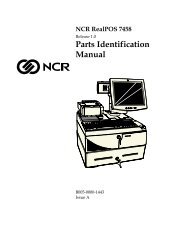
1-36 Chapter 1: Product OverviewSystem Configuration Diagrams7837 78927837 7892 5972/5973CRT5952/5953DynakeyHand-HeldScanners(Wedge)5964Touch ScreenHand-HeldScanners(Wedge)5942PS/2 KeyboardPS/2 Keyboard7167719771967158PowerPCI LCD CardUSBUSBDaughterCardDVIRS-232(Powered)VGA AC5932 USBAudio OutMicMotherboardLAN2nd Drawer (Y-Cable)Parallel2182Power(Printers)USB2189PS/25932 Big Ticket5932 64-KeyPS/2RS-232RS-232(Powered)RS-232 PeripheralsRS-232 Peripherals (Powered)7875715871677197719671625992594578827892 783720433
Chapter 1: Product Overview 1-37
Chapter 2: Hardware InstallationIntroductionInstallation RestrictionsCautionsThis chapter explains how to install the <strong>7458</strong> hardware, including outof-boxinstallation and how to install the optional peripheral devices.The <strong>7458</strong> is designed with a great deal of flexibility of how to configurethe integrated peripherals. The displays and printers can be located oneither side of the Integration Tray. Filler plates are used where thereare no peripherals present.The <strong>7458</strong> is very flexible in how it can be installed. A typicalconfiguration is discussed in this <strong>doc</strong>ument. Your configuration mayrequire adjustments to the procedures.• Before installing the <strong>7458</strong>, read and follow the guidelines in the<strong>RealPOS</strong> 80 Site Preparation (B005-0000-1360) and the NCRWorkstation and Peripheral AC Wiring Guide (BST0-2115-53.• Install the <strong>7458</strong> near an electrical outlet that is easily accessible. Usethe power cord as a power disconnect device.• Do not permit any object to rest on the power cord. Do not locatethe <strong>7458</strong> where the power cord can be walked on.• Use a grounding strap or touch a grounded metal object todischarge any static electricity from your body before servicing the<strong>7458</strong>.• This unit contains hazardous voltages and should only be servicedby qualified service personnel.• Do not connect or disconnect the transaction printer while theterminal is on. This can result in system or printer damage.
2-2 Chapter 2: Hardware InstallationInstalling the Integration Tray1. Unpack the terminal in the desired location.2. Install the Integration Tray.Note: The Integration Tray can be mounted on top of the <strong>7458</strong>terminal, on a 2189-8xxx Cash Drawer or on a counter top. Wheninstalling on a counter top use the appropriate screws.3. Align the Sheet Metal Undercarriage screw holes with the screwholes in the top of the Electronics Box.4. Align the Integration Tray Enclosure screw holes with the same.5. Secure the assembly with screws (8).Integration Tray EnclosureSheet Metal UndercarriageElectronics Box20389
Chapter 2: Hardware Installation 2-3Installing the KeyboardNCR 5932 Big Ticket Keyboard Only: The NCR Big Ticket Keyboardsare slightly thinner than the other retail keyboards and require rubberfeet below them to provide a flush cabinet fit.1. Install the adhesive-backed Rubber Feet (2) in the Keyboard well inthe Integrated Tray.Rubber Feet38 mm(1.5 in.)38 mm(1.5 in.)90 mm(3.5 in.)20427
2-4 Chapter 2: Hardware Installation2. Route the Keyboard Cable as shown below3. Install the keyboard in the Integration Tray4. NCR 5932 68-Key Keyboard Only: Install the Retail AccessoryTray.Big Ticket KeyboardRetail AccessoryTray68-Key Keyboard20398
Chapter 2: Hardware Installation 2-5PS/2 Keyboard/Mouse Cable ConnectionsPS/2 keyboards and mice are supported through a single PS/2connector. Keyboards can be plugged directly into the PS/2 connector.If PS/2 mouse is used it requires a Y-cable, whether or not a keyboardis used.Note: PS/2 Retail keyboards cannot be used in configurations withWedge type DynaKeys or Touchscreen displays. However, standard PCkeyboards can be used with these devices.MicAudioOutUse the Y-Cable to connect botha keyboard and mouse to the PS/2connector.497-0406056 - 1.8 m(1416-C281-0018)PS/2Mouse requires the Y-Cablewhether or not a keyboardis installed.Keyboard can be connected directlyto the terminal PS/2 connector.20402Dual Port Keyboard/Mouse InstallationThe <strong>7458</strong> supports both PS/2 and dual port (PS/2 - USB) keyboards. Adual port keyboard or mouse can be connected to either the PS/2connector or to a USB connector using an adapter cable.Mouse Installation RestrictionThe mouse and UPS share the same IRQ. Therefore, if a mouse isinstalled, it must be enabled in the BIOS and the UPS must be movedto another available IRQ, or disabled if not being used.
2-6 Chapter 2: Hardware InstallationInstalling the Integrated Operator Display1. Install the Operator Display Arm on the Sheet Metal Undercarriagewith screws (4).Note: There are variations in the Operator Display Arm because ofthe different types of displays that are supported. Some haveadditional parts to mount the display and some include the displayas well. The CRT mount is shown in this section but all are installedin a similar manner.Operator Display Arm20390
Chapter 2: Hardware Installation 2-7The Operator Display Arm can be installed in four possiblelocationsAlternate PositionsHole Pattern forDisplay PostSheet Metal Undercarriage(Top View)Note: When there is no Customer Display the recommendedlocation for the Operator Display is the back position, thusminimizing the overhang of the display.20393
2-8 Chapter 2: Hardware Installation2. Install the Customer Display Base with screws (4). Install the postbehind or in front of the Operator Display Arm.Note: A Filler Cap is available when there is no Customer Display.Filler Cap for No CustomerDisplay ConfigurationCustomer Display Base20395
Chapter 2: Hardware Installation 2-96. Install the Operator Display.a. Route the display cables down through the Operator DisplayArm and out the back of the cabinet.b. Insert the display into the Operator Display Arm.Note: The NCR 5953 DynaKey, NCR 5942 LCD Display, and NCR5964 Touch LCD are pre-installed on the Display Arm.20503
2-10 Chapter 2: Hardware InstallationOperator Display Cable ConnectionsInstalling an NCR 5964 12.1-inch Touch LCDThe NCR 5964 can be integrated in the terminal or it can be connectedas a remote device.Note: A PC keyboard is required to configure a 5964 12.1-inch TouchLCD.19429The following illustrations show the cable connections for the 5964 andthe <strong>7458</strong>. There are two cables required.• DVI Cable – provides the video interface to the 5964• RS-232 Y-Cable – provides a serial interface and power to the 5964.It also connects the 5964 PS/2 keyboard connector to the terminal,which provides an interface for the wedge controller (MSR, PS/2Keyboard, Scanner, Tone Speaker).
Chapter 2: Hardware Installation 2-11DVI Cable ConnectionsConnect the cable to the DVI Connector on the 5964 display and <strong>7458</strong>terminal.MicAudioOutDVI497-0422831 - 1.0 m(1416-C723-0010)DVI497-0422832 - 4.0 m(1416-C723-0040)20403
2-12 Chapter 2: Hardware InstallationRS-232 Cable Connections1. Connect the Y-cable to one of the Powered RS-232 ports and to thePS/2 connector on the <strong>7458</strong> terminal.2. Connect the other end of the Y-Cable to the RS-232 connector onthe 5964 display.MicAudioOutPowered RS-232 Ports(A, D, or C)PS/2RS-232497-0422833 - 1m(1416-C725-0010)497-04228324 - 4m(1416-C725-0040)20404For more information refer to the NCR 5964 12.1-Inch Touch LCD User'sGuide (B005-0000-1324)
Chapter 2: Hardware Installation 2-13Installing a 5942 12.1-Inch LCD MonitorThe NCR 5942 can be integrated in the terminal or it can be connectedas a remote device. It is connected through the VGA connector andreceives power from a DC power supply.MicAudioOutVGAVGAPowerAC OutletPower Supply204081. Connect the LCD Cable to the VGA connectors on both the 5942monitor and <strong>7458</strong> terminal.2. Connect the DC Power Supply to the DC Power connector on the5942 and to a standard AC outlet.For more information refer to the NCR 5942 12.1-Inch LCD MonitorUser's Guide (B005-0000-1394)
2-14 Chapter 2: Hardware InstallationInstalling the Integrated Customer Display1. Route the display cables down through the Customer Display Baseand out the back of the cabinet.2. Insert the display into the Customer Display Base.2 x 20 Customer Display20400
Chapter 2: Hardware Installation 2-153. Install the Cable Access Covers.Cable Access Cover20401
2-16 Chapter 2: Hardware InstallationInstalling the Transaction PrinterThe NCR 7167 and NCR 7197 printers can be integrated in the terminalor they can be connected as remote devices. Other printers areavailable as remote devices only.Integrated Printer Only:1. Install the Printer Support Wedge.Install the adhesive-backed Rubber Feet (4) on the Printer SupportWedge.Rubber Foot (4) Slot (4)25 mm(1.0 in.)38 mm(1.5 in.)20426Install the Wedge on the Sheet Metal Undercarriage. There are slots (4)on the bottom of the Wedge that hook into hooks on the Sheet MetalUndercarriage. Secure the Wedge with a screw.
Chapter 2: Hardware Installation 2-172. Route the printer cable out the back of the terminal and set theprinter on the Printer Support Wedge.NCR 7167 Only: Install the Filler Plate for the Printer Well (if theprinter does not have a Slip Tray), route the cable out the back ofthe terminal, and set the printer in the cabinet.NCR 7197 Only: Install the 7197 Printer Skirt, route the cable outthe back of the terminal, and set the printer in the cabinet.7197 Printer7167 Printer7197 PrinterSkirtFiller Plate forPrinter WellPrinter Support WedgePrinter SupportWedge20396
2-18 Chapter 2: Hardware InstallationPrinter Cable ConnectionsThe printers can connect through a USB connector or an RS-232connector. It receives power through a Powered USB power cable.Interfaces SupportedPrinter USB RS-2327158 √ √7162 √7167 √ √7194 √ √7197 √ √USB InstallationConnect the Powered USB Printer Interface Cable to the USB Connectorand Power Connector on the printer and to the 24 V Powered USBConnector on the terminal.MicAudioOut24V USBUSBPower497-0418587 - 1 m(1416-C640-0010)497-0418588 - 4 m(1416-C640-0040)20406
Chapter 2: Hardware Installation 2-19RS-232 Installation w/Power from Powered USB1. Connect the RS-232 Printer Interface Cable to the RS-232 Connectoron the printer and to an RS-232 Connector on the terminal.2. Connect the Printer Power Cable to the Power Connector on theprinter and to the 24 V Powered USB Connector on the terminal.MicAudioOutRS-232/B (Non-powered)497-0422292 - 4 m(1416-C712-0040)RS-232Power9-Pin to 25-Pin (7162)497-0407427 - 1.0 m(1416-C337-0010)497-0407429 - 4 m(1416-C337-0040)497-0407430 - 15.2 m(1416-C337-0152)9-Pin to 9-Pin497-0408349 - 0.7 m(1416-C266-0007)497-0407943 - 4 m(1416-C266-0040)497-0409379 - 15 m(1416-C266-0150)20407
2-20 Chapter 2: Hardware InstallationInstalling an NCR 5972 Remote Customer DisplayThere are two models of the NCR 5972 Remote Customer Display:• 5972-1000 Vacuum Fluorescent Display (VFD)• 5972-2000 Liquid Crystal Display (LCD)Table Top Model5972-1000 (VFD) 5972-2000 (LCD)19749Tall-Post Table Top Model5972-1000 (VFD) 5972-2000 (LCD)19750
Chapter 2: Hardware Installation 2-211. Locate the Display Mount within 4 meters (13 ft.) of the hostterminal.2. Determine if the cable should be routed down through themounting surface or if it should be run on top of the surface. Drill ahole if necessary.3. High-Post Mount: If you are installing High-Post model secure theMounting Plate with screws (4) that are provided.Mounting Plate4.06 mm (0.160 in.) Diameter7.6 cm(3.0 in.)14622Customer Display Cable Connections1. Connect the Display Cable to a powered RS-232 connector on theterminal.MicAudioOutPowered RS-232 Ports(A, D, or C)20405
2-22 Chapter 2: Hardware InstallationInstalling an NCR 5973 Remote Customer DisplayDesktop Model16-Inch Post204481. Locate the Display Mount within 4 meters (13 ft.) of the hostterminal.2. Determine if the cable should be routed down through themounting surface or if it should be run on top of the surface. Drill ahole if necessary.
Chapter 2: Hardware Installation 2-233. High-Post Mount: If you are installing High-Post model secure theMounting Plate with screws (4) that are provided.Mounting Plate4.06 mm (0.160 in.) Diameter7.6 cm(3.0 in.)14622Customer Display Cable ConnectionsConnect the Display Cable to the Parallel connector on the terminal.MicAudioOutPowered RS-232 Ports(A, D, or C)20405
2-24 Chapter 2: Hardware InstallationInstalling a 5953 DynaKeyThe 5953 DynaKey is a combined display and keyboard device. It canbe installed in the following configurations:• Integrated in the <strong>7458</strong>• 5953-F022 Remote Table Top Mount• 7401-K533 Wall Mount• 5952-K024 Checkstand Mount w/Base• 5953-K023 Checkstand MountThere are two types of interface models of the 5953 DynaKey. Forinstallation information for each, refer to their respective User Guides.• NCR <strong>RealPOS</strong> 5953 USB DynaKey User's Guide (B005-0000-1457)• NCR <strong>RealPOS</strong> 5953 PS/2 DynaKey User's Guide (B005-0000-1161)17089
Chapter 2: Hardware Installation 2-25Installing a 5952 DynaKey14135The 5952 Wedge DynaKey is a combined display and keyboard device.It can be installed in the following configurations:• Integrated in the <strong>7458</strong>• 5953-K032 Remote Table Top Mount• 5964-K032 Checkstand MountFor installation information refer to the NCR 5953 Wedge DynaKeyUser's Guide (BD20-1370-A)
2-26 Chapter 2: Hardware InstallationInstalling a Secondary CRT Display (Dual Display)The <strong>7458</strong> supports a dual display configuration, consisting of anycombination of the following display devices:• NCR 5953 DynaKey• NCR 5942 LCD Monitor• NCR 5964 Touch LCD• 7452-K419 15-Inch Color CRT• 7452-K404 9-Inch Mono CRT• 7452-K309 9-Inch Mono CRTInstalling the HardwareThe NCR 7456 requires either an ATI or C&T PCI card to support dualdisplay/multi-monitor.Supported ConfigurationsConfiguration ID Operator Display Customer DisplayA K593-K152 SVGA PCI LCDAdapter card(69000 chip)VIA SVGA LCD/CRT orDVI LCD (Motherboard)(VIA VT8601)BC5952-K052 VGA LCDAdapter card(65550 chip)VIA SVGA LCD/CRT orDVI LCD (Mother board)(VIA VT8601)VIA SVGA LCD/CRT orDVI LCD (Motherboard)(VIA VT8601)7456-K350 PCI VGAAdapter Card(ATI Rage XL)
Chapter 2: Hardware Installation 2-27Supported Configurations by Operating SystemOperating SystemDOSWindows 98Win NT 4.0Windows 2000Windows XPeLinuxWindows CEDual Display Configuration SupportedA, BNot supportedNot supportedA, B, CA, B, CCNot supportedSupported Hardware ConfigurationsThe following dual display combinations are supported (based on theConfiguration IDs in the above tables).Operator DisplayCustomer DisplayConfigurationIDABCDisplay Model Connected to Display Model Connected to5953 12.1-In.DynaKey (PS/2)5952 10.4-In.DynaKey (PS/2)15-In. Color CRT(7452-K419)Or9-In. Mono CRT(7452-K404/K309)5953-K152 SVGAAdapter(69000 chip)5952-K052 VGAAdapter(65550 chip)VGA connectoron Motherboard5942 12.1-In. ColorLCD or15-In. Color CRT(7452-K419)5942 12.1-In. ColorLCD or15-In. Color CRT(7452-K419)15-In. Color CRT(7452-K419)or9-In. Mono CRT(7452-K404/K309)VGA connector onMotherboardVGA connector onMotherboard7456-K350 VGAAdapter(ATI Rage XL)
2-28 Chapter 2: Hardware InstallationConfigurationIDCCCOperator DisplayCustomer DisplayDisplay Model Connected to Display Model Connected to5942 12.1-In. ColorLCD5964 12.1-In.Touchscreen LCD5953 12.1-In.USB/DVI DynaKeyVGA connectoron MotherboardDVI connector onMotherboardDVI connector onMotherboard15-In. Color CRT(7452-K419)or9-In. Mono CRT(7452-K404/K309)15-In. Color CRT(7452-K419)or9-In. Mono CRT(7452-K404/K309)15-In. Color CRT(7452-K419)or9-In. Mono CRT(7452-K404/K309)7456-K350 VGAAdapter(ATI Rage XL)7456-K350 VGAAdapter(ATI Rage XL)7456-K350 VGAAdapter(ATI Rage XL)Installing the Displays1. Install the proper Adapter Card and connect the cables according tothe previous hardware configuration table.Note: The CRTs can receive power from either the Accessory ACconnector on the terminal or from a standard AC outlet (whichrequires an AC adapter cable; 1416-C508-0040).2. Verify the Video Display settings are correct in the BIOS.Dual Display configurations require that the plug-in card bedefined as the Secondary Display. The Primary video setting in theBIOS must be set to AGP. (PCI is the Primary video default setting.)
Chapter 2: Hardware Installation 2-29Configuring the Software for Dual DisplayVerify that the appropriate drivers are installed and that the OperatingSystem is configured to run dual displays (multi-monitor).For dual display on DOS systems, custom Dual Display Drivers arerequired to permit the application to switch output from one display tothe other. These drivers are found on the Customer Information Display(CID) Driver for DOS, WIN 3.1, Win95 LPIN (G370-0828-0000).For additional software installation information, see the CustomerInformation Display (Dual Display) User’s Guide, (BD20-1431-B).
2-30 Chapter 2: Hardware InstallationInstalling an NCR 5982 5-Inch Operator DisplayThe 5982 5-Inch Operator Display is a 640 x 480 LCD with a back-light(not adjustable), contrast control knob, and keyboard mount.19744
Chapter 2: Hardware Installation 2-31Installing the PCI LCD Board(5952-K052)Before the 5982 Display can be connected, the PCI LCD board must beinstalled in the terminal.1. Power the system OFF.2. Set SW1 to select Panel 4 (see chart on next page).Panel Select Switch(SW1)Keyboard Header Connector(for optional internal harness)Power Harness ConnectorLCD ConnectorVGA BIOSPS/2 Keyboard Connector(Keyboard Adapter Cable)15376P1 P2 P3 FunctionOFF OFF OFF Panel 8 (Color DSTN)OFF OFF ON Panel 7 (Mono STN)OFF ON OFF Panel 6 (Color TFT)OFF ON ON Panel 5 (Unused)ON OFF OFF Panel 4 (5-in. Mono)ON OFF ON Panel 3 (Unused)ON ON OFF Panel 2 (Unused)ON ON ON Panel 1 (Unused)3. Install the PCI LCD Board into one of the PCI slots in the terminal.Caution: Use care to not damage the Speaker or Keyboard Headerconnectors on the Motherboard during card installation.
2-32 Chapter 2: Hardware InstallationConnecting the 5982 Display to the Terminal1. Unplug AC power.2. Locate the Display Mount within 4 meters of the host terminal.3. Connect the Display Cable to the PCI LCD.MicAudioOutPCI LCDFor additional installation information refer to the NCR 5982 5-InchLCD Operator Display User's Guide (BD20-1443-A).20449
Chapter 2: Hardware Installation 2-33Installing a Cash DrawerThe Cash Drawer is connected to the transaction printer in allconfigurations. There is no Cash Drawer connector on the <strong>7458</strong>.Cash Drawer Connector20440Installing a Second Cash DrawerThe terminal supports a 2-drawer configuration with a Y-cable(1416-C372-0006).1. Place the cash drawer in the desired location, within cable's lengthof the printer.2. Connect the Y-cable to the transaction printer cash drawerconnector.
2-34 Chapter 2: Hardware Installation
Chapter 3: SetupIntroductionThis chapter describes how to configure the BIOS options.An external alphanumeric keyboard is not required to run the BIOSCMOS Setup Utility, but a keyboard makes the setup easier.The Setup Menus in this chapter reference NCR <strong>RealPOS</strong> 7456/<strong>7458</strong>BIOS, Version 3.0.1.3.Entering Setup Using a Keyboard1. Apply power to the terminal.2. Press the F2 key when you see the NCR logo displayed.Note: Setup can also be entered from the Boot Menu that isdisplayed when you press ESC during POST.How to Select Menu OptionsThe following keyboard controls are used to select the various menuoptions and to make changes to their values.• Use the arrow keys to select (highlight) options and menu screens.• Use the + and - (or F5 and F6) keys to change field values.• To view help information on the possible selections for thehighlighted item, press F1.• To save the changes, move the cursor to the Exit Menu, select eitherSave Changes & Exit or Save Changes, and press [Enter].
3-2 Chapter 3: SetupRestoring Factory SettingsTo reset all values to their default settings for the current screen, pressF9. The terminal automatically loads the BIOS default values.To reset all BIOS settings to their default settings go to the Exit menu,press F9, select either Save Changes & Exit or Save Changes, and press[Enter].See the BIOS Default Settings section later in this chapter for the preinstalledSetup defaults.Special DynaKey Keypad ModeIf your Terminal is configured with a DynaKey or Touch Screenmodule refer to the following sections that discuss special keypadconsiderations. Otherwise, proceed to the Configuration SetupProcedures section.Many of the Terminal setup routines require keys that are not presentin the regular DynaKey keypad layout (such as the ESC and .0ENDkeys). Although the DynaKey has a PC keyboard connector, a PCkeyboard may not be readily available to the operator.Note: No setup is required for the DynaKey module itself atinstallation unless the factory default configuration needs changing.The operational parameters can be changed using the WedgeConfiguration Utility (G370-0701-0000) diskette or the 7452 Diagnosticsand BIOS Images (497-0406703) diskette.To use the DynaKey without a PC keyboard attached to run theTerminal setup routines, you must place it in the Special DynaKeyKeypad Mode. This mode replaces the normal keypad layout andfunction keys with special key assignments that are required to runsetup. To enter the special mode, press the 7 and 9 keys simultaneouslyduring POST diagnostics.
Chapter 3: Setup 3-3Note: The 7 and 9 keys must be the FIRST keys pressed during/after apower up, otherwise the keypad enters the normal layout.The following key layout is active in the special mode.26F127F21 2 34 5 6F1F2287 8 9Tab End -2930313210 11 12 137 8 914 15 16 174 5 618 19 20 211 2 322 23 24 250 DelESC+CR33343514419
3-4 Chapter 3: SetupNormal DynaKey Keypad Operating ModeAfter running setup the DynaKey can be reset to the normal mode byrebooting or by pressing the 7 and 9 keys simultaneously. The normalkeypad layout is shown below.26F127F228F31 2 3Shift-F1 Shift-F2 Shift-F34 5 6Shift-F4 Shift-F5 Shift-F67 8 9Shift-F7 Shift-F8 Shift-F1029F410 11 12 137 8 9Cntl-F130F531F632F714 15 16 174 5 6 Cntl-F218 19 20 211 2 3Cntl-F322 23 24 250 Shift-F9 . CR33F8343512389
Chapter 3: Setup 3-5Disabling ResourcesResources that are disabled in the BIOS (IRQs for COM ports/on-boardLAN/secondary IDE) are still detected and installed (sometimespartially) in Windows. The resources are actually available.BIOS Default ValuesMain MenuSystem Time(variable)System Date(variable)Legacy Diskette A:1.44/1.25 MB 3 ½IDE Primary Master[Auto]Total Sectors:(variable)Maximum Capacity:(variable)Multi-Sector Transfers: (variable)LBA Mode Control:[Enabled]32 Bit I/O: [Disabled]Transfer Mode: FPIO 4 / DMA 21Ultra DMA Mode: [Mode 5]Smart Monitoring:Disabled
3-6 Chapter 3: SetupIDE Primary Slave[Auto]Type:[Auto]Multi-Sector Transfers: [Disabled]LBA Mode Control:[Disabled]32 Bit I/O: [Disabled]Transfer Mode:[Standard]Ultra DMA Mode:[Disabled]Smart Monitoring:DisabledIDE Secondary Master[Auto]Type:[Auto]Multi-Sector Transfers: [Disabled]LBA Mode Control:[Disabled]32 Bit I/O: [Disabled]Transfer Mode:[Standard]Ultra DMA Mode:[Disabled]Smart Monitoring:DisabledIDE Secondary Slave[Auto]Type:[Auto]Multi-Sector Transfers: [Disabled]LBA Mode Control:[Disabled]32 Bit I/O: [Disabled]Transfer Mode:[Standard]Ultra DMA Mode:[Disabled]Smart Monitoring:Disabled
Chapter 3: Setup 3-7Memory ShadowSystem Shadow:Video Shadow:[Enabled][Enabled]Memory CacheMemory Cache[Enabled]Cache System BIOS area [Write Protect]Cache Video BIOS area [Write Protect]Cache Base (0-512k)[Write Back]Cache Base (512-640k) [Write Back]Cache Extended Memory Area: [Write Back]Cache A000 – AFFF:[Disabled]Cache B000 – BFFF:[Disabled]Cache C800 – CBFF:[Disabled]Cache CC00 – CFFF:[Disabled]Cache D000 – D3FF:[Write Protect]Cache D400 – D7FF:[Write Protect]Cache D800 – DBFF:[Write Protect]Cache DC00 – DFFF:[Write Protect]Cache E000 – E3FF:[Write Protect]Cache E400 – EBFF:[Write Protect]Cache EC00 – EFFF:[Write Protect]System Memory640 KBExtended Memory(variable)
3-8 Chapter 3: SetupAdvanced MenuPCI ConfigurationPCI Device, Slot #1 (Upper)Option ROM ScanEnable MasterLatency TimerPCI Device, Slot #2 (Medium)Option ROM ScanEnable MasterLatency TimerPCI Device, Slot #3 (Lower)Option ROM ScanEnable MasterLatency TimerPCI Device,Slot #4 (on Motherboard)Option ROM ScanEnable MasterLatency Timer[Enabled][Enabled][0040h][Enabled][Enabled][0040h][Enabled][Enabled][0040h][Enabled][Enabled][0040h]
Chapter 3: Setup 3-9Advanced Chipset ControlAGP Rate:Aperture Size:[2X][16M]Frame Buffer Size: [4 M]PCI Delay Transaction:Read-around-WriteConcurrent PCI master/HostOperation:Default Primary Video Adapter:[Enabled][Enabled][Enabled][PCI]I/O Device ConfigurationSerial port A:Base I/O address:[Enabled][3F8]Interrupt: [IRQ 4]Serial port B:Base I/O address:[Enabled][2F8]Interrupt: [IRQ 3]Parallel port:ModeFloppy disk controller:Serial port C (Powered):Base I/O address:[Auto][ECP][Enabled][Enabled][3E8]Interrupt: [IRQ 10]
3-10 Chapter 3: SetupSerial port D (Powered):Base I/O address:[Enabled][2E8]Interrupt: [IRQ 11]UPS Serial:[Enabled]Base I/O address: [238]Interrupt: [IRQ 12]On Chip Multi-function DeviceOnChip USB 2 Device:Onboard Legacy Audio:Sound Blaster:MPU-401:Joystick:Modem Device:[Enabled][Enabled][Disabled][Disabled][Disabled][Disabled]Hardware MonitorVcore1.7 V (Celeron); 1.75 V (PIII)(+ 0.04 V, - 0.8 V)V (2.5) 2.5 V +/- 5%V (3.3)V (5)V (12)CPU Temp.System Temp.CPU Fan Speed3.22 V4.94 V11.52 V37 o C/98 o F27 o C/80 o F6241 (Varies)
Chapter 3: Setup 3-11Multiple ROMMS-DOS Memory DumpOn-board PXE LANParallel CD-ROM BootOn-board LAN UNDIOn-board SLP LANSelectable ROM 6Selectable ROM 7Selectable ROM 8PS/2 MouseLocal Bus IDE adapter:Legacy USB Support:Large Disk Access Mode:Installed OS:Reset Configuration <strong>Data</strong>:Power up Display:QuickBoot Mode:Floppy check:Summary screen:Beep Error Codes:Continuous Post:Boot Menu Retry[Disabled][Enabled][Disabled][Enabled][Disabled][Disabled][Disabled][Disabled][Disabled][Both][Enabled]If Disabled, this remainsEnabled during POST to permitkeyboard usage. Then returnsto Disabled.[DOS][Other][Yes][Logo][Enabled][Disabled][Enabled][Off][Disabled][Keyboard]
3-12 Chapter 3: SetupSecurity MenuSupervisor Password Is:User Password Is:Set Supervisor PasswordSet User PasswordDiskette access:Password on boot:ClearClear[Enter][Enter][Supervisor][Disabled]Power MenuPower Savings:[Disabled]Enable ACPI (Debug only):[Off]Idle Mode:[Off]Standby Timeout:[Off]Auto Suspend Timeout:[Off]Suspend Mode:[Suspend]Resume On Modem Ring:[Off]Resume on Time:[Off]Power Button:[Immediate off]Reset Switch:[Reset]AC Power Default On:[Auto]Warm Boot:[Disabled]Throttling Duty Cycle: [50%]Boot SequenceRemovable DrivesHard DriveCD ROM DriveMBA UNDI (Bus 0 Slot13)
Chapter 3: Setup 3-13
Chapter 4: Operating System RecoveryIntroductionThis chapter discusses procedures on how to recover the OperatingSystem by using the CD-ROM drive. The software is distributed onbootable CD-ROM media. The drivers that are necessary to run theCD-ROM are temporarily installed during boot.Note: It is possible to perform a BIOS update using a networkconnection. Refer to the NCR FitClient Software User's Guide,(B005-0000-1235) for information about that procedure.Caution: When performing an OS recovery from a larger sourceimage (larger disk) to a smaller destination disk, you must use a specialprocedure (see the OS Recovery from a Larger Disk Image section).PrerequisitesThe following are required in order to perform an OS recovery from aCD.• Bootable CD-ROM drive (internal or external)• Keyboard
4-2 Chapter 4: Operating System RecoveryConnecting an External Backpack CD-ROM DriveIf your terminal contains an integrated CD-ROM, skip this section andgo to Updating Procedures.Note: The MicroSolutions BackPack CD-ROM Series 5 or later isrequired.1. Connect the external CD-ROM (2336-K024) drive to the Parallelconnector on the terminal.MicAudioOutParallel ConnectorPCI LCD CardAC OutletPowerSupplyParallel Connector2. Connect the Power Supply to the CD-ROM and to an AC outlet.20411a
Chapter 4: Operating System Recovery 4-3Updating Procedures1. Insert the CD containing the operating system image.Windows 2000Windows XPeWindows NTDOSD370-0536-0100D370-0570-0100D370-0564-0100D370-0534-01002. Apply power to the terminal.3. Press F2 at the screen prompt to enter Setup.4. In the Advanced menu, select I/O Device Configuration.5. Verify that the LPT 1 Mode is set to ECP.6. Go back to the Advanced menu, select Multiple ROM Menu.7. Set the Parallel CD-ROM Boot to Enabled.8. In the Boot menu, set the boot sequence to boot from CD-ROMfirst.9. In the Exit menu, select Save Changes and reboot.Follow the DOS screen prompts. After each entry you are asked toconfirm your input. You can use 1 or y for Yes, 2 or n for No.10. Enter whether or not you want to perform disk verification.(Answering Yes takes twice as long, but is recommended.)11. If Yes is selected:• The Ghost software verifies write operations and handles bad FATclusters.• The Ghost error file (GHOST.ERR) is displayed before rebooting.
4-4 Chapter 4: Operating System Recovery12. If No is selected:• The Ghost error file is displayed before rebooting only if Ghostaborts.Caution: If the error file is displayed, the batch file pauses for userinput before rebooting. You may use Ctrl-C to cancel out of thebatch file if you want to see the error file again, but nothing shouldbe done that writes to the hard disk before rebooting. GHOST.ERRis on the RAM disk and is lost on reboot.13. Select which type of recovery you want to perform from the nextmenu and press [ENTER] (normally option #1).1) Redo entire disk with the first partition the same size.2) Redo the first OS partition.3) Redo the second OS partition.The Ghost software then begins the disk recovery from the CD. Itdisplays a progress bar and gives you an estimate how long theprocess should take.Note: Some Operating Systems occupy more than one CD. Youare asked to insert the next CD at the proper time.When the recovery process is completed, the hard disk has beenrestored to its preinstalled condition, as originally received fromthe factory.14. Remove the CD from the drive.15. Enter Setup when the terminal reboots and reset the ParallelCD-ROM Boot to Disabled.16. Exit Setup and Save Changes.
Chapter 4: Operating System Recovery 4-5Completing the OS Installation (Windows 2000)The system automatically reboots when the image recovery is completeand starts the software installation. This installation also installs mostof the additional software and drivers that are included in the diskimage. Complete the installation as follows.1. Accept the license agreement.2. Enter the User Name and Organization.3. Enter the Computer Name for the client.4. Enter the Administrator’s Account Password (optional)5. Login when prompted after the reboot.6. Run the TouchWare calibration from the Desktop icon (if using atouch screen).Completing the OS Installation (Windows NT 4.0)The system automatically reboots when the image recovery is completeand starts the software installation. This installation also installs mostof the additional software and drivers that are included in the diskimage.Note: The mouse port is disabled. You must use the keyboard tocomplete the installation. The mouse can be enabled later.Complete the installation as follows.1. Press [ENTER] to start Windows NT Setup.2. Enter the User Name and Organization.3. Enter the Computer Name for the client.4. Enter the Administrator’s Account Password (optional)5. Press [ENTER] to reboot.6. Login when prompted.7. Run the TouchWare calibration from the Desktop icon (if using atouch screen).
4-6 Chapter 4: Operating System RecoveryCompleting the OS Installation (Windows EXe)The system automatically reboots when the image recovery is completeand opens at the Welcome screen.Completing the OS Installation (DOS)The system automatically reboots when the image recovery is completeand opens at the DOS C:\ prompt.
Chapter 4: Operating System Recovery 4-7Gold Disk ContentsThis section describes the contents of each of the Gold Disk Images,including all the additions and changes that were installed on top ofthe generic operating system.NCR 7456/58 Windows 2000 Operating System Recovery Software(LPIN: D370-0536-0100)The NCR 7456/58 Windows 2000 Operating System Recovery Softwareprovides the means of restoring the operating system to the terminalhard disk to the preinstalled state as shipped from the factory.Installed Software:• Microsoft Windows 2000 Professional w/ SP3• Microsoft Internet Explorer 6.0 SP1 (6.0.2800.1106 SP1)• VIA Tech Video (6.13.10.3137)• VIA AC'97 Audio (5.12.01.3811)• National Semiconductor LAN (5.00.135.21)• NCRSYSM (3.0.4.12)• Windows Installer (2.0)• UDMA 4-in-1 (4.43)• Backpack CD-Rom available (3.02)• MicroTouch available (5.64)• Edgeport USB available (2.20)• C&T Video available
4-8 Chapter 4: Operating System RecoverySoftware DriversThe following drivers are not installed automatically, but can beinstalled from their respective locations (Readme files exist in theselocations, as well):• Backpack CD-ROM C:\Install\Drivers\CDROM• MicroTouch C:\Install\Drivers\Touch• Edgeport USB C:\Install\Drivers\USB• C&T Video C:\Install|Drivers\VideoSpecial SettingsFurthermore, the following settings/revisions are configured:• Preinstalled W2K to include the Product ID Number (PID)• Placed the Gold Drive Part Number, Date Created, LPIN, andRelease in Registry under:HKey-Local_Machine\Software\NCR\Gold Drive• Ran Sysprep, using sysprep.inf and sysprep.bat, so that the miniinstallation runs on initial boot with the following parameters:- Automatically include PID• Established a FAT32 primary system partition that fills the entiredrive• Included necessary OS cab files in C:\Install• Made SP3 folder available in C:\Install (installed)• Enabled DMA• Set color to 16 bit• Set monitor shutoff to Never• Added SNMP, set to manual
Chapter 4: Operating System Recovery 4-9• Added registry value for Orinoco PCMCIA driver:HKLM\System\CurrentControlSet\Services\PCMCIA\Parameters\DisableIsaToPciRoutingDWORD Value = 0Note: This product should only be used on NCR <strong>7458</strong> terminals witha Microsoft Windows 2000 license.RecommendationFor each operating system, NCR strongly recommends that any driversplaced in the C:\Install directory be left intact for the purposesof servicing and maintaining the system. If you are using thisinformation in order to build your own operating system image andnot using NCR’s provided OS Recovery image as a base image, werecommend that all drivers that are installed be placed in a similarC:\Install directory for support.
4-10 Chapter 4: Operating System RecoveryNCR 7456/58 Windows NT 4.0 Operating System Recovery Software(LPIN: D370-0564-0100)The NCR 7456/58 Windows NT 4.0 Operating System RecoverySoftware provides the means of restoring the operating system to theterminal hard disk to the preinstalled state as shipped from thefactory.Installed Software:• Microsoft Windows NT Workstation 4.0 w/ SP6a• Microsoft Internet Explorer 6.0 SP1 (6.0.2800.1106 SP1)• VIA Tech Video (4.0.00.3125)• VIA AC'97 Audio (4.03.00.3140)• National Semiconductor LAN (4.00.135.21)• NCRSYSM (3.0.4.12)• Windows Installer (2.0)• UDMA 4-in-1 (4.43)• Backpack CD-Rom available (2.04)• MicroTouch available (5.64)• Edgeport USB available (2.20)• C&T Video availableSoftware DriversThe following drivers are not installed automatically, but can beinstalled from their respective locations (Readme files exist in theselocations, as well):• Backpack CD-ROM C:\Install\Drivers\CDRom• MicroTouch C:\Install\Drivers\Touch• Edgeport USB C:\Install\Drivers\USB• C&T Video C:\Install|Drivers\Video
Chapter 4: Operating System Recovery 4-11Special SettingsFurthermore, the following settings/revisions are configured:• Preinstalled NT to include the Product ID Number (PID)• Placed the Gold Drive Part Number, Date Created, LPIN, andRelease in Registry under:HKey-Local_Machine\Software\NCR\Gold Drive• Ran Sysprep, so that the mini installation runs on initial boot withthe following parameters:- Automatically include PID• Established a 2GB FAT16 primary system partition• Established a secondary NTFS partition that fills the remainder ofthe drive• Included necessary OS cab files in C:\Install• Made SP6a folder available in C:\Install (installed)• Made I386 folder available in C:\Install• Installed MS SNMP, set to <strong>Manua</strong>l• Replaced the standard EULA with the NCR-specific EULA.• TerminalCheck.exe in Run registry to determine correct hardwareplatform (otherwise it will shut down)• Hide MS splash screen by adding /noguiboot parameter to boot.ini• SerMouse device disabled• Added /noserialmice to boot.ini• Set resolution to 800x600• Set colors to 65536• Disabled MouClass serviceNote: This product should only be used on NCR <strong>7458</strong> terminals witha Microsoft Windows NT 4.0 license.
4-12 Chapter 4: Operating System RecoveryRecommendationFor each operating system, NCR strongly recommends that any driversplaced in the C:\Install directory be left in tack for the purposesof servicing and maintaining the system. If you are using thisinformation in order to build your own operating system image andnot using NCR's provided OS Recovery image as a base image, werecommend that all drivers that are installed be placed in a similarC:\Install directory for support.
Chapter 4: Operating System Recovery 4-13NCR <strong>RealPOS</strong> 80/80c Windows XPe Operating SystemRecovery Software (LPIN: D370-0570-0100)The NCR <strong>RealPOS</strong> Windows XPe Operating System Recovery Softwareprovides the means of restoring the operating system to the terminalhard disk of a NCR <strong>RealPOS</strong> 7456 terminal. The bootstrap program(di_natl.bsd) and disk recovery boot image (di_natl.bid) aredownloaded to the target terminal over the network and restores thehard disk to the preinstalled state as shipped from the factory.Installed Software:• Microsoft Windows XPe w/ SP1• VIA Tech Video driver installed (6.13.10.3137)• National Semiconductor LAN drivers installed (5.1.135.21)• NCRSYSM driver installed (3.0.4.12)Software DriversThe following drivers are not installed automatically, but can beinstalled from their respective locations (Readme files exist in theselocations, as well):• Backpack CD-ROM C: \Install\Drivers\CDRom• MicroTouch C:\Install\Drivers\Touch• Edgeport USB C:\Install\Drivers\USB• Watchport/V Camera C:\Install\Drivers\Camera
4-14 Chapter 4: Operating System RecoverySpecial SettingsFurthermore, the following settings/revisions are configured:• Preinstalled XPe to include the Product ID Number (PID)• Placed the Gold Drive Part Number, Date Created, LPIN, andRelease in Registry under:HKey-Local_Machine\Software\NCR\Gold Drive• Established a NTFS primary system partition that fills the entiredrive• Installed Via 4in1 Driver set (4.43)• Installed Via Video Driver (6.13.10.3137)• Set virtual memory to 128• Added NetSetUp.exe to RunOnce registry• Added NCR-specific EULANote: This product should only be used on NCR <strong>RealPOS</strong> 80/80cterminals with a Microsoft Windows XPe license.RecommendationFor each operating system, NCR strongly recommends that any driversplaced in the C:\Install directory be left intact for the purposesof servicing and maintaining the system. If you are using thisinformation in order to build your own operating system image andnot using NCR’s provided OS Recovery image as a base image, werecommend that all drivers that are installed be placed in a similarC:\Install directory for support.
Chapter 4: Operating System Recovery 4-15OS Recovery from a Larger Disk ImageThe following procedure should be used to restore an OperatingSystem when the destination disk is smaller than the source image (i.e.OS Recovery was made on a 10 GB source disk, but is being recoveredon a 4.3 GB drive).1. Boot the system.You should see a message during boot indicating that the CD-ROMhas been recognized:Micro Solutions BACKPACK CD-ROM v0.3. . .Booting from BACKPACK CDStarting MS-DOS2. Follow the DOS screen prompts. After each entry, you are asked toconfirm your input. You can use 1 or y for Yes, 2 or n for No.3. Enter No at the Disk verification question.4. Select which type of recovery you want to perform from the nextmenu (normally option #1).1) Redo entire disk with the first partition the same size.2) Redo the first OS partition.3) Redo the second OS partition.5. At the Press any key to continue dialog box, press [CTRL]-C to abortthe process. When asked Terminate batch job?Answer Y.6. From the command prompt, change to drive Z, which is thelocation of the Ghost software (CD-ROM drive).7. Run the Ghost command.Ghost.exe8. Press Enter.9. Select Local → Disk → From Image and press Enter.
4-16 Chapter 4: Operating System Recovery10. The directory that Ghost is now looking in should be Z: (if not,switch to Z). Select the File name to load image from file(nnnnnnn.gho) and press Enter.11. Select the Local destination drive and press Enter.12. Set the size of the first partition (which is FAT16) to 2 GB.In order to do this you may need to clear the amount from thesecond partition.13. Set the sizes of the primary and secondary partitions as follows.O/S Primary Partition/ Format Secondary Partition SizeDOS 2 GB/FAT16 2 GB/FAT16Win95 2 GB/FAT16 Fill remainder as FAT 32WinNT 2 GB/FAT16 Fill remainder as NTFSWin98 Single FAT 32 partition N/AWin2000 Single FAT 32 partition N/AWinXPe Single NTFS partition N/A14. Press Enter.15. If you are recovering from Win9x, it is likely that the secondpartition will be too small for FAT32. If so, a dialog is displayedConverting partition from FAT32 to FAT, proceed?Choose Yes.16. At the next dialog box,Proceed with disk load? Destination drive will be permanentlyoverwritten,Choose Yes to start the recovery process.
Chapter 4: Operating System Recovery 4-17
Chapter 5: BIOS Updating ProceduresIntroductionThis chapter discusses procedures how to update the terminal BIOS byusing the parallel CD-ROM drive. The software is distributed onbootable CD-ROM media. The drivers that are necessary to run theCD-ROM are temporarily installed during boot.It is also possible to perform a BIOS update using a networkconnection. Refer to the NCR FitClient Software User's Guide(B005-0000-1235) for information about that procedure.Crisis RecoveryIn the event the BIOS becomes corrupt, such as the result of a powerfailure during the BIOS Update procedure, you can use the methoddiscussed later in this chapter in the BIOS Crisis Recovery section torecover the BIOS.PrerequisitesThe following are required on the <strong>7458</strong> in order to perform a BIOSupdate using a CD.• Bootable CD-ROM drive (2336-K024)• Keyboard• NCR BIOS and BIOS Update Software(LPIN: A370-0022-0100)
5-2 Chapter 5: BIOS Updating ProceduresConnecting an External Backpack CD-ROM DriveIf your terminal contains an integrated CD-ROM, skip to step three.1. Connect the external CD-ROM (2336-K024) drive to the Parallelconnector on the terminal.MicAudioOutParallel ConnectorPCI LCD CardAC OutletPowerSupplyParallel Connector2. Connect the Power Supply to the CD-ROM and to an AC outlet.20411a
Chapter 5: BIOS Updating Procedures 5-3Updating Procedures1. Insert the BIOS update CD.NCR BIOS and BIOS Update SoftwareLPIN: A370-0022-01002. Apply power to the terminal.3. Press F2 at the screen prompt to enter Setup.4. In the Advanced menu, select I/O Device Configuration.5. Verify that the LPT 1 Mode is set to ECP.6. Go back to the Advanced menu, select Multiple ROM Menu.7. Set the Parallel CD-ROM Boot to Enabled.8. In the Exit menu, select Save Changes and reboot.As the terminal reboots, you should see a message during bootindicating that the CD-ROM has been recognized:Starting MS-DOS9. Follow the screen prompts on the client to update the BIOS. Youcan select two methods to run the update program.• Automatic BIOS Update – update process runs unattendedNote: You will see a prompt for terminal model and serial numberinformation if the program detects invalid information in thecurrent BIOS, or if you are replacing the processor board, in whichcase there is not model/serial number information in the BIOS.Important: Model/Serial Number is mandatory for FitClient operation.• Interactive BIOS Update – permits you to input/replace themodel/serial number information that is stored in the BIOS.Note: Model/Serial number data that is currently stored in theBIOS is displayed during power up.
5-4 Chapter 5: BIOS Updating Procedures10. You should see a green window, indicating a successful update.11. Remove the CD.12. Press any key to reboot.13. When the system reboots, press F2 at the screen prompt to enterSetup.14. In the Exit menu, select Load Setup Defaults.15. Go to the Advanced menu and set Reset Configuration <strong>Data</strong> to[Yes].16. Exit Setup and Save Changes.
Chapter 5: BIOS Updating Procedures 5-5BIOS Crisis RecoveryThe procedures below provide a way to restore the BIOS resultingfrom a non-recoverable condition.Note: Use this BIOS crisis recovery procedure only for aNON-RECOVERABLE BIOS failure. A non-recoverable BIOS statetypically results from power loss during a flash BIOS update process.This is a rare occurrence and should not be confused with otherhardware errors that cause a no video state. This procedure is notintended to be used for changing or upgrading an operational BIOS.Required HardwarePart Number Part Name UsePC with an RS-232 port497-0408349 Cable, 9-Pin Female to 9-PinFemale RS232Download BIOSPC to terminalconnection497-0413418 Parallel Dongle Forces BIOS recoveryRequired SoftwareAcquire the following software from NCR.NCR 74xx BIOS and BIOS Update SoftwareLPIN: A370-0022-0100, Release 3.0 or laterP/N: 497-0424310
5-6 Chapter 5: BIOS Updating ProceduresRecovery Procedures1. Connect the Parallel Dongle to the parallel connector on theterminal.MicAudioOutRS-232 ConnectorParallel Connector204122. Connect the two machines with an RS-232 cable. Use COMConnector 1 on both machines.PCRS-232 CableMicAudioOutRS-232 (COM1)20413
Chapter 5: BIOS Updating Procedures 5-73. Boot the PC in the DOS mode with CD-ROM support.Note: The PC must be running in the DOS mode (not in a WindowsDOS box) for the software to operate correctly.4. Insert the BIOS update CD into the PC.NCR BIOS and BIOS Update SoftwareLPIN: A370-0022-01005. Apply power to the terminal.6. On the PC, change directory to the CD-ROM drive.E: [Enter]7. Enter the update command:EMBflash [Enter]8. Select the number for the <strong>7458</strong> terminal from the menu list:1) 74542) 74013) 74524) 74535) 74556) 74607) 74518) 74569) <strong>7458</strong>9 [Enter]
5-8 Chapter 5: BIOS Updating ProceduresA blue screen displays as the program runs, showing the programprogress, followed by a green screen, indicating a successful load.PhoenixPhlash StatusFlash memory has been successfully programmedPRESS ANY KEY TO EXITThe Class/Model/Serial # information is deleted using the CrisisRecovery procedure.Use the normal BIOS update procedures as discussed earlier in thischapter to restore the information.19502
Chapter 5: BIOS Updating Procedures 5-9Cable/Connector Pin-Out InformationParallel Dongle25-Pin D-shell Receptacle(Viewed from wiring side)13 12 11 10 9 8 7 6 5 4 3 2 125 24 23 22 21 20 19 18 17 16 15 1419513RS-232 CableP1P259169-PinD-shellReceptacle119-PinD-shellReceptacle591622334455667788P1P219512
5-10 Chapter 5: BIOS Updating Procedures
Chapter 6: Memory DumpGeneral Memory Dump InformationBIOS RequirementsIn the event of a catastrophic software failure (system lock up), the<strong>7458</strong> provides a means to dump the contents of the system memorycontents (RAM) to a file that can then be analyzed using the MemoryDump Analyzer Utility.In order to get a memory dump on the <strong>7458</strong> it must first be configuredin BIOS Setup and/or the Operating System.Note: The memory dump file is intended to be analyzed by Microsoftor requires a certain level of Post Mortem expertise.The <strong>7458</strong> Memory Dump ROM’s image is contained in the BIOS andcan be updated by the BIOS Phlash update Process/Utilities. See theBIOS Updating Procedures chapter.Memory Dump capability on the <strong>7458</strong> requires NCR BIOS version3.0.0.0 (or greater).Disk FormatThe Memory Dump ROM writes the data to the diskette in the form ofa binary FAT compatible file. The ROM directly writes the FAT tableinformation required to permit DOS to interpret the file as a normalbinary file. Each diskette receives a single file named dumpinfo.xxx.The extension .xxx is a number denoting the sequential position of thediskette in the consolidated dump image. This extension starts at 001and i<strong>ncr</strong>ements with each additional diskette used.Note: All pre-existing data on the diskette is overwritten during thedump process.
5-2 Chapter 6: Memory DumpEach diskette’s dumpinfo.xxx file is created with the same time anddate information to help designate a diskette as being part of a specificset.Supported Operating SystemsThe following table provides a summary of operating systemssupported by the Memory Dump Utility.
Chapter 6: Memory Dump 5-3Summary of Operating SystemsOperating System Memory Dump Support NotesMS-DOS Inherent Reset Switch set to Dump;Dump Option ROM enabled inBIOS SetupPharlap 286 DOSExtenderWindows 3.1Windows 3.11Windows forWorkgroups 3.1Windows forWorkgroups 3.11Windows 95Windows 98Not SupportedNot SupportedNot SupportedWindows XP Supported Operating System configured;Reset Switch set to Dump inBIOS SetupWindows 2000 Supported Operating System configured;Reset Switch set to Dump inBIOS SetupWindows NT Supported Operating System configured;Reset Switch set to Dump inBIOS SetupOS/2Not supportedPrerequisitesWindows 2000 and Windows NT systems require preparation prior toperforming a memory dump.
5-4 Chapter 6: Memory DumpFor additional information about Windows Memory dump refer to theMicrosoft web site and search their Knowledge Base for the following:• Windows 2000 Memory Dump Options Overview (Q254649)• Gathering Blue Screen Information After Memory Dump in Windows2000 or Windows NT (Q192463)Windows XP/2000To enable memory dump on a Windows 2000 system, complete thefollowing steps prior to performing the memory dump:1. In the Control Panel, click on System.2. In System Properties, select Advanced and then Startup andRecovery.3. Under System Failure, check the following boxes:- Write an event to the system log- Send an administrative alert- Automatically reboot4. In Write debugging information select Complete Memory Dump, andin Dump file: enter - C:\Memory.dmp.Note: The size of the memory file can be very large. Therefore, thefile should be dumped to the local drive or a network drive and notto diskettes.5. Check the box - Overwrite any existing files and enter OK. Do notreboot the system yet.6. Click on START→Run. Enter regedit and click on OK.7. Go to HKEY_LOCAL_MACHINE\System\CurrentControlSet\Control\CrashControl.8. Click on Edit and then on New.9. Click on DWORD Value and enter NMICrashDump.10. Highlight NMICrashDump. Click on Edit and then on Modify.11. Enter a 1 in Value <strong>Data</strong> and enter OK.12. Close the Registry editor.13. Reboot the system for changes to take effect.
Chapter 6: Memory Dump 5-5Windows NTTo enable memory dump on an NT system, complete the followingsteps prior to performing the memory dump:1. In the Control Panel, click on System.2. In System Properties, select Startup/Shutdown.3. In the Recovery Section and under When a STOP error occurs, do thefollowing, check the boxes− Write an event to the system log−−−Send an administrative alertWrite debugging information to:In the box enter the file name and the path to the local drive,Example: C:\Memory.dmp−−Note: The size of the memory file can be very large. Therefore,the file should be dumped to the local drive or a network driveand not to diskettes.Overwrite any existing filesAutomatically reboot4. Click on Apply and enter OK.5. Click on START→Run. Enter regedit and click on OK.6. Go to HKEY_LOCAL_MACHINE\System\CurrentControlSet\Control\CrashControl.7. Click on Edit and then on New.8. Click on DWORD Value and enter NMICrashDump.9. Highlight NMICrashDump and in the Edit function. Click onModify.10. Enter a 1 in Value <strong>Data</strong> and enter OK.11. Reboot the system for changes to take effect.
5-6 Chapter 6: Memory DumpDOS Memory Dump SpecificsDump Process OverviewRestrictions and LimitationsIn the event of a catastrophic software failure (system lock up), the<strong>7458</strong> provides a means to dump the contents of the system memorycontents (RAM) to a file that can then be analyzed using the MemoryDump Analyzer Utility.Workstations running MS-DOS are fully supported by the MemoryDump process. No additional runtime software is required.The Dump Option ROM must be set to [Enabled] in BIOS SetupThe memory dump process writes the data onto diskettes. As eachdiskette is filled, the user is prompted for another. When the memorydump is complete, all diskettes successfully used in the dump denote aset of diskettes that comprise a single consolidated memory dumpimage. The data from the diskettes is then moved to hard disk and theconsolidated dump image file reassembled from its component pieces.Note: The workstation must remain powered up following the systemlock up, before performing the memory dump, else the memorycontents will be lost.The Memory Dump functionality has the following restrictions andlimitations:• Dumps to flex drive only. No hard disk or LAN support isprovided.• All dumps are written to drive A:• 1.44 MB diskettes and 12-bit FAT are the only supported media.• Diskettes must be preformatted.• Memory between the base 640K and the start of extended memoryis not dumped. (A0000h and FFFFFh is not dumped)
Chapter 6: Memory Dump 5-7• No control header information is added to the diskette dump files.Human error can cause memory dump images to be rebuiltincorrectly. An example would be mixing files from differentmemory dumps.• No video or keyboard interaction during the memory dumpprocess is provided. All information is provided to the user by wayof speaker tunes and beeps.• If a protect mode NMI hander is not set up to direct NMIs to thereal mode vector captured by the Memory Dump ROM, the systemexperiences the default protect mode NMI handling defined by theoperating system and/or compilers used. Often this is a fatalsystem error.• When the dump switch is pressed the signal SERR# is introducedonto the BUS producing a NMI. If the Memory Dump ROM’s NMIhandler is not invoked at this time, further activation of thememory dump switch will not produce a NMI as no software hasrun to re-enable the SERR# signal to produce a NMI. This wouldonly occur in real mode if third party software captured the NMIvector and did not forward it to its previous handler. Under protectmode this can occur if the dump button’s NMI is handled by thedefault protect mode NMI handler.• The register contents stored within the pseudo CMOS storage inthe resulting dump are those seen at entry to the Memory DumpROM’s NMI handler and do not specifically match those thatwould be most useful - those of the application interrupted.• Intel 386 or higher processor, required as the Memory Dump ROM,is compiled with the .386 option in order to fully save the CPUstate.• Diskette drive must support change line.• 512 bytes is the only supported sector size. This is the sector sizeMS-DOS is hard coded throughout to support.
5-8 Chapter 6: Memory Dump• Corruption of the interrupt vector table will prevent memorydumps from working. If the NMI is not routed through to theROM, the memory dump process cannot start. The Memory DumpROM uses several BIOS interrupts to access the diskette, get timeand date, and determine the amount of extended memory present.Corruption of the interrupt chain for these BIOS interrupts willprevent memory dumps from working/completing.• Memory dumps are not supported with Nu-Mega’s Soft-ice orother equivalent programs installed. The ROM’s accessingextended memory for dumping of addresses past the 15.75 MBboundary with Soft-ice 2.80 installed results in Soft-ice popping upand proclaiming a protect violation, failing the dump process.• Memory dumps initiated while at Nu-Mega Technologies’ Soft-iceprompt will not complete. Soft-ice seems to absorb the NMI when itis active on the screen. When the user exits the debugger andreturns to DOS, the dump does not then occur and furtherdepressions of the memory dump switch will not cause a memorydump to start. A NMI occurred due to the dump switch (absorbedby Soft-ice) and no software has run to re-enable further memorydump switch NMIs.• Installation of Microsoft’s APM module power.exe withoutenabling the <strong>7458</strong>’s PC BIOS APM options may result in failedmemory dumps if emm386.exe is also installed. The combination ofemm386.exe and power.exe without the BIOS’s APM supportenabled causes emm386.exe to take an exception and halt thesystem when the memory dump button is pushed. emm386.exedisplays a message: EMM386 has detected error #13 in anapplication at memory address 0048:0637. To minimize the chanceof data loss, EMM386 has halted your computer. For moreinformation, see the readme.txt file. To restart your computer pressENTER. Users installing power.exe should have the BIOS APMoption enabled.• Windows memory dumps may not always complete.
Chapter 6: Memory Dump 5-9Performing the Memory DumpConfiguring the TerminalConfigure the terminal BIOS as follows prior to performing a memorydump.Note: Steps 3 and 4 are only required for DOS dumps.1. Apply power to the terminal.2. Press F2 at the screen prompt to enter Setup.3. In the Advanced menu, select Multiple ROM Menu.4. Set the MS-DOS Memory Dump to Enabled.5. In the Power menu, set the Reset Switch to Memory Dump.6. In the Exit menu, select Save Changes and reboot.Dump ProcedureThe number of diskettes required to perform the memory dump variesdepending on your system configuration.Workstation Approx. Number of 1.44Memory Capacity MB Diskettes Required(MB)64 46128 93256 186Note: Diskettes must be preformatted.Fewer diskettes can be used if only the first part of the dump is needed.1. Press the Memory Dump Switch.−Insert a small pointed object, such as an unfolded paper clip,through the opening below the On/Off Power Switch to accessthe Memory Dump Switch. (The switch is approximately 2inches behind the cabinet.)
5-10 Chapter 6: Memory Dump−Pressing the switch starts the tone sequence.Memory Dump Switch2. Insert a diskette into the flex drive when prompted by the audiotones.The pseudo CMOS is dumped first, followed by the 640 KB of basememory. After this the extended memory is dumped.20432Tunes/TonesPeriodic tunes/tones are sounded as memory is copied to the diskettes.The following tones are used:Success tune - an upbeat 4 note song (ascending sequence)Failure tune - 4 note song that’s deeper toned and more depressingthan the success tune. (descending sequence)Extended flat tone - denotes diskette related information. The tone isabout 2 seconds and is clearly distinguishable from a beep.
Chapter 6: Memory Dump 5-11Tune/ToneSuccess Tune (playedonce)Success Tune(played repeatedly)MeaningThe memory dump process successfullystarted.The memory dump process successfullycompleted.The current diskette was successfullywritten to and is the last of the set.Failure tune,followed by two groups ofbeeps (with a short delayto distinguish the end of asequence)Extended flat tone,followed by a Success tune(repeated sequences, witha short delay to distinguishthe end of a sequence)The memory dump attempt failed. Theseare fatal errors.1,1 - max retries exceeded (generallydisk error retries)1,2 - cannot forward non-dump NMI toprevious NMI vector.2,1 - failed resetting the disk subsystem2,2 - diskette does not support changeline – bad drive, disk disabled, etc.2,3 - failed reading a sector from disketteThe current diskette was successfullywritten to and another diskette isneeded. Remove the diskette, label it asdisk x, save it as part of the dump imageset, and insert another diskette.Extended flat tone,followed by two groups ofbeeps (repeated sequences,with a short delay todistinguish the end of asequence)Diskette related information.1,1 - insert a diskette.1,2 - diskette found in drive is part of aprevious dump. Remove diskette,and insert first dump diskette.2,1 - diskette failed. Remove diskette.Disk inserted at start of dump.2,2 - invalid media (non-1.44 MBdiskette). Insert a valid disk.
5-12 Chapter 6: Memory DumpEither of the following tones are sounded when a diskette issuccessfully added to the set of disks composing a memory dumpimage:• The Extended tone/Success tune is played, indicating the diskettehas been successfully written to and that another diskette isrequired.• The Success tune is repeatedly playing, indicating the dumpprocess is complete and the current diskette is the last disk in theset.Moving the Files to Hard Disk and ReassemblingOnce the memory dump is complete, you have a set of diskettes, eachwith a single binary file dumpinfo.xxx. The next step is to move all fileson the diskettes to a hard disk. Copy the files to the hard disk using thestandard DOS copy command. The copy command MUST have thebinary file option /b specified each time it is used.Note: The amount of hard disk space required to assemble the file istwice the memory dump image size (individual files plus compositeimage).After the files are on the hard disk, the DOS utility assemble.exe is runto build the memory dump image from the individual files. Theindividual diskette files will be left on the hard disk and must beremoved manually.Follow these steps when reassembling the diskettes onto the PC:1. Change to a directory on the PC that has no other dumpinfo.xxxfiles. This is important to prevent files from different memorydumps being intermixed.2. Copy each diskette’s dumpinfo.xxx file to the hard disk using copy/b a:\dumpinfo.*.3. Reassemble all individual component files into the memory dumpimage by running assemble.exe.Note: After assembling the files the image is reassembled andready for analysis by NCR.
Chapter 6: Memory Dump 5-13Flow ChartA high level flow chart of a typical successful memory dump follows:Start2User pressesdump switchFill diskettewith dataROM's NMIhandler calledSounds successtune once toindicate dumpstartedNoMore data todump?Sound tone/success tunesequence. Disksuccessfully filledNoSound successtune repeatedlyto signalsuccessful dumpDone1NoSound tone/1-beepsequence toindicate need diskHas disk beenremoved?YesHas disk beeninserted?1Yes220301Note: Currently there are no NCR supported tools available toanalyze the dump in the field. The diskettes containing the dump canbe sent to NCR Corporation, RSG-Atlanta for analysis.
5-14 Chapter 6: Memory DumpMemory Dump AssemblerThe Memory Dump Assembler is a simple DOS application thatreassembles the binary files resulting from a memory dump into aconsolidated memory dump image. The utility is part of the MemoryDump Analyzer Utility (497-0406704). The file name is assemble.exe,which is a command line driven application. The command line is:assemble -i -o where:• i specifies the basename of the input files (8 characters max).All input files must have the same basename. Do not specify anextension. The default basename is dumpinfo, which is thebasename used by the memory dump process.• o specifies the destination file name. Specify a maximum oftwelve characters including the extension, using the FAT 8.3filename format. The default filename extension is *.dmp.The diskette files composing the image must be moved manually to anempty subdirectory at a Memory Dump Analyzer workstation. Onceall the files are on the hard disk. Run assemble.exe from that directory.assemble.exe uses all files in the current directory with theconfigured base name and a numerical extension in the form .001, .002,etc, to build the Memory Dump Analyzer compatible image.assemble.exe stops when a file with the next sequential extensioncannot be located. Use care to not skip any files when moving thediskette files to hard disk. A list of files used in building the image willbe displayed upon exit.Note: The amount of hard disk space required to assemble the file istwice the memory dump image size (individual files plus compositeimage). The individual diskette files will be left on the hard disk andmust be removed manually
Chapter 6: Memory Dump 5-15
Appendix A: Retail Keyboard Key Layouts68-Key KeyboardThere may be occasions when it is necessary to perform DOS functionson the <strong>7458</strong>. The following illustration provides the character layout forthe 68-key keyboard./a b c d e f g\h i j k l mn,o p q r s t u_F1F2F11* -F14v"F3F47 8 9F12F15w:F5F64 5 6+F16xBSF7F81 2 3F17yCRSPF9F100.F18z11371
A-2 Appendix A: Retail Keyboard Key LayoutsSpecial Keypad ModeTo use the 68-key keyboard to run PC setup routines, the operator canplace the keyboard into a special alternate layout mode that replacesthe normal layout of the keypad and function keys.The alternate layout has the following keys.F1 Up Arrow +F2 Down Arrow -ESC Right Arrow TabEnd Left Arrow Enter12 13 14 F120 21 22 F228 29 30TAB END36 37 38 397 8 9 ESC45 46 47 484 5 6 +54 55 56 571 2 3 CR63 64 65 66O O .CR14613The numeric keypad is shown in calculator layout. All unlabeled keysare inactive in the special mode. The 68-key Basic Keyboard does nothave an MSR or keylock.Note: The 68-key keyboard's special PC Setup mode is providedsimply as a convenience feature. If the operator prefers not to use thismode, simply use a PC keyboard for system configuration.
Appendix A: Retail Keyboard Key Layouts A-3To enter the special PC Setup mode, proceed as follows:1. Power-up the system.2. After the memory test completes, hold down key number 36 andkey number 38 simultaneously (refer to the keypad layout in thischapter).Make sure both keys are held down together on the full-featured68-key keyboard. The status LED flashes red/green to indicate thatthe keypad entered the PC Setup mode. On the 68-key keyboardwith no MSR, the speaker sounds one long beep.Note: Ignore any stuck key error messages displayed as a result ofthe keys being held down.The 36 and 38 keys must be the first two keys pressed after apower-on. If any other keys are pressed first, pressing the 36 and 38keys simultaneously will not put the 68-key keyboard into the PCSetup mode.3. Press the key required by the PC to put it into the BIOSconfiguration routine.Use the special keypad layout to run the PC's BIOS Configurationroutine. When you have completed configuring the PC, the 68-keykeyboard can be taken out of PC Setup mode by either:4. Pressing the 36 and 38 keys simultaneously again.5. Power-cycling the system.
A-4 Appendix A: Retail Keyboard Key LayoutsDynaKeyBecause many of the terminal setup routines require keys that are notpresent in the regular DynaKey keypad layout (such as the ESC andEND keys), a standard PC keyboard is recommended for completingSetup functions. Although the DynaKey has a PC keyboard connector,a PC keyboard may not be readily available to the operator. If only aDynaKey module is available refer to the text that follows whichdiscusses the special DynaKey mode keypad. Otherwise, proceed tothe Configuration Setup Procedures section.Note: No setup is required for the DynaKey module itself atinstallation unless the factory default configuration needs changing.The operational parameters can be changed using the WedgeConfiguration Utility (LPIN: G370-0701-0000) diskette or the 74xxDiagnostics (P/N: 497-0408905) diskette.Special DynaKey Keypad ModeTo use the DynaKey without a PC keyboard attached to run theterminal setup routines, you must place it in the Special DynaKeyKeypad Mode. This mode replaces the normal keypad layout andfunction keys with special key assignments that are required to runsetup. To ENTER the special mode, press the 7 and 9 keyssimultaneously during POST diagnostics.Note: The 7 and 9 keys must be the FIRST keys pressed during orafter a power-up; otherwise, the keypad ENTERs the normal layout.
Appendix A: Retail Keyboard Key Layouts A-5The following key layout is active in the special mode.26F127F21 2 34 5 6F1F2287 8 9Tab End -2930313210 11 12 137 8 914 15 16 174 5 618 19 20 211 2 322 23 24 250 DelESC+CR33343514419
A-6 Appendix A: Retail Keyboard Key LayoutsNormal DynaKey Keypad Operating ModeAfter running setup the DynaKey can be reset to the normal mode byrebooting or by pressing the 7 and 9 keys simultaneously. The normalkeypad layout is shown below.26F127F228F31 2 3Shift-F1 Shift-F2 Shift-F34 5 6Shift-F4 Shift-F5 Shift-F67 8 9Shift-F7 Shift-F8 Shift-F1029F410 11 12 137 8 9Cntl-F130F531F632F714 15 16 174 5 6 Cntl-F218 19 20 211 2 3Cntl-F322 23 24 250 Shift-F9 . CR33F8343512389
Appendix A: Retail Keyboard Key Layouts A-75932 USB KeyboardThe 5932 USB Keyboard has a programmable keyboard matrix. Thefollowing illustration shows the location of the function keys andmathematical calculation keys in the default keyboard matrixconfiguration. Before using this keyboard for DOS functions, makesure you have the current keyboard matrix layout.InsertHomePageUpPauseScrollLockF1 F2 F3 F4ESCDeleteEndPageDownPrintScreenNumLockF5 F6 F7 F8NumCapsScrollLock Lock LockF9 F10 F11~ !1@2#3$4%56&7*8(9)0 -+=BackspaceF12 F13 F14TabQWERTYUIOP{ }[ ]78 9F15 F16 F17CapsLockASDFGHJKLCR456F18 F19 F20CtrlShiftZAltXCVBNM ?Alt/ShiftCtrl1023CR+ *- /19759
A-8 Appendix A: Retail Keyboard Key Layouts
Appendix B: Feature KitsThis section contains a comprehensive list of the available hardwareFeature Kits that can be installed in the customer environment. Kitinstallation instructions (for those requiring instruction) are availableon the Information Products web sites.• Internet: http://www.info.<strong>ncr</strong>.com• NCR Intranet: http://inforetail.atlantaga.<strong>ncr</strong>.comTo locate the installation guides on these sites:1. Select General Search.2. Select the Kits icon.3. In the Title field, enter the Kit Title.orExample: MemoryIn the Product ID field, enter the Kit Number.Example: <strong>7458</strong>-K1411. Select Search.The file can be viewed online by left-mouse clicking on the pub title, orif you prefer to download the entire file you can right-mouse click onthe title and then a Save target as.If you aren’t sure of the title or number you can display all kitsassociated with a terminal product class by:1. In the Class drop-down list, enter the Class of the terminal.Example: <strong>7458</strong>2. Select Search.
B-2 Appendix B: Feature KitsPart NumberDescription2336-K024 External CD-ROM Drive3030-K169 PCI 4-Port Expansion Adapter Card3212-K170 Low Profile PCI 4-Port Expansion Adapter Card3212-K171 PCI 2-Port Expansion Adapter Card5964-K026 <strong>7458</strong> Peripheral Tray Mount (G11)5964-K027 <strong>7458</strong> Peripheral Tray Mount (CG1)7456-K350 PCI Dual Display Adapter Card7456-K132 128MB DIMM memory upgrade (PC-1337456-K133 256MB DIMM memory upgrade (PC-133<strong>7458</strong>-K140 Internal CD ROM Drive (G11)<strong>7458</strong>-K141 Internal CD ROM Drive (CG1)<strong>7458</strong>-K154 256MB Compact Flash Memory<strong>7458</strong>-K160 Removable Hard Drive (G11)<strong>7458</strong>-K161 Removable Hard Drive (CG1)<strong>7458</strong>-K165 2 nd Hard Disk Drive<strong>7458</strong>-K181 Internal Battery Backup<strong>7458</strong>-K300 Integration Tray (G11)<strong>7458</strong>-K305 Integration Tray (CG1)<strong>7458</strong>-K310 Integration Tray Accessories (G11)<strong>7458</strong>-K315 Integration Tray Accessories (CG1)
Appendix C: CablesPrinter CablesPowered USBUSB (Printer)Power (Printer)497-0424888 - 1 m(1416-C713-0010)497-0424501 - 4 m(1416-C713-0040)24V USB+(Terminal)19307aPowered USB (Power Only)Power(Printer)497-0424887 - 1m1416-C712-0010497-0422292 - 4m1416-C712-004024V USB+(Terminal)19721a
C-2 Appendix C: CablesRS-232 (9-Pin to 9-Pin)9-pinD-shellReceptacle497-0408349 - 0.7 m(1416-C359-0007)497-0407943 - 4 m(1416-C266-0040)497-0409379 - 15 m(1416-C266-0152)9-pinD-shellReceptacleRS-232(Printer)RS-232(Terminal)19722aRS-232 (9-Pin to 25-Pin)9-pinD-shellReceptacle497-0407427 - 1.0 m(1416-C337-0010)497-0407429 - 4 m(1416-C337-0040)497-0407430 - 15.2 m(1416-C337-0152)25-pinD-shellPlugRS-232(Terminal)RS-232(Printer)20127b
Appendix C: Cables C-3Scanner Cables7872 or 7875 Scanner/Scale (RS-232)RS-232(Terminal)D-Shell9-PinReceptacle497-0300422 - 4 m(1416-C019-0040)497-0300423 - 8 m(1416-C019-0080)Modular10-PinPlugRS-232(Scanner)15479a7872 or 7875 Scanner/Scale (Powered USB)006-8603079 - 5 m(1416-C555-0050)USB (Scanner)7892 Scanner (Powered RS-232)24V USB+(Terminal)20532aD-Shell9-PinReceptacle497-0425593 - 3.0 m(1416-C643-0030)Modular10-PinPlugRS-232(Terminal)Scanner20450a
C-4 Appendix C: Cables7882 Scanner (Powered RS-232)D-Shell9-PinReceptacle497-0419723 - 4.0 m(1416-C653-0040)Modular10-PinPlugRS-232(Terminal)Scanner7837 Scanner (Powered RS-232)19728aD-Shell9-PinReceptacle497-0412952 - 2.5 m(1416-C430-0025)Modular10-PinPlugRS-232(Terminal)Scanner19724a
Appendix C: Cables C-5Display CablesVGA Display, MonoVGA(Terminal)Sub Miniature D-Shell15-PinPlug497-0008164 - 4 m1416-C042-0040Sub Miniature D-Shell15-PinReceptacleVGA(CRT Display)14607aVGA Display, ColorVGA(Terminal)1.0 m Black1.5 m Black1.0 m1.5 mWhiteWhiteSub Miniature D-Shell15-Pin Plug497-0428080 1416-C840-0010497-0428068 1416-C839-0015497-0424530 1416-C753-0015497-0424531 1416-C754-0010Sub Miniature D-Shell15-Pin ReceptacleVGA(Display)16318aCRT AC Power Extension497-0406237 - 4m(1416-C508-0040)19741a
C-6 Appendix C: Cables5982 5-Inch LCDLCD(PCI Card)Champ50-pin Plug497-0409750 - 4m24-pinMinifit Plug598219731a5953 DynaKey50-pinAmplimitePlug497-0414885 - 1 m(1416-C482-0010)497-0413878 - 4 m(1416-C482-0040)50-pinAmplimitePlugLCD(PCI Card)595319847a5953 DynaKey w/Insert50-pinAmplimitePlug497-0410939 - 1 m(1416-C405-0010)497-0410940 - 4 m(1416-C405-0040)50-pinAmplimitePlugLCD(PCI Card)5953/596319846a
Appendix C: Cables C-7Wedge Keyboard Y-Cable9-pinD-shellReceptacleRS-232(Terminal)497-0407490 - 0.5 m(1416-C338-0005)6-pinMini-DINPlugPS/2(PCI LCD Card)5-pinMini-DINPlugKybd(Terminal)19733a5972 VFD Customer Display (Powered RS-232)TerminalRS-232 Port9-pinD-ShellReceptacle497-0420926 - 1 m1416-C683-0010497-0420927 - 4 m1416-C683-004024-PositionMicrofitReceptacleCustomerDisplay20279
C-8 Appendix C: Cables5972 LCD Customer Display (Powered RS-232)9-pinD-shellReceptacle497-0420928 - 1.0 m(1416-C684-0010)497-0420929 - 4.0 m(1416-C684-0040)12-pinReceptacleRS-232(Terminal)CustomerDisplayDVI to DVI for 5964497-0422831 - 1.0 m(1416-C723-0010)497-0422832 - 4.0 m(1416-C723-0040)19726aDVI(5964)DVI(Terminal)PS/2 - RS-232 & Power for 596419725aRS-232(Terminal)PS/2(Terminal)497-0422833 - 1m(1416-C725-0010)497-04222834 - 4m(1416-C725-0040)12 V COM(5964)19734a
Appendix C: Cables C-9Wedge Keyboard AdapterPS/2(Terminal)6-pinMini-DINPlug497-04068685-pinMini-DINPlugLCD(PCI Card)12.1-Inch LCD Aux Power Cable497-0426160 - 4 m (White)1416-C803-004019735aPower(Display)497-0428512 - 4 m (Black)1416-C803-0040USB12V USB+(Terminal)20444
C-10 Appendix C: CablesCash Drawer CablesDual Cash Drawer, Y-CableCash Drawer(Terminal/Printer)497-0409394 - 0.6 m(1416-C372-0006)CashDWR. #1CashDWR. #215808aCash Drawer, Extension CableModular6-Pin PlugCash Drawer(Terminal/Printer)230-0145735 - 3.0 m(1424-C112-0030)Modular6-Pin JackCash Drawer(Cable)19730aEthernet Communications CableModular8-PinPlug497-0008905 - 3.0 m(1416-C059-0030)Modular8-PinPlug16298a
Appendix C: Cables C-11Keyboard CablesPS/2 Keyboard ExtensionPS/2(Terminal)6-pinMini-DINPlug497-0406056 - 1.8 m(1416-C281-0018)6-pinMini-DINReceptaclePS/2(Keyboard)15403aPS/2 Y-CablePS/2(Terminal)6-pinMini-DINPlug497-0414489 - 0.2 m1416-C542-0002)51 mm(2 in.)6-pinMini-DINReceptaclePS/2(Mouse)5-pinMini-DINReceptaclePS/2(Keyboard)17894a
C-12 Appendix C: CablesSignature Capture/Electronic Payment Terminal Cable5945/5992 EPT (RS-232 w/Power)9-pinMini-DINPlug497-0418406 - 4.0 m(1416-C634-0040)9-pinD-shellReceptacleRS-232(EFT Unit)RS-232(Terminal)19723a5942 12V Power Cable497-0426160Power(5942)12 V USB(Terminal)20549
Appendix C: Cables C-13IDE CablesIDE Interface Cable (3-Connector)497-0427557Master Drive(Black)Slave Drive(Gray)Motherboard(Blue)20544IDE Interface Cable (2-Connector)497-0424101Master Drive(Black)Motherboard(Blue)20547Compact Flash Power Cable497-0424108Compact FlashMotherboard(CN15)20547
C-14 Appendix C: CablesPower CablesAC Power1416-C325-0030 006-1009037 - U.S.TerminalThe following power cables (not shown)also have an IEC connection of 45 mm:1416-C325-0030 006-8601001 - Japan Twist-Lock1416-C325-0023 006-8601010 - International1416-C325-0020 006-8601011 - SEV1416-C325-0021 006-8601012 - U.K.1416-C325-0022 006-8601019 - Australia15405a
Appendix C: Cables C-15
Appendix D: Memory MapACPI BIOS 3.0.1.3PC BIOS (128 K)FFFF:FE911:0E400:0Legacy USB (16 K)DMI Strings (16 K)E000:0DC00:0Backpack CD-ROM (8 K)SLP (6 K)PXE (4 K)Memory Dump (8 K)Video BIOS (48 K)CC00:0C000:0= Can Be Overlaid= ROMs that are not present ifDISABLED in the BIOSTextmode <strong>Data</strong> (32 K)Monochrome VGA (32 K)VGA <strong>Data</strong> (64 K)B800:0B000:0A000:0Conventional Memory (640 K)0000:020525With the 2.1.3.3 BIOS the memory used for the DMI strings starts at adifferent location if the Legacy USB is enabled in the BIOS Setup. WithLegacy USB enabled, the DMI strings start at D800:0. If Legacy USB isdisabled, the DMI strings start at DC00:0.
D-2 Appendix D: Memory MapDOS ConsiderationsFor DOS installations, the difference in Upper Memory Blocks mayaffect how an application loads and operates. If more UMB space isrequired (and a USB keyboard is not configured), the Legacy USBsupport should be disabled. In order to get maximum UMB usage, theEMM386.EXE driver should be loaded in the CONFIG.SYS file with thefollowing recommended inclusions and exclusions.Note: These settings should be validated for the desired workstationconfiguration and BIOS revision before the system is released.This EMM386.EXE parameter information assumes you have all ROMsdisabled in the BIOS Setup, including the Legacy USB. PXE, SLP, orBackpack CD may be enabled for loading and should not affectmemory usage since they are not used during run time. If the memorydump option is enabled, the 8 KB memory area used by this optionROM (X=CC00-CDFF) must be excluded. Any memory used by addedadapter cards should also be accounted for with the appropriateexclude parameters. The examples below assume there are no addedadapter cards. EMM386 will itself use about 5 KB (5,280 bytes) of theavailable memory for its own purposes. This 5 KB has not beensubtracted from the usable memory totals listed below (140 KB and 144KB).The latest BIOS has a starting address for the PC BIOS at E911:0. Thisaddress gets lower and lower in the E000 page as new features orcorrections are added to the BIOS. With the current BIOS, an Include ofI=DD00-E8FF can be used, but doing this risks that a future PC BIOSmay become large enough to move into this included area. It issuggested that E3FF be used as a conservative setting if the memoryrequirements permit it. The smallest amount from the E000 pageshould be taken, which leaves as much room as possible for the BIOS togrow.
Appendix D: Memory Map D-3Non-TAPS DOS EnvironmentTAPS DOS EnvironmentFor the non-TAPS DOS environment, use EMM386.EXE with thefollowing Include and eXclude parameters to get 144 KB of usablememory:DEVICE= EMM386.EXE NOEMS I=B000-B7FF X=C000-CBFF ↵I=CC00-E7FFI=B000-B7FF – 32 KBThis is the VGA Monochrome Text Mode Video RAM area. Thisassumes that for monochrome text, the VGA Color Text ModeVideo RAM with the colors set to black and white is used.X=C000-CBFF – 48 KBThis is the Video BIOS.I=CC00-E7FF - 112 KB - Available memoryFor a DOS system using TAPS, 140 KB of usable memory is availablewith the following Include and eXclude parameters:DEVICE= EMM386.EXE NOEMS I=B000-B7FF X=C000-CBFF ↵I=CC00-DBFF X=DC00-DCFF I=DD00-E7FFI=B000-B7FF – 32 KBThis is the VGA Monochrome Text Mode Video RAM area. Thisassumes that for monochrome text, the VGA Color Text ModeVideo RAM with the colors set to black and white is used.X=C000-CBFF – 48 KBThis is the Video BIOS.I=CC00-DBFF - 64 KB - Available memoryThis provides 64 KB of usable memory.
D-4 Appendix D: Memory MapX=DC00-DCFF – 4 KBTAPS requires part of this area of the DMI information to read theterminal number. It is actually less than 4K, but 4K is an EMM386minimum for this parameter. The Cash Drawer control inFS_MISC.DOS is one of the drivers that needs this information. TheUPS driver also needs this information.I=DD00-E7FF - 44 KB - Available memory.
Index—1—109 Key USB Keyboard, 1-24—5—5942 Installation, 2-135953 DynaKeyOverview, 1-225953 DynaKey Installation, 2-24, 2-255964 Installation, 2-10, 2-13, 2-165972 Customer Display Installation, 2-205982 Operator Displayconnecting to the terminal, 2-315982 Operator Display Installation, 2-30—A—assemble.exeUsing memory dump assemble utility,5-14—B—Big Ticket Keyboard, 1-26BIOScrisis recovery, 5-5BIOS crisis recovery, 5-5BIOS Default Values, 3-5BIOS Recoverycrisis recovery procedures, 5-5—C—Cablescash drawer, C-10display, C-5keyboard, C-11power, C-14printer, C-1scanner, C-3signature capture/electronic paymentterminal, C-12Cash drawerInstallation, 2-33Cash Drawer Cables, C-10CD-ROMexternal, 4-2Configuration diagram, system, 1-36Crisis RecoveryBIOS, 5-5—D—Display Cables, C-5Dual DisplayInstallation, 2-26DynaKeykeypad mode, A-4Keypad operating mode, 3-4Special keypad mode, 3-2
—E—External decoded scanner, 1-29—F—Features, 1-25Keyboard Status LEDs, 1-26Keylock, 1-25MSR, 1-26Speaker, 1-25—G—Gold Disk Contents, 4-7—I—Installation5942 12.1-Inch LCD, 2-135953 DynaKey, 2-24, 2-255964 12.1-Inch Touch LCD module, 2-10, 2-13, 2-165972 Customer Display, 2-205982 Operator Display, 2-30Dual Display, 2-26—K—Keyboard, 1-24, 1-30Keyboard Cables, C-11Keyboard Installation, 2-5Keyboard Layout68-Key, A-1USB, A-7Keyboard Status LEDs, 1-26Keylock positions, 1-28Kits, B-1LEDs, 1-28—L——M—Memory dumpassemble.exe utility, 5-14Flex diskette format, 5-1Functional flow charts, 5-13Moving files, 5-12Performing, 5-6Pharlap 286 DOS extender usage, 5-2Restrictions and limitations, 5-6Switch location, 5-9Tunes and tones, 5-10Memory Dump, 5-1Memory Dump Assembler, 5-14Model number, 1-7Mouse Installation, 2-5MSR, 1-29—O—Operator display5 inch VGA LCD, 1-21OS Recovery from a Larger Disk Image,4-15—P—Power Management, 1-12Printer7162, 1-34Printer Cables, C-1Printer Installation, 2-18Processor boardOptions, 1-8
Index-3—R—Riser Card, 1-9—S—Scanner Cables, C-3Serial number, 1-7SetupEntering with a keyboard, 3-1restoring default factory settings, 3-2Signature Capture/Electronic PaymentTerminal Cables, C-12Speaker, 1-28System status LEDs, 1-28—T—Terminal installation, 2-2Terminal Power Cables, C-14Tones and tunes, 5-10Tunes and tones, 5-10—U—USB Daughter Card, 1-9—W—Wake from Standby, 1-12Wake on Alarm, 1-12WakeOnLink, 1-12