Floor Vibrations Prepared by - PEER
Floor Vibrations Prepared by - PEER
Floor Vibrations Prepared by - PEER

Create successful ePaper yourself
Turn your PDF publications into a flip-book with our unique Google optimized e-Paper software.
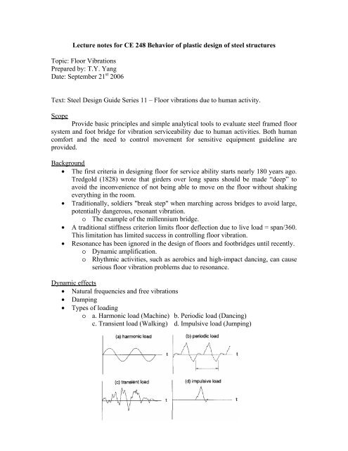
Lecture notes for CE 248 Behavior of plastic design of steel structuresTopic: <strong>Floor</strong> <strong>Vibrations</strong><strong>Prepared</strong> <strong>by</strong>: T.Y. YangDate: September 21 st 2006Text: Steel Design Guide Series 11 – <strong>Floor</strong> vibrations due to human activity.ScopeProvide basic principles and simple analytical tools to evaluate steel framed floorsystem and foot bridge for vibration serviceability due to human activities. Both humancomfort and the need to control movement for sensitive equipment guideline areprovided.Background• The first criteria in designing floor for service ability starts nearly 180 years ago.Tredgold (1828) wrote that girders over long spans should be made “deep” toavoid the inconvenience of not being able to move on the floor without shakingeverything in the room.• Traditionally, soldiers "break step" when marching across bridges to avoid large,potentially dangerous, resonant vibration.o The example of the millennium bridge.• A traditional stiffness criterion limits floor deflection due to live load = span/360.This limitation has limited success in controlling floor vibration.• Resonance has been ignored in the design of floors and footbridges until recently.o Dynamic amplification.o Rhythmic activities, such as aerobics and high-impact dancing, can causeserious floor vibration problems due to resonance.Dynamic effects• Natural frequencies and free vibrations• Damping• Types of loadingo a. Harmonic load (Machine) b. Periodic load (Dancing)c. Transient load (Walking) d. Impulsive load (Jumping)
• Dynamic resonance10987ζ = 0.05ζ = 0.1ζ = 0.2ζ = 0.5ζ = 0.75ζ = 16R d5432100 0.5 1 1.5 2 2.5 3ω / ω no Factors affecting the dynamic amplification: damping, ω andAcceptance criteria for human comfort:• Depends on the people and functionality of the spaceo The reaction of a senior and young adult living in the same apartmentmight have different response to the same floor vibration.o Recommended peak vibration acceleration for human comfort. Figure 2.1.ωnSource: Allen and Murray, 1993; ISO 2631-2:1989.Figure 2.1: Recommended peak floor acceleration for human comfort forvibration due to human activities.
o Acceptance criteria for peak floor acceleration with frequency ranges from4 Hz to 8 Hz.• Office (0.005 g).• Gym (0.05 g) ~ 10 times office acceptance.• Shopping mall (0.015 g) ~ 3 times office acceptance.o Acceptance criteria for peak floor acceleration increases outside thefrequency range from 4 Hz to 8 Hz. See Figure 2.1.• Dynamic force created <strong>by</strong> human activitieso F() t = Pαcos( 2πf t)• P = person’s weight, take as 157 lb for design.• α = dynamic coefficient.• f = step frequency.o Resonance response functiona F Pαcos( 2πf t)R• = =g W W β• R = reduction factor.• Take into account the full steady state resonance motion isnot achieved for walking and the walking person and the
person annoyed <strong>by</strong> the vibration created <strong>by</strong> walking are notsimultaneously at the same location.• R = 0.7 for footbridge• R = 0.5 for floors• β = modal damping ratio (Table 4.1)• W = effective weight of the flooro For design, peak acceleration•a P0 0exp( −0.35 f n )=g βW• P0= 92 lb for footbridge (157x0.83x0.7 = 92)• P0= 65 lb for floors (157x0.83x0.5 = 65)o Rhythmic excitationa 1.3 αw0p/ wt• =g222⎡⎛ fn⎞ ⎤ ⎡2βfn⎤⎢⎜ − 1⎥+f⎟ ⎢f⎥⎢⎣⎝ ⎠ ⎥⎦⎣ ⎦• fn= natural frequency of the floor structure• f = forcing frequency• wp= effective weight of the participant (Table 5.2 and Table 5.3)• wt= total weight of the area (Table 5.3)• For fn= fa 1.3 α w /0 pwt=g 2β• For fn> 1.2 fa 1.3 αw/0pwt=2g ( fn/ f ) −1• For design purpose, the natural frequency of the structural systemmust be much greater than the forcing frequency to avoidresonance hence,k αwpfn≥ f 1+a / g w( )0t
• de= effective depth = depth of the concrete slab + half ofthe distance from the beam flange to the slab.• n = dynamic modulus ratio = Es/1.35 Ec.• Dj= It/ S transformed moment of inertia for the T-beamper unit width (12 in).• It= transformed moment of inertia for the T-beam.• S = joist or beam spacing• Lj= joist or beam span• Girder panel mode• ( ) 1/4 2B C D / D L•gg=g j g g≤ floor width.3C = 1.6 for girder support joist connecting to girder flange.Cg= 1.8 for girder support joist connecting to girder web.Dg = Ig / Ljtransformed moment of inertia for girder perunit width.D = 2 I / L for edge girder.g g j• Lg= girder span• For beam joist or girder are continuous over their span and theadjacent span is greater than 0.7 of the current span, W can beincreased <strong>by</strong> 50% to account for the continuity effect. Nocontinuity effect is added if the girder is connected to the column.• Combine modejg• W ∆ ∆= Wj+ Wg∆ +∆ ∆ +∆j g j g• ∆jand∆gare the maximum deflection of the joist andgirder respectively.• If Lg < Lj, the section is effectively stiffened, where thedeflection in the girder can be reduced usingLgLg∆g' = ∆g, where 0.5 < < 1.BBjj
o Minimum floor stiffness• For fn> 9 Hz, check minimum floor stiffness > 5.7 kips/in (1KN/mm)• Procedure:1. Calculate the maximum deflection at the mid-span of the anequivalent T-beam section with a unit (1 kips) concentratedload at mid-span3Lj∆oj=48 EIs j2. Effective deflection of the joist due to the unit concentratedload (1 kips) at mid-span∆oj∆ = ,jp4d Lj⎛ Lj⎞ewhere Neff= 0.49 + 34.2 + ( 9e−9)−0.00059⎜⎟ ≥1S It⎝ S ⎠4dLjLejfor 0.018 ≤ ≤0.208, 4.5e6 ≤ ≤257e6, 2 ≤ ≤ 30S ItS3. Deflection of the girder due to a unit (1 kips) concentratedload at mid-span3Lg∆gp=96 EIs gThe reduction of the deflection calculation for the girderfrom 48 to 96 is because some partial restrained isaccounted for the girder (not fully pin connection).4. Total floor deflection∆ =∆ +∆ /2N effp jp gp5. Check floor stiffness = 1/ ∆p> 5.7 kips/in2
Design for rhythmic excitation• Rhythmic activities to cause floor vibration were first recognized in 1970National Building Code of Canada (NBC). The code indicates that resonance dueto human activity can be a problem if the floor frequency is less than 5 Hz.• In 1975 NBC increase the value to 10Hz for sensitive activities, such as dancing.• A design criterion was introduced in 1985 and improved in 1990.• Minimum natural frequencyk αwpfn≥ fn,required= f 1+a0/ g wt• a / 0g acceleration limit Table 5.1• k = 1.3 for dancing, k = 1.7 for sport event, k = 2 for aerobics.• f , α wpand wtTable 5.2• Natural frequencygfn= 0.18∆ , where ∆=∆j+∆g+∆c.
Design for sensitive equipment• The design criteria are expressed in terms of the greatest vibration velocity towhich various equipments may be exposed. See Table 6.1• Figure 6.2 shows the velocity limit for microscope equipment.Figure 6.2: Suggest criteria for microscopes.
o Table 6,2 shows the footfall impulse parameterso Maximum static displacement due to footfall impulseXstatic = Fm ∆Pwhere F is located from Table 6.2m∆ is the deflection of the floor.Po Maximum displacementXmax= Fm∆pAmwhere Amis the dynamic amplification factor shown in Figure 6.5o Maximum dynamic deflection due to footfall impulseFigure 6.5: Maximum dynamic deflection due to footfall impulse.For design criterionA= 2 for f t ≤ 0.5 or•mn 0Am1= for f2 nt0> 0.52( ft)n 0o Maximum velocityVmax= π f X2nmax
o For fn/ f0>> 0.5• Vmax = Uv∆ P/ fn, where U∆PVmax• ≤f Unvv= π F f or located from Table 6.2• Since fnis inversely proportional to the square root of3/2is constant, V is proportional to ∆P.2/3∆ ⎛P2 V ⎞2• = ⎜ ⎟∆P1 ⎝V1⎠m20∆PandWays to remedial floor vibration problem• Relocationo Since everyone has different tolerance in floor vibration. Shuffling thepeople around may reduce a huge cost of retrofitting the entire structure.o Change the location where active activities are expected can achievesimilar effect.• For example. Move the Aerobic class from the roof to thebasement.o Place sensitive equipments away from common wall way. Reduce thepossibility of creating vibration from walking.o Place signs for slow walking to reduce the vibration induced <strong>by</strong> running.o Place sensitive equipments away from the center of the floor since it hasthe largest vibration. One possibility is to place the sensitive equipmentsclose to walls or columns.o Do not place sensitive equipments on a flexible stand. It will amplify thevibration.• Reduce mass. Hence increase floor stiffness.• Stiffening the floor system.o Reduce the floor span.o Since the sensitive equipment usually uses a small amount of floor area.Only stiffen the area close to the sensitive equipment can save some cost.• Adding damping to the floor system. Add non-structural components to interactwith the floor system. Example partition and dry wall.• Passive control. Tuned mass damper.• Active control.Uv