CLINCHER® RP6512-02 Technical Manual - Revision ... - McCoy
CLINCHER® RP6512-02 Technical Manual - Revision ... - McCoy
CLINCHER® RP6512-02 Technical Manual - Revision ... - McCoy
You also want an ePaper? Increase the reach of your titles
YUMPU automatically turns print PDFs into web optimized ePapers that Google loves.
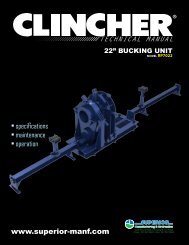
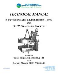
TECHNICAL MANUAL12 3/4” BUCKING UNITm o d e l <strong>RP6512</strong>-<strong>02</strong>• specifications• maintenance• operationwww.superior-manf.com4225 Hwy 90 East • Broussard, LA 70518Phone: 337.837.8847 • Fax: 337.837.8839
© Copyright 2010 Superior Manufacturing & Hydraulics (A Division Of <strong>McCoy</strong> Corporation), all rights reserved.This document is the property of Superior Manufacturing & Hydraulics and is supplied as reference informationfor users of our products. This document and the contents within are considered confidential information, not tobe disclosed, copied, transmitted, transcribed in any form, or stored on any type of data storage media without theexpress written consent of Superior Manufacturing & Hydraulics.While continually striving to maintain accuracy, Superior Manufacturing & Hydraulics hereby states that the informationcontained in this technical documentation is subject to change without notice. If you feel this documentdoes not meet your needs, please contact our sales office for the most current available documentation for yourproduct.II
Table of ContentsSection I ------------------------------------------------------General Description -------------------------------------------------- 2Safety Guidelines ---------------------------------------------------- 2Section II -----------------------------------------------------Maintenance -------------------------------------------------------- 2Section III -----------------------------------------------------Equipment Specifications ---------------------------------------------- 2Lubrication Specifications ---------------------------------------------- 3Dimensional Drawings- ------------------------------------------------ 4Section IV -----------------------------------------------------Setup & Installation Instructions ----------------------------------------- 5Section V -----------------------------------------------------Bucking Unit Hydraulic Schematic ---------------------------------------- 12Control Console Hydraulic Schematic ------------------------------------- 13Electrical Schematic -------------------------------------------------- 14Power Unit Hydraulic Schematic ----------------------------------------- 16Section VI -----------------------------------------------------Assembly Drawings -------------------------------------------------- 191
LUBRICATION SPECIFICATIONSUse an EP synthetic grease that meets or exceeds the following specifications:(Used in tong case)Use an EP synthetic grease that meets or exceeds the following specifications:(Used as bearing grease)Type High Temp MP Type N/ANLGI Consistency Grade 1 NLGI Consistency Grade 2Color Medium Green Color BlueLithium Complex Soap, wt% Non Soap Lithium Complex Soap, wt% 14Serv. Temperature 0 Deg. F – 450 Deg. F Serv. Temperature N/ABase Oil Viscosity:@ 100º F@ 200º F1300 SUS89 SUSBase Oil Viscosity: @ 40ºC, cStASTM D 445 @ 100ºC, cSt15014.5Viscosity Index 77 Viscosity Index N/APenetration, dmmWorkedASTM D 217Dropping Point, ºFASTM D 566325-340 Penetration, dmmWorked, 60XASTM D 217500 ± Dropping Point, ºFASTM D 2265280450+Rust Protection, 5% SSW N/A Rust Protection, 5% SSWASTM D 5969PassWater Washout%wt loss @ 175ºFN/AWater Washout%wt loss @ 175ºFASTM D 12646.8Timken, OK Load, lbs 50 Timken, OK Load, lbsASTM D 250945Bomb Oxidation100 hrs @ 210ºF, psi dropN/ABomb Oxidation100 hrs @ 210ºF, psi dropASTM D 9425 maxApplicationsHigh & Low Speed Bearings,Wheel Bearings, Pumps, Gears,LubricationApplicationsIndustrial application where a hightemperature/multipurpose extremepressure grease is needed, TrailersUse a premium quality hydraulic fluid that meets or exceeds the followingspecifications:Humble Hydraulic H 68ISO Viscosity Grade 68Base Oil Viscosity:ASTM D 445cSt @ 40ºCcSt @ 100ºC65.08.5Viscosity Index – ASTM D 2270 95Pour Point – ASTM D 97 -9Flash Point – ASTM D 92 C(ºF) 222 (432)Demulsibility – ASTM D 1401 41/39/0 (20)Vickers 104C (IP281)Vickers M-2950-SVickers I-286-SPassQuality LevelQuality LevelTOST – ASTM D 943 2000+3
99 1/2”319 1/2”125 3/4”319 1/2"85 3/4"125 3/4"268"4
SECTION IV - <strong>Manual</strong>/PLC Controlled Bucking UnitINSTALLATION & SETUP INSTRUCTIONSIMPORTANT NOTICE: Insure steps 1 through 7have been completed before notifying SuperiorManufacturing & Hydraulics that a factory technicianis needed to perform installation inspection and finalstartup services. If these steps have not beencompleted, additional charges will be applied whileour technician stands-by for the installation to becompleted by the buyer.1. UNPACK – Inspect for shipping damage and/or missingitems. Immediately document and report any suspectedshipping damage. Remove all banding straps andprotective coverings. Do not remove shipping bolts andbrackets before the Bucking Unit has been moved to itsfinal location and no further handling is required. Referto illustration on page 1-1 to identify location of shippingbrackets and bolts.a. WARNING – CLINCHER® Bucking Units canweigh in excess of than 18,000 lbs. and must behandled with appropriate equipment andprocedure to avoid exposing personnel to hazardsor potentially damaging the equipment.2. READ HAZARD WARNINGS and TECHNICALMANUAL – The first section of the technical manualcontains specific information about Operating Procedureswhich if not strictly followed could result in seriousinjury, loss of life, damage to equipment or damage totubulars. Other important information is containedthroughout the technical manual. Thoroughly familiarizeyourself and others working with you with thisinformation before commencing installation or operation.a. A JSA should be undertaken before commencinginstallation work or using installed equipment.Untrained personnel must not handle, install oroperate this equipment.3. INSTALL - CLINCHER® BUCKING UNITS must beinstalled on a foundation suitable for the weight of theunit, its accessories, pipe handling equipment plus theweight of the heaviest tubulars being processed. Levelingjacks are not provided (but are available as options) andmay be required to insure the unit is supported on each ofthe four corners. When possible, we recommend the unitbe anchored to the foundation using 3/4" anchor bolts.Install the bucking unit, hydraulic power unit and torqueturn control system as required on location. NOTE: Ifpipe roller rack systems are being installed they must beaccurately leveled and aligned with the bucking unit todeliver pipe into the bucking unit on the centerline of therotating tong.b. SUPERIOR strongly recommends the use of ourLASER ALIGNMENT TOOLS to verify properalignment before permanently fixing anchor bolts.c. CAUTION: Failure to align rack centerline withbucking unit may cause tubulars to hang on dieswhen passing through the bucking unit.Misalignment can result in unacceptable torque-turnresults.d. Remove shipping bolts/brackets/etc., as shown inillustration on page 1-1.4. INSTALL Control Console and Hydraulic Power Units atlocations as required. Refer to order documents forlengths of hoses supplied with equipment.5. FILL POWER UNIT RESERVIOR WITHHYDRAULIC FLUID - Unless specifically noted, allhydraulic power units are shipped without hydraulic oil.Refer to order documents to determine the volume ofhydraulic oil required to fill the hydraulic reservoir. TheSUPERIOR Hydraulic Power Units and theCLINCHER® BUCKING UNIT are designed to workwith conventional industrial hydraulic oils. SuperiorManufacturing & Hydraulics utilizes TEXACO RandoHD 68 hydraulic oil. Substitution of brands withcomparable properties is acceptable. Use of low viscosityfluids or high viscosity fluids, synthetic, fire resistant orwater-based fluids should not be considered withoutconsulting with SUPERIOR Manufacturing andHydraulics.a. CAUTION: Insure hydraulic fluid reservoir istotally clean and dry before filling with oil. Allhydraulic fluids, including new hydraulic oil, must befiltered to 5 microns before adding to the reservoir.Fill the hydraulic reservoir with the appropriatefiltered hydraulic fluid to within 4 inches from top ofreservoir.b. CAUTION: Insure the suction isolation valve isopen before starting power unit. Failure to openthis valve will cause catastrophic pump failure.c. Note: The electrically driven hydraulic power unit isequipped with a low fluid level switch which willautomatically shut down HPU electrical motor iffluid level drops below safe operating level. Refillunit before attempting to restart HPU. Some unitsmay be equipped with optional second fluid levelwarning lamp which will flash when fluid level islow but not low enough to cause HPU shutdown.6. CONNECT HOSES - Remove all hose dust caps asrequired and clean all hydraulic quick disconnectcouplings with safety solvent and blow dry using lowpressurecompressed air.SUPERIOR Manufacturing & Hydraulics, Inc.23" CLINCHER® BUCKING UNIT<strong>Revision</strong>: 05/07 Page 4 - 15
SECTION IV - <strong>Manual</strong>/PLC Controlled Bucking UnitINSTALLATION & SETUP INSTRUCTIONSa. Connect airlines to DE-ENERGIZED source of cleanand dry air with maximum supply pressure of 120psi.b. Connect hydraulic hoses and insure all quickdisconnects are fully seated. Connect case drain linedirectly to reservoir, do not attach to a return circuit.c. CAUTION: Failure to connect case drain circuitdirectly to hydraulic reservoir will result in motorshaft seal failure and cause hydraulic leakage thatwill not be covered by your warranty.d. Failure to connect load sense line will inhibit thehydraulic power unit’s ability to automatically shiftinto a standby mode when work is not beingperformed. This may cause undesirable heat buildup, higher energy costs, and could result in shortenedlife of hydraulic fluid and/or components.7. ELECTRICAL POWER FOR HYDRAULIC POWERUNIT – LOCKOUT ELECTRICAL POWER ATDISTRIBUTION POINT. Refer to order documents todetermine the electrical voltage and power requirements.DO NOT ENERGIZE CIRCUITS AT THIS TIME.a. Connect appropriate electrical power to motor starter.Connect remote control cord from control console tohydraulic power unit’s motor starter enclosure.b. Insure all components are electrically interconnectedwith heavy gauge ground wires and to a suitableground rod.c. CAUTION: Use locally licensed electricalcontractors to insure proper hookup complyingwith local electrical codes.8. If unit is to be started up by Superior’s factorytechnicians, STOP installation procedures now andnotify Superior Manufacturing & Hydraulics that theunit is now ready for Superior’s technicians toperform startup services. If owner is performinginstallation and startup, follow procedures in step 9.9. INITIAL START UP –a. CAUTION: Insure all control valve levers are inneutral position.1) Remove cover from HPU pump motor adapterhousing.2) Energize electrical power to HPU starter. Do notenergize air supply at this time.3) Set control console selector switch to manual control(for PLC controlled units only).4) Bump Start and Stop motor controls to verify motordirection of rotation is correct as indicated bydirectional arrow on HPU coupling housing.CAUTION: Running pump in the wrongdirection will cause catastrophic pump failurewhich will not be covered by manufacturer’swarranty. Change direction of motor rotation ifrequired by swapping electrical phases in motorstarter enclosure.5) De-Energize electrical power to HPU starter.Reinstall cover on HPU coupling housing.6) Energize electrical power to HPU starter. Start HPUusing switch on console and allow HPU to run for 10minutes to purge air from primary circuits whilemonitoring for leakage.7) Shift mode shift valve lever to “LOW” position.8) Slowly shift motor valve lever from neutral to“MAKEUP” position and allow the unit to rotate for1 minute.9) Shift motor valve lever to “BREAKOUT” positionand allow the unit to rotate for 1 minute.10) Shift mode shift valve lever to “HIGH” positionwhile rotating in “BREAKOUT” for one minute.11) Reverse motor valve lever to “MAKEUP” and allowunit to rotate for 1 minute.12) Release motor valve lever.13) Return mode shift valve lever to mid or neutralposition.14) Verify hydraulic power unit automatically shifts fromoperating mode to standby mode by observingsystem pressure gage dropping to approximately 500psi a few seconds after the demand for power hasbeen removed.15) Actuate tong clamp valve lever to extend clampingcylinders. Release lever and allow it to return to theneutral position. CAUTION: Do not allowpressure to build beyond 1,000 psi unless the diesand pipe are installed. Pressurizing the tongclamping cylinders without dies and pipe inposition can cause failure of the cylinder glandbolts.16) Actuate tong clamp valve lever to retract clampingcylinders. Release lever and allow it to return to theneutral position.17) Repeat steps 15) and 16) six (6) times.Actuate backup clamp valve lever to extend clampingcylinder. Release lever and allow it to return to theneutral position. CAUTION: Do not allow pressure tobuild beyond 1,000 psi unless the dies and pipe areinstalled. Pressurizing the backup clamping cylinderwithout dies and pipe in position can cause failure ofthe cylinder gland bolts.6SUPERIOR Manufacturing & Hydraulics, Inc.23" CLINCHER® BUCKING UNIT<strong>Revision</strong>: 05/07 Page 4 - 2
SECTION IV - <strong>Manual</strong>/PLC Controlled Bucking UnitINSTALLATION & SETUP INSTRUCTIONS18) Actuate backup clamp valve lever to retract clampingcylinder. Release lever and allow it to return to theneutral position.19) Repeat steps 18) six (6) times and 19) five (5) timesleaving backup in closed position.20) For bucking units equipped with optional hydraulicjacks, pipe rollers, backup carriage positioners, etc.,duplicate steps 18), 19) and 20) for each controlvalve and circuit to purge air and confirm properoperation.21) STOP HPU using switch on console.22) Release any trapped hydraulic pressure by fullyactuating all control valve levers in both directionsseveral times.23) Top off hydraulic fluid level in reservoir to makeupfor volume of fluid used to fill lines and cylinders.NOTE: Some HPU’s may be equipped with optionalfluid level sensors which will shut down the HPU if alow fluid level condition develops.24) INSTALL LOCKOUT on electrical disconnect.25) Install compression load cell (hydraulic or electronicas applicable) through “MAKEUP” window intoposition within the backup. CAUTION: Load cellswith diameters other than 8.750 inches will altertorque handle length and will require compensationto indicate correct torque.26) Attach hydraulic torque gage to control console or rigup electronic torque turn system’s turns encoder,electronic load cell and hydraulic dump valvesolenoid cables (supplied by others) using third partyinstructions as applicable. Set torque turn system fortest sub connection’s makeup torque.27) Install dummy load cell (aluminum or steel blank)through “BREAKOUT” window into position withinthe backup.28) Obtain test sub with threaded connection and startcoupling by hand.29) Install correctly sized dies in tong and backup.REFER TO OPERATING INSTRUCTIONS, DIEINSTALLATION page 5-2 for details regarding dieinstallation and operation.30) REMOVE LOCKOUT from electrical disconnect.31) Restart HPU.32) Actuate backup clamp valve lever to retract clampingcylinder and open the backup. Release lever andallow it to return to the neutral position.33) STOP HPU using switch on console.34) Install test sub in bucking unit with midline ofcoupling approximately adjacent to end of dies in tongto avoid clamping on female thread to be made up.35) Insure test sub is level, positioned vertically oncenter in tong and aligned with centerline of thebucking unit.36) RESTART HPU.37) Actuate tong clamp valve lever to extend clampingcylinders and clamp on the test sub’s coupling.System pressure should rise to approximately 2500psi or pressure established by operator for specifictubular application. CAUTION: Use minimumclamping pressure possible to avoid possiblecrushing damage to tubular goods. Release thelever and allow it to return to the neutral position.38) Actuate backup clamp valve lever to extendclamping cylinder. System pressure should rise toapproximately 2500 psi or pressure established byoperator for specific tubular application. CAUTION:Use minimum clamping pressure possible to avoidpossible crushing damage to tubular goods.Release lever and allow it to return to the neutralposition.39) NOTE: If using smooth aluminum dies or if slippageis experienced, torque capability may be increasedby using GRIT FACE or steel dies. Alternatelyincreasing clamping pressure using intensifiers mayprovide higher torque capability. Refer to Air DrivenHydraulic Intensifier information on pages 10-1 and10-2.a) Energize air circuit. CAUTION: Use minimumclamping pressure possible to avoid possiblecrushing damage to tubular goods.CAUTION: Do not actuate intensifiers unlessthe pipe and the correct sizes of dies areinstalled in the tong and backup. Failure tocomply with this requirement will causeextensive equipment damage and exposepersonnel to dangerous high pressurehydraulic leaks.b) Actuate tong clamp valve lever to extendclamping cylinders and clamp on the test sub’scoupling. System pressure should rise toapproximately 2500 psi or pressure establishedby operator for specific tubular application.CAUTION: Use minimum clamping pressurepossible to avoid possible crushing damage totubular goods. While holding the control valvelever in the clamp position, rotate the tong clampintensify valve allowing air pressure to driveSUPERIOR Manufacturing & Hydraulics, Inc.23" CLINCHER® BUCKING UNIT<strong>Revision</strong>: 05/07 Page 4 - 37
SECTION IV - <strong>Manual</strong>/PLC Controlled Bucking UnitINSTALLATION & SETUP INSTRUCTIONSREMOTELY OPERATED BUCKING UNITS REQUIRE OPTIONAL ELECTRICALLY CONTROLLEDSOLENOID OPERATED HYDRAULIC CONTROL VALVES. ELECTRICAL CONTROL PANELS,PROGRAMMABLE CONTROLLERS, POWER SUPPLIES AND SENSORS ARE OPTIONAL ANDNOT INCLUDED. END USERS WHO ARE PROVIDING THEIR OWN CONTROL SYSTEMS MUSTINSURE THEIR ELECTRICAL CONTROL SYSTEM AND POWER SUPPLIES ARE CAPABLE OFDELIVERING THE CORRECT ELECTRICAL VOLTAGE AND ADEQUATE CURRENT TO POWERTHE SOLENOIDS AS TABULATED BELOW.FUNCTION VOLTAGE Required POWER RequiredProportional motor control module -10VDC to +10VDC 0.80 ampsTong motor control solenoid (1) (from control module)6VDC to 12VDC forward12VDC neutral0.44 amps12VDC to 18VDC reverseTong motor high/low control solenoids (2) 24VDC 0.33 ampsTong motor series/parallel control solenoids (2) 24VDC 0.33 ampsTong cylinder clamp/release control solenoids (2) 24VDC 0.33 ampsBackup cylinder clamp/release control solenoids (2) 24VDC 0.33 ampsTong cylinder intensifier control valve solenoid (3) 24VDC 0.60 ampsBackup cylinder intensifier solenoid (3) 24VDC 0.60 ampsTong motor circuit dump valve solenoid (4) 24VAC/VDC 31w (78VA hold, 264VA inrush)1. Sauer Danfoss PVG120 proportional control valve2. Sauer Danfoss PVG32 on-off control valve – requires two separate signals to control both functions3. Ross 2771B4011 normally closed solenoid valve4. Veljin VVV01 or Denison VV01solenoid operated vent valve (driven by torque-turn computer or PLC supplied by others)b) Energize “low” motor speed, “parallel low”(if equipped) and tong motor valvesolenoids to “makeup” position. Rotatetong in makeup direction until centeringcylinder is in bottom position.8) Feed pipe with coupling into bucking unit untilcoupling is correctly positioned in tong adjacentto dies (sense correct position of coupling usingcustomer supplied proximity switch).9) Energize tong clamp circuit to insure cylindersare extended and gripping pipe.a) Energize tong clamp intensifier if required.b) De-energize tong clamp circuit to allowdirectional control valve to return to neutralposition (clamping pressure will trapped bypilot operated check valves). CAUTION:if clamp circuit is not de-energized toallow hydraulic pressure to bleed offbefore rotating the tong, you willexperience heat buildup in the swivelhousing, premature seal failure, and/oraccelerated wearing of hub sealingsurfaces which will not be covered byyour warranty.10) Energize backup clamp circuit to insure cylinderextends and backup is gripping pipe.a) Energize backup clamp intensifier ifrequired.b) De-energize backup clamp circuit to allowdirectional control valve to return to neutralposition (clamping pressure will be trappedby pilot operated check valves).11) Energize tong motor speed circuit in high orlow, and “series” or “parallel” (if equipped) asrequired.12) Energize tong motor makeup circuit to tightenconnection.a) Monitor makeup of connection, using timeor number of turns, and shift from “HIGH”to “LOW” and “series” to “parallel” modeif required.b) Monitor makeup of connection using torqueturn computer until required torque isreached and computer sends power toenergize dump valve solenoid coilindicating makeup has been completed.SUPERIOR Manufacturing & Hydraulics, Inc.23" CLINCHER® BUCKING UNIT<strong>Revision</strong>: 05/07 Page 4 - 59
SECTION IV - <strong>Manual</strong>/PLC Controlled Bucking UnitINSTALLATION & SETUP INSTRUCTIONSc) NOTE: Torque Turn systems provide analternate means of identifying incorrectmake-ups which must be used to initiate aconnection breakout cycle to permitinspection of connection.13) De-energize tong and backup clamp intensifiercircuits.14) Energize backup retract (open) circuit to insurecylinder retracts and backup opens to clear pipe.Monitor system pressure verses time to verifybackup is fully open (or use customer suppliedproximity switch to sense position).15) De-energize backup retract circuit.16) Energize tong retract (open) circuit to insurecylinders retract and tong opens to clearcoupling. Monitor system pressure verses timeto verify tong is fully open.17) De-energize tong retract circuit.18) Feed pipe to rack to clear Bucking Unit.19) Energize “low” motor speed, “parallel low” (ifequipped) and tong motor valve solenoids to“makeup” position. Rotate tong in makeupdirection until centering cylinder is in BDCposition.20) Optional – De-energize HPU.21) Repeat steps 1 thru 20 as required.SUPERIOR Manufacturing & Hydraulics, Inc.23" CLINCHER® BUCKING UNIT<strong>Revision</strong>: 07/07 Page 4 - 610
Page intentionally left blank11
CLINCHER® RP Bucking Unit with Single Speed Motor & Two Speed GearboxBucking UnitHydraulic Schematic12
Control ConsoleHydraulic Schematic13
<strong>RP6512</strong>-<strong>02</strong>Electrical Schematic14
Page intentionally left blank15
PU5060Electric Power Unit71711121813109161581461543216
Item # Qty.Part NumberPart Name1 1 PU2500-H21 HEAT EXCHANGER COOLER2 13 14 15 16 17 18 19 19-1 19-2 19-3 110 111 112 113 114 115 116 117 118 119 1SLP-1PU5060-S32PU4060-S30PU4060-S33PU2500-H15PU2500-H227003771PU2500-H6PU2500-H18PU4060-S6PU2500-H17PU5060-S1PU4060-S3PU4060-S111446144114291431N/ABAC-5M25RCFF2 STRAINERSIGHT GLASSELECTRIC STARTERFILLER BREATHER CAPLOW OIL SHUTDOWNRETURN FILTERELECTRIC MOTOR HEAT EXCHANGER75CC HYDRAULIC PUMPMOTOR PUMP ADAPTERPUMP SHAFT COUPLINGMOTOR SHAFT COUPLINGMOTOR/PUMP COUPLING SPIDER1800 RPM, 50HP, 380V, 60Hz ELECTRIC MOTORSCHROEDER HIGH PRESSURE FILTERL-SHAPED 150 GAL. HYD. FLUID RESERVOIR1 1/4” MALE QUICK DISCONNECT1” MALE WING TYPE QUICK DISCONNECT3/8” MALE QUICK DISCONNECT1/2” MALE QUICK DISCONNECT1” CK VALVEPRESSURE GAUGE2” SUCTION STRAINER15 1416 131813119.39.29.19 1047 GPM MAX.SET @ 2500 PSILOAD SENSEPRESSURE COMP.81750 HP, 1750 RPM380 VAC, 3 PH, 60 HZ619217
18Page intentionally left blank
<strong>RP6512</strong>-<strong>02</strong>Continuously Rotating Bucking UnitAssembly DrawingsBCHKAFGFEJIDABCDEFGHIJKTail Stock Assembly -------------------------------------------------- 20Tong Assembly ----------------------------------------------------- 22Outer Manifold Assembly -------------------------------------------- 26Pinion Gear Assembly ----------------------------------------------- 28Clutch Gear Assembly ---------------------------------------------- 30Drive Gear Assembly ----------------------------------------------- 32Head Stock Assembly ----------------------------------------------- 34Clamp Cylinder Assembly ---------------------------------------------- 36Pusher Skid Assembly ------------------------------------------------ 38Bolt-On Platform Assembly --------------------------------------------- 39Powered Pinch Roller Assembly- ----------------------------------------- 40Drive Pinch Roller Assembly - - - - - - - - - - - - - - - - - - - - - - - - - - - - - - - - - - - - - - - - - - - 42Idler Pinch Roller Assembly ------------------------------------------- 44<strong>Manual</strong>ly Adjusted Support Jack Stand Weldment ---------------------------- 46Hydraulic Support Rest ------------------------------------------------ 48Integrated Hydraulic Leveling / Elevation Control ----------------------------- 508’ Skid Assembly- ---------------------------------------------------- 52Control Console (P/N CB11<strong>02</strong>4-12)Notice: All drawings contained in this manual are the property of Superior Manufacturing & Hydraulics and are considered confidential. This information may not be used,disclosed, copied, or reproduced in any form, without the express written consent of Superior Manufacturing & Hydraulics.For third party component documentation used within this unit, please contact Superior Manufacturing & Hydraulics.19
25300-6500-12Tail Stock Assembly7159131432110122224 11 20 528 818 192117623729 30 31CAASECTION A-AB321827DETAIL BSCALE 1 : 62618DETAIL CSCALE 1 : 620
300-6500-12Tail Stock AssemblyItem # Qty. Part NumberPart Name1 8 1001 1/8 NPT ZERT2 16 1<strong>02</strong>7 WASHER, LOCK 3/8"3 16 1048 3/8"-16 X 1 1/4" HHCS4 4 1101 NUT, HEX, 1/2-135 4 1187 1 1/2-6 HEX NUT6 12 1210 1"-8 NUT GR. 87 20 1218 1" LW8 4 1223 1 1/2" LOCKWASHER9 8 1224-B 1"-8 NYLOC NUT10 2 3<strong>02</strong>-6500 LOAD CELL BRACKET11 2 303-6500 LOADCELL BRACKET WELDMENT12 2 303B-6500 LOAD CELL DEAD PIN13 4 320-6500 TAILSTOCK SPACER BOLTS14 1 330-6500 DELTA POWER 6 PORT FLOW DIVIDER15 1 350-6500-1 CARRIAGE ASSEMBLY16 2 355A-6500-12 TAILSTOCK SIDE PLATE17 4 356-6500 TAILSTOCK SPACER TUBE18 2 358-6500-12 12 3/4" TAILSTOCK BEARING CAP19 2 359-6500 LOADCELL SPACER ROD20 2 360-6500 LOADCELL SPACER BOLT21 1 372-6500-12 12 3/4" TAILSTOCK VISE ASSEMBLY22 2 508-3500-1 CHAIN BLOCK WELDMENT23 12 74053 1"-8 X 3 3/4" HHCS24 2 9<strong>02</strong>B-3000-1 1" X 7 3/4" HITCH PIN25 2 PH-PIN 3 COTTER PIN 1/4 X 1 1/226 1 SD140-CPO 14" RADIAL CONTACT THIN SECTION BEARING27 1 SD140-XPO 14" FOUR CONTACT THIN SECTION BEARING28 4 400-3000-1 CLAMP CYLINDER ASSEMBLY29 8 1976 CAM FOLLOWER30 8 278 1 1/8” LOCK WASHER31 8 1207A 1 1/8”-12 LOW PROFILE NYLOCK NUT21
200A-6500-12Tong Assembly3938374<strong>02</strong>2
23200A-6500-12Tong Assembly1311107421192222222115363435266432542828312<strong>02</strong>731229225812123212225201829301625363435332222
200A-6500-12Tong Assembly2222DETAIL DSCALE 1 : 42222D166161630DETAIL BSCALE 1 : 4SECTION A-ASCALE 1 : 820B18C18DETAIL CSCALE 1 : 424
200A-6500-12Tong AssemblyItem # Qty. Part NumberPart Name1 2 101 1/4" LOCKWASHER2 2 1<strong>02</strong>3-A 5/16-18 HEX NUT3 2 1<strong>02</strong>3-B 5/16 LOCKWASHER4 57 1<strong>02</strong>7 WASHER, LOCK 3/8"5 4 1046 HHCS 3/8-16 X 3/46 8 1048 3/8"-16 X 1 1/4" HHCS7 48 1049 3/8"-16 X 1 1/2" HHCS8 2 105 1/4"-20 X 1" HHCS GR89 8 1132 SCHCS 1/2"-13 X 1 1/2"10 12 1210 1"-8 NUT GR. 811 12 1218 1" LW12 2 122 5/16" X 1" HHCS13 12 1291 1"-8 X 4" HHCS14 18 1309 DOWELL PIN 3/8" x 1-1/4"15 1 201A-6500 BOTTOM HOUSING LID16 1 2010-6500 12 3/4" INNER MANIFOLD ASSEMBLY17 1 2013-6500 12 3/4" MANIFOLD RETAINER RING18 1 2015-6500-1 CLUTCH GEAR ASSEMBLY19 1 2<strong>02</strong>A-6500 TOP HOUSING LID20 1 2<strong>02</strong>0-6500-1 PINION GEAR ASSEMBLY21 1 203-6500 HEADSTOCK MIDBODY22 1 204-6500-12 OUTER MANIFOLD ASSEMBLY23 1 216-6500 MOTOR MOUNT24 1 217-6000 ORING RETAINER25 1 220-6500-1 SHIFTING COLLAR ASSEMBLY26 1 230-6500-12 COVER PLATE RETAINER27 1 234-6500 AIR CYLINDER WITH BRACKET28 1 235-6000-1 DRIVE GEAR ASSEMBLY29 1 239-6500 CYLINDER MOUNT BRACKET30 1 247-6500 DOUBLE STRAND ROLLER CHAIN31 9 249 1/2"-13 X 2" SHCS32 1 283-6500 SHIFTER WINDOW COVER33 8 230A-6500-12 POLYURETHANE SPACER34 40 230B-6500-12 5/8" BELLEVILLE WASHER35 8 230C-6500-12 5/8" FLAT WASHER36 8 91259A794 5/8" X 1" SHOULDER SCREW37 4 1112 1/2”-13 x 1 1/2” HHCS38 4 1103 1/2” LOCKWASHER39 1 3100-6500 12 3/4” ROTATING HEAD GUARD40 1 250-6500-12 HEAD STOCK ASSEMBLY25
204-6500-12Outer Manifold AssemblyAA SECTION A-A13116721493128151014617226
204-6500-12Outer Manifold AssemblyItem # Qty. Part NumberPart Name1 40 1<strong>02</strong>7 WASHER, LOCK 3/8"2 32 1047 3/8"-16 X 1" HHCS3 8 141 3/8"-16 X 1 3/4" HHCS4 1 2011-6500 12 3/4" OUTER MANIFOLD5 1 204B-6500 SPROCKET6 2 204C-6500 FINAL DRIVE BEARING CAP7 2 204E-6500 GARLOCK OIL SEAL (21238-4305)8 4 225-6500 MANIFOLD KEY9 4 227A-6500 MANIFOLD KEY10 1 269-6500 SPROCKET SPACER11 1 SG140-CPO 14" RADIAL CONTACT THIN SECTION BEARING12 1 SG140-XPO 14" FOUR CONTACT THIN SECTION BEARING13 1 SG250-CPO 25" THRUST THIN SECTION BEARING14 1 SG250-XPO 25" FOR CONTACT THIN SECTION BEARING27
2<strong>02</strong>0-6500-1Pinion Gear Assembly1521018111391211182571417861534SECTION A-ASCALE 1 : 428
2<strong>02</strong>0-6500-1Pinion Gear AssemblyItem # Qty. Part Number Part Name1 3 1001 1/8 NPT ZERT2 8 1<strong>02</strong>7 WASHER, LOCK 3/8"3 1 1034 #10-32 X 1/4" SET SCREW4 2 1040-A 3/8-16 x 3/4 SHCS5 8 1047 3/8"-16 X 1" HHCS6 1 1101 NUT, HEX, 1/2-137 4 1276-B #6-32 X 3/8" MACHINE SCREW8 1 2017-6500 BOTTOM PINION BEARING CAP9 1 2<strong>02</strong>0-6500 PINION SPROCKET10 1 2<strong>02</strong>3-6500 PINION BEARING CAP11 2 2<strong>02</strong>4-6500 PINION GEAR SPACER12 1 207-6500 HIGH PINION GEAR13 1 208-6500 LOW PINION GEAR14 1 40034 COVER PLATE15 1 51031 ENCODER COUPLING MOUNT16 1 51075 ENCODER MOUNTING PLATE17 1 55144 ENCODER COUPLING18 2 6307 1-1/2" BEARING29
2015-6500-1Clutch Gear Assembly12 107115149144148SECTION A-A1413623130
2015-6500-1Clutch Gear AssemblyItem # Qty. Part NumberPart Name1 3 1001 1/8 NPT ZERT2 4 1<strong>02</strong>7 WASHER, LOCK 3/8"3 4 1047 3/8"-16 X 1" HHCS4 1 2015-6500 CLUTCH SHAFT5 1 2015A-6500 CLUTCH WASHER6 1 2015B-6500 BOTTOM CLUTCH SHAFT BEARING CAP7 1 2016-6500 TOP CLUTCH BEARING CAP8 1 209-6500 HIGH CLUTCH GEAR9 1 210-6500 LOW CLUTCH GEAR10 1 211-6500 CLUTCH DRIVE GEAR11 1 308-ZZNR 1-1/2" DEEP GROOVE BALL BEARING12 1 3100-156 EXTERNAL RETAINING RING13 1 6307 1-1/2" BEARING14 4 B-2610 TIMKEN NEEDLE BEARING31
235-6000-1Drive Gear Assembly271943583432
235-6000-1Drive Gear AssemblyItem # Qty. Part Number Part Name1 8 1081 7/16" LOCKWASHER2 8 1084 7/16"-14 x 1 3/4" SHCS3 5 1103 1/2" LOCKWASHER4 5 1110 1/2"-13 x 1" HHCS5 1 212-5000-14T MOTOR DRIVE GEAR (SPLINED)6 2 2-222 O-RING7 1 235-6500 1 SPEED 15 cu.inch MOTOR8 1 235A-6500 MOTOR DRIVE GEAR RETAINER9 2 W43-20-20U 1-1/4" FLANGE33
250-6500-12Head Stock Assembly216 5489734
250-6500-12Head Stock AssemblyItem # Qty. Part NumberPart Name1 16 1<strong>02</strong>7 WASHER, LOCK 3/8"2 16 1046 HHCS 3/8-16 X 3/43 12 1103 1/2" LOCKWASHER4 12 1112-A 1/2"-13 x 2" HHCS5 8 222-6500 HEADSTOCK PIN6 16 222B-3500 CYLINDER PIN RETAINER7 1 240-6500-12 12 3/4" HEADSTOCK VISE WELDMENT8 4 400-3000-1 CLAMP CYLINDER ASSEMBLY9 1 291-6500 HEADSTOCK FLOW DIVIDER ASSEMBLY35
400-3000-1Clamp Cylinder Assembly23 22212018 19SECTION A-A12711621<strong>02</strong>1514135836
400-3000-1Clamp Cylinder Assembly**NOTE**TEST PRESSURE: 2000PSIWORKING PRESSURE: 1500 PSIItem # Qty. Part NumberPart Name1 2 1<strong>02</strong>3-N 5/16" X 5/8" DOWEL PIN2 2 1112 1/2"-13 x 1 1/2" HHCS3 1 1570 3/8" MNPT X 3/8" MJIC STRAIGHT4 2 1577-A 90 3/8" MNPT X 3/8" MJIC5 2 260 5/8-11 x 2 SHCS6 1 400-3000 CYLINDER BLOCK HOUSING WELDMENT7 1 401-3000-1 END PLATE WELDMENDT8 1 4<strong>02</strong>-3000 STANDARD JAW HOLDER9 1 400C-3000 SEALS KIT10 1 403-3000-1 PISTON WELDMENT11 1 404-3000 SEAL PLATE WELDMENT12 1 405-3000 SPLIT RING13 1 406-3000 CLAMP CYLINDER DIE14 2 408-3000 3/8" WASHER15 2 91253B SHCS Flat 1/2"-13 x 7/8"SEALS KIT18 612-6.50-1.50 WEAR BAND #219 437 O-RING20 1800-104 PISTON SEAL21 612-5.50-1.50 WEAR BAND22 U25-5.25-56B ROD SEAL23 ST525 WIPER SEAL37
HBS6512Pusher Skid Assembly14 15941.11 2 6-10_f5ox-s 5/8" ORING X 3/8" MJIC1.10 1 515C-3000 L110 SPIDER1.9 1 515B-3000 MODIFIED 1" L- COPLING1.8 1 515A-3000 1 1/2" L-COUPLING1.7 1 511-6500 TRAVEL MOTOR1.6 2 510C-3000 TRAVERSE SPROCKET KEY1.5 1 509-3000 TRAVEL SPROCKET1.4 2 508-3000 1 1/2" BEARING1.3 1 5<strong>02</strong>B-6500 TRAVEL SPROCKET SHAFT1.2 8 1111 1/2"-13 x 1 1/4" HHCS1.1 8 1103 1/2" LOCKWASHERItem # Qty. Part Number Part Name640-6500 FRONT TRAVERSE SPROCKET ASSEMBLY1.11.21.51.61.41.381.91.101.81.6A2.42.662.51.2B132.11.71.1152.2Item # Qty. Part Number Part Name1 20 1103 1/2 LOCKWASHER (1103)2 8 1111 1/2-13 x 1 1/4 HHCS GR.8 (1111)3 1 3200-6500 SPROCKET COVER ASSEMBLY4 1 639-6500 REAR TRAVERSE SPROCKET ASSEMBLY5 1 640-6500 FRONT TRAVERSE SPROCKET ASSEMBLY.6 1 641-6500 TRAVEL CHAIN7 4 623-6500 ROLLER OPENING COVER8 1 HBS6500 PUSHER SKID WELDMENT9 1 3300-6500 FRONT SPROCKET COVER ASSEMBLY10 3 643-6500 3/8" PIPE CLAMP11 1 642-6500 TRAVERSE MOTOR HARD LINE12 12 110 1/2”-13 x 1” HHCS13 1 570-6500 HOSE TRACK WELDMENT14 8 1046 3/8”-16 x 3/4” HHCS15 8 1<strong>02</strong>7 3/8” LOCKWASHER16 12 1110 1/2”-13 x 1” HHCS314 1517 21 1611DETAIL A DETAIL B639-6500 REAR TRAVERSE SPROCKET ASSEMBLY2.3Item # Qty. Part NumberPart Name2.1 4 1103 1/2" LOCKWASHER2.2 4 1111 1/2"-13 x 1 1/4" HHCS2.3 2 508-3000 1 1/2" BEARING2.4 1 509-3000 TRAVEL SPROCKET2.5 1 510B-3000 TRAVEL SPROCKET SHORT SHAFT2.6 1 510C-3000 TRAVERSE SPROCKET KEY3810
700-6500-1Bolt-On Platform Assembly442341Item # Qty. Part NumberPart Name1 4 1169 3/4"-10 X 5" HHCS GR. 82 4 PU-1167 3/4-10 NYLOCK HEX NUT3 4 1171 3/4" LOCKWASHER4 1 700-6500 PLATFORM WELDMENT5 2 710A-6500 PLATFORM MOUNT WELDMENT#16 1 722-6500 XL SERIES SAFETY GATE39
800-6500Powered Pinch Roller Assembly1011121932134681271716 185515881440
800-6500Powered Pinch Roller AssemblyItem # Qty. Part Number Part Name1 16 1171 3/4" LOCKWASHER2 16 1201 3/4"-10 X 1 1/2" HHCS3 1 8<strong>02</strong>-6500 TOP SECTION WELDMENT4 1 803-6500 10" BORE AIR CYLINDER WITH 12" STROKE5 2 803A-6500 1 3/8" PIN SPACER6 1 803C-6500 1 3/8" PIN7 1 803D-6500 1 3/4" PIN8 2 803E-6500 1 3/4" PIN SPACER9 2 808-6500-1 SPROCKET ASSEMBLY10 1 810-6500-1 DRIVE PINCH ROLLER ASSEMBLY11 1 820-6500-1 IDLER PINCH ROLLER ASSEMBLY12 2 823-6500 PINCH ROLLER MOUNT WELDMENT13 2 826-6500 4 FOOT TRAVEL CHAIN14 1 PH-PIN 3 COTTER PIN 1/4 X 1 1/215 1 PH-PIN 2 COTTER PIN 1/4 X 216 6 1976 2 1/4" HEAVY DUTY CAM FOLLOWER17 6 278 1"-8 LW18 6 1207A 1-12 NYLOCK JAM NUT (1213)41
810-6500-1Drive Pinch Roller Assembly1912 5172151761816439148131110SECTION A-A42
810-6500-1Drive Pinch Roller AssemblyItem # Qty. Part NumberPart Name1 4 1103 1/2" LOCKWASHER2 2 1151 5/8 LW3 8 1178 7/8"-14 JAM NUT4 8 1182 7/8 HI-COLLAR LW5 4 171 1/2"-13 x 1 3/4" HHCS6 4 194 5/8-11 NC NUT (194)7 2 196 HHCS 5/8"-11 X 1"8 8 1978 FCF-2 FLANGE CAM FOLLOWER9 3 246 1/2-13 x 1 SHCS10 2 508A-3500 5/8"-11 THREADED ROD11 8 807-6500 WASHER12 1 810-6500 DRIVE PINCH ROLLER WELDMENT13 1 812A-6500 ROLLER BEARING CAP14 1 812B-6500 1" DOUBLE SEALED BALL BEARING15 1 821-6500 1" TWO FLANGE BEARING16 2 825-6500 CHAIN BRACKET17 1 CB7005 L100 FLEXIBLE COUPLING18 1 CB7006-01 V-ROLLER WITH 1 1/2" ROLLER SHAFT19 1 VB1<strong>02</strong>9 HYDRAULIC MOTOR - 45.5 cu. inch/rev.43
820-6500-1Idler Pinch Roller AssemblyA111041498SECTION A-AA135151123267944
820-6500-1Idler Pinch Roller AssemblyItem # Qty. Part NumberPart Name1 4 1151 5/8 LW2 16 1178 7/8"-14 JAM NUT3 16 1182 7/8 HI-COLLAR LW4 4 194 5/8-11 NC NUT (194)5 4 196 HHCS 5/8"-11 X 1"6 16 1978 FCF-2 FLANGE CAM FOLLOWER7 6 246 1/2-13 x 1 SHCS8 2 508A-3500 5/8"-11 THREADED ROD9 16 807-6500 WASHER10 2 812A-6500 ROLLER BEARING CAP11 2 812B-6500 1" DOUBLE SEALED BALL BEARING12 1 820-6500 IDLER PINCH WELDMENT13 2 821-6500 1" TWO FLANGE BEARING14 2 825-6500 CHAIN BRACKET15 2 CB7006-01 V-ROLLER WITH 1 1/2" ROLLER SHAFT45
1120-6500-1<strong>Manual</strong>ly Adjusted Support Jack Stand1013111253721496846
1120-6500-1<strong>Manual</strong>ly Adjusted Support Jack StandItem # Qty. Part Number Part Name1 4 1081 7/16" LOCKWASHER2 4 1085 7/16"-14 X 1 3/4" HHCS3 4 1103 1/2" LOCKWASHER4 1 1120-6500 MANUALLY ADJUSTED SUPPORT JACK STAND WELDMENT5 4 1111 1/2"-13 x 1 1/4" HHCS6 5 1151 5/8 LW7 2 1922 1" PILLOW BLOCK BEARING8 5 194 5/8-11 NC NUT (194)9 5 204 5/8"-11 X 3" HHCS10 2 6408K14 1" L100 COUPLING HUB W/ KEYSLOT11 1 6408K75 L100 SPYDER12 1 CB7006-01 V-ROLLER WITH 1 1/2" ROLLER SHAFT13 1 VB1<strong>02</strong>9 HYDRAULIC MOTOR - 45.5 cu. inch/rev.47
1125-6500-1Hydraulic Support Rest12773864548
1125-6500-1Hydraulic Support RestItem # Qty. Part NumberPart Name1 2 1123-3000 TRANSFER BALL ROLLER2 1 1130-6500 TOP SECTION WELDMENT3 1 1140-6500 BOTTOM SECTION WELDMENT4 5 1151 5/8 LW5 5 194 5/8-11 NC NUT (194)6 5 204 5/8"-11 X 3" HHCS7 1 901D-3000 2" BORE CYLINDER WITH 6" STROKE8 1 9<strong>02</strong>B-3000-1 1" X 7 3/4" HITCH PIN49
630-6500-1Integrated Hydraulic Leveling / Elevation Control1.81.31.11.21.71.51.10A1.41.61.121.111.9DETAIL A1235450
630-6500-1Integrated Hydraulic Leveling / Elevation ControlItem # Qty. Part Number Part Name1.1 2 613-6500 LONG 2" SHAFT1.2 1 614-6500 SHORT 2" OD SHAFT1.3 6 615-6500 2" X 7/8" 15S COUPLING1.4 1 615A-6500 1 3/4" X 7/8" 15S COUPLING1.5 1 631-6500 1 & 2 INPUT BG150S BEVEL GEAR MACHINE SCREW JACK1.6 1 632-6500 1 & 3 INPUT BG150S BEVEL GEAR MACHINE SCREW JACK.1.7 1 633-6500 2 INPUT LEFT HAND BG150S BEVEL GEAR MACHINE SCREW JACK.1.8 1 634-6500 1 & 2 INPUT LEFT BG150S BEVEL GEAR MACHINE SCREW JACK.1.9 1 CB22009-S9 10:1 GEARBOX REDUCER1.10 1 CB22009-S15 DRIVE MOTOR - 8.0 cu.inch/rev.1.11 1 CB22011 MOTOR ADAPTER1.12 1 CB22038 MOTOR ADAPTER SHAFT- 13T 16/32DP x KEYItem # Qty. Part Number Part Name1 1 630-6500 INTEGRATED HYDRAULIC LEVELING/ELEVATION CONTROL2 1 621-6500-1 SCREW JACK AND ROLLER ASSEMBLY3 1 622-6500 FRONT CHAIN MOUNT BRACKET WELDMENT4 1 CB22032 STOP POST WELDMENT5 2 CB22033 ELEVATION STOP51
500-6500-88’ Skid Assembly11181<strong>02</strong>331072918 10792612141319215204241715221652
500-6500-88’ Skid AssemblyItem # Qty. Part NumberPart Name1 4 1<strong>02</strong>3-B 5/16 LOCKWASHER2 2 1<strong>02</strong>7 WASHER, LOCK 3/8"3 2 1047 3/8"-16 X 1" HHCS4 16 1103 1/2" LOCKWASHER5 12 1111 1/2"-13 x 1 1/4" HHCS6 4 1112 1/2"-13 x 1 1/2" HHCS7 16 1151 5/8 LW8 4 122 5/16" X 1" HHCS9 16 194 5/8-11 NC NUT (194)10 16 203 5/8"-11 x 2 3/4" HHCS11 1 500A-6500-8 8 FOOT SKID WELDMENT12 1 5<strong>02</strong>B-6500 TRAVEL SPROCKET SHAFT13 4 508-3000 1 1/2" BEARING14 2 509-3000 TRAVEL SPROCKET15 1 510B-3000 TRAVEL SPROCKET SHORT SHAFT16 3 510C-3000 TRAVERSE SPROCKET KEY17 1 511-6500 TRAVEL MOTOR18 1 515-6500 SPROCKET COVER WELDMENT19 1 515A-3000 1 1/2" L-COUPLING20 1 515B-3000 MODIFIED 1" L- COPLING21 1 515C-3000 L110 SPIDER22 1 527-6500-8 12 FOOT TRAVEL CHAIN23 4 540-3000 BUMPER STOP ASSEMBLY24 2 6-10_f5ox-s 5/8" ORING X 3/8" MJIC25 1 630A-6500 GEAR BOX MOUNT26 2 8 WTX-S 1/2" MJIC BULKHEAD FITTING53


