

1 RIPPLE TANK - with rippler & kit - Serrata Science Equipment
1 RIPPLE TANK - with rippler & kit - Serrata Science Equipment
1 RIPPLE TANK - with rippler & kit - Serrata Science Equipment

Create successful ePaper yourself
Turn your PDF publications into a flip-book with our unique Google optimized e-Paper software.
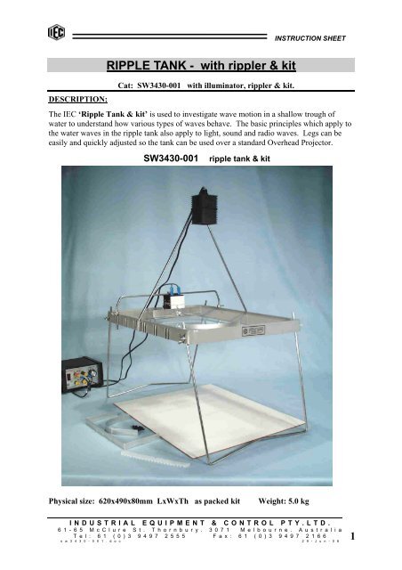
INSTRUCTION SHEETDESCRIPTION:<strong>RIPPLE</strong> <strong>TANK</strong> - <strong>with</strong> <strong>rippler</strong> & <strong>kit</strong>Cat: SW3430-001 <strong>with</strong> illuminator, <strong>rippler</strong> & <strong>kit</strong>.The IEC ‘Ripple Tank & <strong>kit</strong>’ is used to investigate wave motion in a shallow trough ofwater to understand how various types of waves behave. The basic principles which apply tothe water waves in the ripple tank also apply to light, sound and radio waves. Legs can beeasily and quickly adjusted so the tank can be used over a standard Overhead Projector.SW3430-001ripple tank & <strong>kit</strong>Physical size: 620x490x80mm LxWxTh as packed <strong>kit</strong>Weight: 5.0 kgINDUSTRIAL EQUIPMENT & CONTROL PTY.LTD.6 1 - 6 5 M c C l u r e S t . T h o r n b u r y . 3 0 7 1 M e l b o u r n e . A u s t r a l i aT e l : 6 1 ( 0 ) 3 9 4 9 7 2 5 5 5 F a x : 6 1 ( 0 ) 3 9 4 9 7 2 1 6 6s w 3 4 3 0 - 0 0 1 . d o c 2 9 - J u n - 0 61
INSTRUCTION SHEETThe unit consists of:• 1x. Tank, 540x420mm, <strong>with</strong> glass bottom 380x260mm, and folding legs.• 1x Ripple generating unit <strong>with</strong> inbuilt speed control(connects to any standard laboratory supply, up to 12V.AC/DC.)• 1 pr. cables and plugs for Ripple Generator.• 1x. Set of ‘dippers’ of various shapes to fit the Ripple Generator.• 1x. Set of ‘barriers’ to place in the water to disturb ripples.• 1x. Rail for supporting the Ripple Generator (fits to tank).• 1x. Rail for supporting Light Source (fits to tank).• 1x. Illuminating light source, cable and plugs (12V.AC/DC).• 1x. White faced screen to view wave images.Using an Electronic Stroboscope: (Not included in standard <strong>kit</strong>)A Xenon Stroboscope (IEC LB3808-001) may be used as a light source above the rippletank. It may be held or mounted above the ripple tank instead of the standard simple lightsource for certain experiments.When using the Strobe light to illuminate the tank, synchronize the frequency of the Strobeflash <strong>with</strong> the frequency of the waves so that they appear stationary on the white faced screenplaced on the bench beneath the tank. The synchronising frequency is the highest Strobefrequency which appears to 'stop' the waves <strong>with</strong>out creating a double image. Alternatively,using the Stroboscope, observe the ripple generator itself. When it appears to have stoppedoscillating, this is the synchronised frequency.Features of the IEC Ripple Tank:This IEC design can be used as either a normal ripple tank on the bench or a ripple tank foruse <strong>with</strong> an overhead projector (projector not supplied in the <strong>kit</strong>). The adjustable legs arelong enough to support the tank above the Fresnel lens of the standard models of overheadprojector used in most schools. The tank can rest on the screen of the overhead projector,but it is better if it is supported on its own adjustable legs to avoid unwanted vibration fromthe projector’s cooling fan.The tank is corrosion resistant and is provided <strong>with</strong> sturdy fold-away legs for compactstorage. Each leg has individual height adjustment. The tank itself has 'Beached' sides sothat waves are absorbed and not reflected from the sides back into the tank. The tank has astrong glass bottom panel because plastic materials scratch easily and do not retain a flatclear surface over the life of the equipment.The tank is complete <strong>with</strong> various mounting guides for the illumination support and the<strong>rippler</strong> support frames. Except for a simple power supply, ancillary equipment is notrequired to operate the IEC ripple tank.INDUSTRIAL EQUIPMENT & CONTROL PTY.LTD.6 1 - 6 5 M c C l u r e S t . T h o r n b u r y . 3 0 7 1 M e l b o u r n e . A u s t r a l i aT e l : 6 1 ( 0 ) 3 9 4 9 7 2 5 5 5 F a x : 6 1 ( 0 ) 3 9 4 9 7 2 1 6 6s w 3 4 3 0 - 0 0 1 . d o c 2 9 - J u n - 0 62
INSTRUCTION SHEETFig 1 Fig. 2Fig. 1 shows ripple generator clamped to the support rod (looking from the top). Thegenerator can clamp to the rod also at 90 0 around.Fig. 2 shows ripple tank assembly <strong>with</strong> ripple generator mounted on its support rod. Note thetwo cams protruding from the side plates. These cams can be rotated relevant to one anotherto set the phase between them.Fig. 3 Fig. 4Fig.3 shows a ripple tank assembly <strong>with</strong> the Illuminator attached to its support frame by therubber ring. It is positioned approximately over the centre of the tank. The Illuminatorconnects to any 12V.AC/DC power source and the images are viewed on the flat white screenwhich is positioned on the table under the ripple tank.Fig 4 shows the rays of light passing through the waves which behave like lenses. This effectcauses a focussing of the light on each wave and bright and dark bands of light are seen onthe white screen.NOTE: Shallow water always provides a better image resolution than deep water.INDUSTRIAL EQUIPMENT & CONTROL PTY.LTD.6 1 - 6 5 M c C l u r e S t . T h o r n b u r y . 3 0 7 1 M e l b o u r n e . A u s t r a l i aT e l : 6 1 ( 0 ) 3 9 4 9 7 2 5 5 5 F a x : 6 1 ( 0 ) 3 9 4 9 7 2 1 6 6s w 3 4 3 0 - 0 0 1 . d o c 2 9 - J u n - 0 66
INSTRUCTION SHEETFig.5 Fig. 6Figs. 5 & 6 show that shallow water provides a greater proportional variation in water depththan deep water. Therefore shallow water provides better images than deep water. For bestresults, keep the water depth in the ripple tank to a practical minimum.Fig. 7 Fig. 8Fig. 7 shows that for REFRACTION experiments, there must be a very large difference inwater depth. Also lower frequency waves give better results than higher frequencies. Whena thick glass slab (not supplied in standard <strong>kit</strong>) is placed into the tank to create a largedifference in water depth, be sure the water is just covering the glass.Fig. 8 shows the straight aluminium <strong>rippler</strong> <strong>with</strong> the thin edge downwards for thin straightripples and <strong>with</strong> the folded thick edge downwards for large ripples.Fig. 9 Fig. 10Fig. 9 shows the ripple generator and its speed adjustment knob fitted <strong>with</strong> a straight sheet<strong>rippler</strong> <strong>with</strong> one or more point source tips fitted. All point sources dip into the water at thesame time to create a multiple point source.Fig. 10 shows ripple generator and its speed adjustment knob <strong>with</strong> a separate point sourcefitted to opposite side plates to permit the adjustment of phase between them. This providestwo point sources <strong>with</strong> adjustable phase.INDUSTRIAL EQUIPMENT & CONTROL PTY.LTD.6 1 - 6 5 M c C l u r e S t . T h o r n b u r y . 3 0 7 1 M e l b o u r n e . A u s t r a l i aT e l : 6 1 ( 0 ) 3 9 4 9 7 2 5 5 5 F a x : 6 1 ( 0 ) 3 9 4 9 7 2 1 6 6s w 3 4 3 0 - 0 0 1 . d o c 2 9 - J u n - 0 67
INSTRUCTION SHEETREFLECTIONS FROM A STRAIGHT BARRIER:The following sketches show straight line and point source ripples approaching the barriers.The reflected ripple is to be examined by the student.Fig.11Fig.12Straight ripples approaching an angled barrier and circular ripples to a straight barrier.Fig.13Straight ripples to reflect from a straight barrier.REFLECTIONS FROM A CURVED BARRIER:Fig. 14 Fig. 15INDUSTRIAL EQUIPMENT & CONTROL PTY.LTD.6 1 - 6 5 M c C l u r e S t . T h o r n b u r y . 3 0 7 1 M e l b o u r n e . A u s t r a l i aT e l : 6 1 ( 0 ) 3 9 4 9 7 2 5 5 5 F a x : 6 1 ( 0 ) 3 9 4 9 7 2 1 6 6s w 3 4 3 0 - 0 0 1 . d o c 2 9 - J u n - 0 68
DOUBLE OR SINGLE DIFFRACTION AND INTERFERENCE:INSTRUCTION SHEETFig. 16 Fig. 17Double and Single slits are formed by placing the barriers as shown above.The interference pattern formed by the two slits is clearly seen in the image.Fig.18Triple slits are formed by leaving a 5mm gap between the two barriers.If a barrier is required <strong>with</strong>out slits, use the plain legs of each ‘L‘ shaped barrier and positionthem so that the tips touch together. See Fig. 13.Designed and manufactured in AustraliaINDUSTRIAL EQUIPMENT & CONTROL PTY.LTD.6 1 - 6 5 M c C l u r e S t . T h o r n b u r y . 3 0 7 1 M e l b o u r n e . A u s t r a l i aT e l : 6 1 ( 0 ) 3 9 4 9 7 2 5 5 5 F a x : 6 1 ( 0 ) 3 9 4 9 7 2 1 6 6s w 3 4 3 0 - 0 0 1 . d o c 2 9 - J u n - 0 69


