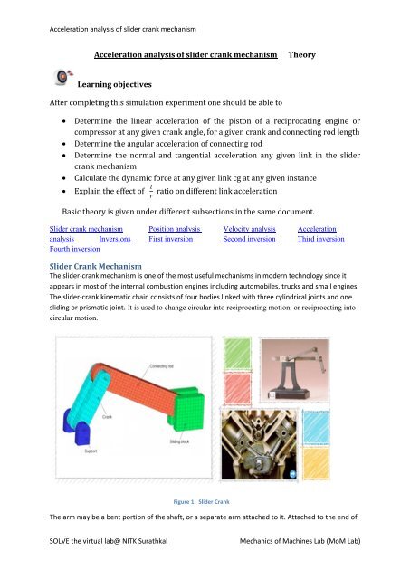
Acceleration analysis of slider crank mechanism Theory Learning ...
Acceleration analysis of slider crank mechanism Theory Learning ...
Acceleration analysis of slider crank mechanism Theory Learning ...

You also want an ePaper? Increase the reach of your titles
YUMPU automatically turns print PDFs into web optimized ePapers that Google loves.
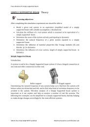
̇<strong>Acceleration</strong> <strong>analysis</strong> <strong>of</strong> <strong>slider</strong> <strong>crank</strong> <strong>mechanism</strong>Velocity AnalysisLet ̇ be the velocity <strong>of</strong> the <strong>slider</strong>, and ω 3 be the angular velocity <strong>of</strong> the coupler link. Then,from the data gleaned from the position <strong>analysis</strong> and the <strong>crank</strong> velocity, ω 2 , we have( )SOLVE the virtual lab@ NITK SurathkalMechanics <strong>of</strong> Machines Lab (MoM Lab)
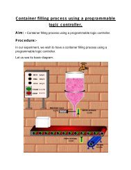
̈<strong>Acceleration</strong> <strong>analysis</strong> <strong>of</strong> <strong>slider</strong> <strong>crank</strong> <strong>mechanism</strong><strong>Acceleration</strong> AnalysisDifferentiating the earlier equations from velocity <strong>analysis</strong>, we end up with the accelerationdata <strong>of</strong> the <strong>slider</strong> <strong>crank</strong>. With the prior knowledge <strong>of</strong> the angular acceleration <strong>of</strong> the <strong>crank</strong>, α 2 ,the parameters such as the linear acceleration <strong>of</strong> the <strong>slider</strong>, ̈, and the angular acceleration <strong>of</strong>the coupler, α 3 .( ) ( )NextSOLVE the virtual lab@ NITK SurathkalMechanics <strong>of</strong> Machines Lab (MoM Lab)
<strong>Acceleration</strong> <strong>analysis</strong> <strong>of</strong> <strong>slider</strong> <strong>crank</strong> <strong>mechanism</strong>InversionsFigure 3: InversionsDifferent <strong>mechanism</strong>s obtained by fixing different links <strong>of</strong> a kinematics chain are known as itsinversions.A <strong>slider</strong>–<strong>crank</strong> chain has the following inversions: -1. First inversion (i.e., Reciprocating engine and compressor)2. Second inversion (i.e., Whitworth quick return <strong>mechanism</strong> and Rotary engine)3. Third inversion (i.e., Oscillating cylinder engine and <strong>crank</strong> & slotted – lever <strong>mechanism</strong>)4. Fourth inversion (Hand pump)PreviousNextSOLVE the virtual lab@ NITK SurathkalMechanics <strong>of</strong> Machines Lab (MoM Lab)
<strong>Acceleration</strong> <strong>analysis</strong> <strong>of</strong> <strong>slider</strong> <strong>crank</strong> <strong>mechanism</strong>First InversionIn this type <strong>of</strong> inversion CE is held fixed and A rotates around C along a circle and B slides back andforth along CE.Figure 4: First InversionFigure 5: Reciprocating EngineThis is the most common type <strong>of</strong> inversion. It is used in reciprocating engine and compressor.PreviousNextSOLVE the virtual lab@ NITK SurathkalMechanics <strong>of</strong> Machines Lab (MoM Lab)
<strong>Acceleration</strong> <strong>analysis</strong> <strong>of</strong> <strong>slider</strong> <strong>crank</strong> <strong>mechanism</strong>Second InversionIn this type <strong>of</strong> inversion ‘C’ and ‘A’ are both held fixed and the link CE rotates in a circlearound C. The <strong>slider</strong> B slides back and forth along the rotating CE.Whitworth Quick-Return MechanismFigure 6: Second InversionIn this inversion <strong>of</strong> the <strong>slider</strong>-<strong>crank</strong> the <strong>slider</strong> guide link is made to rotate. This is called a quick-return<strong>mechanism</strong>. This linkage also converts rotary motion <strong>of</strong> the <strong>crank</strong> into oscillatory angular motion <strong>of</strong>the <strong>slider</strong> guide link. This <strong>mechanism</strong> is used in shaper machine tools for cutting metals. JosephWhitworth was a 19th century British engineer and inventor.Figure 7: Whitworth Quick-Return MechanismPreviousNextSOLVE the virtual lab@ NITK SurathkalMechanics <strong>of</strong> Machines Lab (MoM Lab)
<strong>Acceleration</strong> <strong>analysis</strong> <strong>of</strong> <strong>slider</strong> <strong>crank</strong> <strong>mechanism</strong>Third InversionIn this type <strong>of</strong> inversion A and B are both held fixed but the <strong>slider</strong> is allowed to swivel.Figure 8: Third InversionFigure 9: Oscillating CylinderThe oscillating cylinder engine is a form <strong>of</strong> a <strong>slider</strong>-<strong>crank</strong> <strong>mechanism</strong>. This <strong>mechanism</strong> is used <strong>of</strong>ten in doordamper <strong>mechanism</strong>s. In the 19th century the oscillating cylinder was used on steam locomotives.PreviousNextSOLVE the virtual lab@ NITK SurathkalMechanics <strong>of</strong> Machines Lab (MoM Lab)
<strong>Acceleration</strong> <strong>analysis</strong> <strong>of</strong> <strong>slider</strong> <strong>crank</strong> <strong>mechanism</strong>Fourth InversionIn this type <strong>of</strong> inversion the <strong>slider</strong> B is held fixed and CE slides back and forth through the <strong>slider</strong>.Figure 10: Fourth InversionExample: Hand pumpPreviousSOLVE the virtual lab@ NITK SurathkalMechanics <strong>of</strong> Machines Lab (MoM Lab)