030-856a MAW-603 w-screws - Del Mar Fans and Lighting
030-856a MAW-603 w-screws - Del Mar Fans and Lighting
030-856a MAW-603 w-screws - Del Mar Fans and Lighting

Create successful ePaper yourself
Turn your PDF publications into a flip-book with our unique Google optimized e-Paper software.
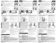
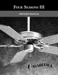
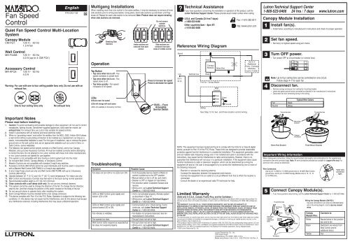
®Fan SpeedControlEnglishQuiet Fan Speed Control Multi-LocationSystemCanopy ModuleCM-FQ1:Wall ControlMA-FQ4M:120 V~ 60 Hz1.0 A fanAccessory ControlMA-AFQ4:120 V~ 60 Hz4.0 A (up to 4 CM-FQ1)120 V~ 60 Hz4.0 AWarning: For use with one to four ceiling paddle fans only. Do not use with anexhaust fan.One to four ceiling fans onlyNo exhaust fansP/N 033-102Multigang InstallationsWhen installing more than one control in the same wallbox, it may be necessary to remove all innerside sections prior to wiring (see below). Using pliers, bend side sections up <strong>and</strong> down until theybreak off. Repeat for each side section to be removed. Note: Product does not require deratingwhen side sections are removed.OperationBreaking SideSectionsTap Button• Tap once when fan is off - <strong>Fans</strong>peed increases to preset level.• Tap once when fan is on - <strong>Fans</strong>peed slows to off.• Tap twice quickly - Fan speedincreases to full speed.LEDsIndicate exact fan speedLEDs will change with each press(LEDs not available on Accessory Controls)Inside sections areremoved from eachcontrolDo not removeoutsidesections.Side sections areremoved from bothsides of middle controlPress to increase fan speedPress to decrease fan speedFASSTM - FrontAccessibleService Switch?Technical AssistanceIf you have questions concerning the installation or operation of this product, call theLutron Technical Support Center. Please provide exact model number when calling.U.S.A. <strong>and</strong> Canada (24 hrs/7 days):+1-800-523-9466Other countries 8am – 8pm ET:+1-610-282-3800Reference Wiring DiagramNeutralLive120 V~60 HzSwitched LiveWhiteCanopyModuleBlackFirst Fan / Canopy ModuleWallboxYellow (Fan)WallControlBrassBrassBlackGreenGroundFax +1-610-282-6311http://www.lutron.comSee Step 12 for two- <strong>and</strong> three-location control wiring.Up to 3Additional<strong>Fans</strong> / CanopyModules(up to 4 total)Lutron Technical Support Center1-800-523-9466 24 hrs / 7 days www.lutron.comCanopy Module Installation1234Install fan(s).• Install fan(s) according to manufacturer's instructions <strong>and</strong> check for proper operation.Set fan speed.• Set fan(s) to highest speed using pull chains.Turn OFF power.• Turn power OFF at circuit breaker (or remove fuse).ONONONOFFOFFOFFNote: Up to four ceiling fans can be controlled on one circuit.Follow steps 4–7 for each fan.Disconnect fan.• Remove canopy enclosure from ceiling fan mounting bracket.• Leave any green ground wires connected as directed in fan manufacturer's instructions.• Disconnect fan from remaining wiring in the ceiling.FanNeutralBlackWhiteTo junction boxTypical Wire ColorsTo junction boxImportant NotesPlease read before installing.1. Caution: To avoid overheating <strong>and</strong> possible damage to other equipment, do not use to controlreceptacles, lighting fixtures, transformer-supplied appliances, solid state fan motors, orexhaust fans. For exhaust fans use Lutron fully variable fan speed controls.2. Install in accordance with all national <strong>and</strong> local electrical codes.3. When no “grounding means” exist within the wallbox then the NEC® 2002, Article 404-9 allowsa wall control without a grounding connection to be installed as a replacement, as long as aplastic, noncombustible wallplate is used. For this type of installation, cap or remove the greenground wire on the wall control <strong>and</strong> use an appropriate wallplate such as Lutron’s Claro® orSatin ColorsTM series wallplates.4. The Maestro® fan speed control system consists of a Wall Control, one to four CanopyModules, <strong>and</strong> up to two Accessory Controls. All must be installed correctly before attemptingto control the fans. Do not attempt to mix Lutron controls with those from other manufacturers,or mix Lutron controls not labeled for use together.5. This system is not compatible with fans having a control system built into the motor.6. Do not paint Wall Control, Canopy Module, or Accessory Control.7. Maestro Controls are not compatible with st<strong>and</strong>ard 3-way/4-way switches.8. Accessory Controls (MA-AFQ4) cannot be used individually <strong>and</strong> must be used in conjunctionwith a Maestro Wall Control (MA-FQ4M) in a 3-way/4-way application.9. In any 3-way/4-way circuit use only one Wall Control (MA-FQ4M) with up to 2 AccessoryControls (MA-AFQ4).10. Operate between 32 °F (0 °C) <strong>and</strong> 104 °F (40 °C) room temperature. For indoor use only.11. Wall Control <strong>and</strong> Accessory Controls may feel warm to the touch during normal operation.12. Recommended wallbox depth is 2.5" (64 mm) minimum.13. Clean controls with a soft damp cloth only. Do not use any chemical cleaners.14. This system cannot be used to change the direction of the fan. To change the fan direction,stop the fan, <strong>and</strong> then change the position of the switch located on the body of the fan.15. Do not use pull chains to operate fan(s) after installing this system.16. Each Canopy Module must be installed within a fan canopy enclosure.17. This device complies with Part 15 of the FCC Rules. Operation is subject to the following twoconditions: (1) this device may not cause harmful interference, <strong>and</strong> (2) this device must acceptany interference received, including interference that may cause undesired operation.TroubleshootingSymptomFan does not turn ON or no LEDs turn ON.LEDs on Wall Control cycle rapidly <strong>and</strong>bottom LED is ON.LEDs on Wall Control cycle rapidly <strong>and</strong>second lowest LED is ON.Fan vibrates or wobbles.Fan speeds too slow.Wall Control LEDs respond as expected butfan does not respond properly.Possible Cause• Front Accessible Service Switch (FASS) oncontrol is pulled out to the OFF position.• Manual switch on fan is off (ex: pull chain).• Breaker is OFF or tripped (or fuse blown).• Fan direction switch is between forward <strong>and</strong>reverse.• Wiring error, call Lutron Technical SupportCenter at +1-800-523-9466.• Unit is not activated properly. Activate systemas described in Step 15.• Wiring error, call Lutron Technical SupportCenter at +1-800-523-9466.• Communication error. Check wiring; if errorcontinues, call Lutron Technical SupportCenter at +1-800-523-9466.• Fan blades not properly balanced. See fanmanufacturer's instructions.• Fan pull chain not set to high.• Fan pull chain not set to high.• Wiring error, call Lutron Technical SupportCenter at +1-800-523-9466.NOTE: This equipment has been tested <strong>and</strong> found to comply with the limits for a Class B digitaldevice, pursuant to Part 15 of the FCC Rules. These limits are designed to provide reasonableprotection against harmful interference in a residential installation. This equipment generates, uses<strong>and</strong> can radiate radio frequency energy <strong>and</strong>, if not installed <strong>and</strong> used in accordance with theinstructions, may cause harmful interference to radio communications. However, there is noguarantee that interference will not occur in a particular installation. If this equipment does causeharmful interference to radio or television reception, which can be determined by turning theequipment off <strong>and</strong> on, the user is encouraged to try to correct the interference by one or more ofthe following measures:- Reorient or relocate the receiving antenna.- Increase the separation between the equipment <strong>and</strong> receiver.- Connect the equipment into an outlet on a circuit different from that to which the receiver isconnected.- Consult the dealer or an experienced radio/TV technician for help.Limited Warranty(Valid only in U.S.A., Canada, Puerto Rico, <strong>and</strong> the Caribbean.)Lutron will, at its option, repair or replace any unit that is defective in materials or manufacture within one year after purchase. Forwarranty service, return unit to place of purchase or mail to Lutron at 7200 Suter Rd., Coopersburg, PA 18036-1299, postage prepaid.THIS WARRANTY IS IN LIEU OF ALL OTHER EXPRESS WARRANTIES, AND THE IMPLIED WARRANTY OFMERCHANTABILITY IS LIMITED TO ONE YEAR FROM PURCHASE. THIS WARRANTY DOES NOT COVER THE COST OFINSTALLATION, REMOVAL OR REINSTALLATION, OR DAMAGE RESULTING FROM MISUSE, ABUSE, OR DAMAGE FROMIMPROPER WIRING OR INSTALLATION. THIS WARRANTY DOES NOT COVER INCIDENTAL OR CONSEQUENTIALDAMAGES. LUTRON’S LIABILITY ON ANY CLAIM FOR DAMAGES ARISING OUT OF OR IN CONNECTION WITH THEMANUFACTURE, SALE, INSTALLATION, DELIVERY, OR USE OF THE UNIT SHALL NEVER EXCEED THE PURCHASE PRICEOF THE UNIT.This warranty gives you specific legal rights, <strong>and</strong> you may have other rights which vary from state to state. Some states do not allowthe exclusion or limitation of incidental or consequential damages, or limitation on how long an implied warranty may last, so theabove limitations may not apply to you.These products may be covered under the following U.S. patents: 4,992,709; D353,798; <strong>and</strong> corresponding foreign patents. U.S. <strong>and</strong>foreign patents pending. Lutron, Claro, <strong>and</strong> Maestro are registered trademarks <strong>and</strong> FASS <strong>and</strong> Satin Colors are trademarks of LutronElectronics Co., Inc. NEC is a registered trademark of the National Fire Protection Association, Quincy, Massachusetts.© 2006 Lutron Electronics Co., Inc.Lutron Electronics Co., Inc.7200 Suter RoadCoopersburg, PA 18036-1299, U.S.A.Made <strong>and</strong> printed in the U.S.A. 3/06 P/N 033-102 Rev. AImportant Wiring InformationWhen making wire connections, follow the recommended strip lengths <strong>and</strong> combinations for the supplied wireconnectors (see wire connector bag). Note: All wire connectors provided are suitable for copper wire only. Foraluminum wire, consult an electrician.Wire Connectors:Use to join 14 AWG or 12 AWG ground wire to 18 AWG Wall Controlground wire, <strong>and</strong> to join 18 AWG Canopy Module wire to 12, 14, 16or 18 AWG wire.5Twist wireconnectortight.Connect Canopy Module(s).• If you have questions about wiring, call the Lutron Technical Support Center at +1-800-523-9466.SwitchedLive toadditionalfansDown Rod BracketFanTo junction boxSwitchedLiveTo fixtureBlackCanopyModuleNeutralYellowMountingbracketCanopyenclosureWhiteFlush Mount BracketWiring the Canopy Module (CM-FQ1):Use wire connectors to join wires as indicated below<strong>and</strong> in the wiring diagram, <strong>and</strong> to cap any unusedwires.CanopyModule Wire:WhiteBlackYellowConnects to:Neutral wires in the junctionbox <strong>and</strong> to fanSwitched Live wire(s) fromWall Control <strong>and</strong> toadditional fan(s)Fan
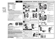
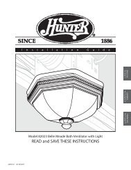
Lutron Technical Support Center 1-800-523-9466 24 hrs / 7 days www.lutron.com66a - Down Rod Bracket• Do not install Canopy Module in ceiling.• Slide Canopy Module into the ceiling fan mounting bracket.6b - Flush Mount Bracket• Do not install Canopy Module in ceiling.• Attach Canopy Module to bracket with a cable tie.• Ensure cable tie does not come in contact with moving motor parts.• Install cable tie through notches on Canopy Module. Pull tight <strong>and</strong> clip excess.NotchInsert Canopy Module.Cable tieTo junction boxTo junction boxControl Installation8 Remove original wallplate <strong>and</strong> switch.• Remove the wallplate <strong>and</strong> switch mounting <strong>screws</strong>.• Carefully remove switches from wall (do not remove wires).9Danger: Verify power toeach switch is OFFbefore proceeding.Identify the circuit type.9a - Single-Location controlGround(Bare Copper orGreen Wire)9b - Two-Location controlNote: Screwplacement maybe different onyour switch.Ground(Bare Copper orGreen Wire)Different coloredscrew (Common)Tagged wireOne switch controlling the fan(s).This switch will be a single-pole. The switch will haveinsulated wires connected to two <strong>screws</strong> of the same colorplus a green ground screw.Two switches controlling the fan(s).Both switches will be 3-way. Each switch will haveinsulated wires connected to three <strong>screws</strong> plus a greenground screw. One of these wires is connected to a screwof a different color (not green) or labeled COMMON. TAGthis wire on both switches to identify when wiring.Important Wiring InformationTrim or strip wallbox wires to the length indicated by the strip gauge on the back of the controlPush-in Terminals: Insert wires fully.NOTE: Push-in terminals are for use with 14 AWG solid copper wire only. DO NOTuse str<strong>and</strong>ed or twisted wire.Screw Terminals: Tighten securely.Screw terminals are for use with 12 or 14 AWG solid copper wire only. DO NOT usestr<strong>and</strong>ed or twisted wire.12BlackscrewORConnect Control(s).• For installations involving more than one control in a wallbox, refer to Multigang Installations beforebeginning.• Only one Wall Control (MA-FQ4M) can be used with up to 2 Accessory Controls (MA-AFQ4).12a - Single-Location controlWall ControlBrass<strong>screws</strong>Green wireReference Wiring DiagramWall ControlGroundWiring the Wall Control (MA-FQ4M):• Connect either of the wires removed from the switchto the black screw terminal on the Wall Control.• Connect the remaining wire removed from the switchto one of the brass screw terminals on the WallControl.• Tighten the remaining brass screw terminal on theWall Control. It is not used in a single-pole circuit.• Use wire connectors to connect the green groundwire on the Wall Control to the bare copper or greenground wire in the wallbox (see Important Note 3),<strong>and</strong> to cap any unused wires.12c - Three-Location controlOne location will be replaced with a Wall Control (MA-FQ4M) <strong>and</strong> the other two with Accessory Controls(MA-AFQ4).Brass<strong>screws</strong>BlackscrewLive120 V~60 Hz13Wall Control orAccessory ControlGreen wireTagged wiresReference Wiring DiagramWall Control orAccessory ControlBrassBrassBlackWallboxGreenGroundGroundWall Control orAccessory ControlBrassBrassBlackGreenWallboxGroundMount Control(s) to wallbox.• Form wires carefully into the wallbox, mount <strong>and</strong> align the Control(s).• Install wallplate(s).Replace the 4-way switchNote: 4-way switch may be replaced with either a WallControl or an Accessory Control• Connect both of the tagged wires removed from the4-way switch to the black screw terminal on theControl (one wire to the screw <strong>and</strong> the other to thepush-in terminal).• Connect one of the remaining wires removed from theswitch to one of the brass screw terminals on theControl.• Connect the remaining wire removed from the switchto the remaining brass screw terminal on the Control.• Use wire connectors to connect the green groundwire on the Control to the bare copper or greenground wire in the wallbox (see Important Note 3),<strong>and</strong> to cap any unused wires.Replace the two 3-way switchesFollow Step 12b - Two-Location control.Wall Control orAccessory ControlBrassBrassBlackWallboxGreenGroundCanopy Module<strong>and</strong> Fan FixtureNeutralCanopy Module<strong>and</strong> Fan FixtureUp to 4 CanopyModules <strong>and</strong> <strong>Fans</strong>7Attach canopy.7a - Down Rod Bracket• Check all wire connections.• Tuck the wires into the junction box <strong>and</strong>/or canopy enclosure.• Attach the canopy enclosure to the fan mounting bracket, taking care not to pinch any wires.To junction box7b - Flush Mount Bracket• Check all wire connections.• Tuck the wires into the junction box <strong>and</strong>/or bracket.• Ensure wires <strong>and</strong>/or wire connectors do not come in contact with moving motor parts.• Attach the canopy enclosure to the fan mounting bracket, taking care not to pinch any wires.9c - Three-Location controlNote: Screwplacement maybe different onyour switch.Same coloredscrew (or markedIN or OUT)Ground(Bare Copper orGreen Wire)10Tagged wiresIdentify switch wires.Important Note:Your wall switch may have two wires attached to the same screw (see illustrations below for examples). Tape thesetwo wires together before disconnecting. When wiring, connect wires to new Controls the same way they wereconnected to the switch.One wire inthe push-interminal <strong>and</strong>one to thescrew.Three switches controlling the fan(s).Two switches will be 3-way <strong>and</strong> one will be a 4-way. TAGthe two 3-way switches as in the Two-Location diagramabove. The 4-way switch will have insulated wiresconnected to four <strong>screws</strong> plus a green ground screw. TAGtwo insulated wires which are connected to same colored<strong>screws</strong>.Onecontinuouswire to thescrew.Live120 V~60 HzWallboxGreenGroundCanopy Module<strong>and</strong> Fan FixtureNeutral12b - Two-Location controlOne location will be replaced with a Wall Control (MA-FQ4M) <strong>and</strong> the other with an Accessory Control (MA-AFQ4).Brass<strong>screws</strong>BlackscrewBrassBrassBlackWall Control <strong>and</strong>Accessory ControlGreen wireTagGroundCanopy Module<strong>and</strong> Fan FixtureUp to 4 CanopyModules <strong>and</strong> <strong>Fans</strong>Wiring the Wall Control <strong>and</strong> Accessory Control:• Connect the tagged wire removed from the switch tothe black screw terminal on the Control.• Connect one of the remaining wires removed from theswitch to one of the brass screw terminals on theControl.• Connect the remaining wire removed from the switchto the remaining brass screw terminal on the Control.• Use wire connectors to connect the green groundwire on the Control to the bare copper or greenground wire in the wallbox (see Important Note 3), <strong>and</strong>to cap any unused wires.1415Start <strong>screws</strong>.Caution: Do notovertightenmounting <strong>screws</strong>.ONONONOFFOFFOFFAlign control <strong>and</strong>tighten <strong>screws</strong>.Turn ON power.• Do not turn on power until Wall Control, Accessory Control(s) <strong>and</strong> Canopy Module(s) have beeninstalled <strong>and</strong> wired.• Turn power ON at circuit breaker (or replace fuse).Warning: Fan(s) will return tofull speed when power isrestored. Clean up any tools orladders near the fan(s) first.Activate system.• Pull out the Front Accessible Service Switch (FASS) at the bottomof the Wall Control, wait 10 seconds, then push it back in.• The LEDs will cycle for up to 30 seconds.• If installing more than one Wall Control/Canopy Module system,activate one at a time with FASS pushed in on all other systems.• Accessory Controls do not require activation.To junction box11Disconnect switch wires.Reference Wiring DiagramWall Control orAccessory ControlWall Control orAccessory ControlScrew Terminals:Turn <strong>screws</strong> to loosen.Push-in Terminals:Insert screwdriver.Pull wire out.Looped Wire:Turn screw to loosen.Live120 V~60 HzBrassBrassBlackGreenGroundWallboxBrassBrassBlackGreenGroundWallboxCanopy Module<strong>and</strong> Fan FixtureNeutralCanopy Module<strong>and</strong> Fan FixtureUp to 4 CanopyModules <strong>and</strong> <strong>Fans</strong>16Recommended - Disconnect pull chains.• Disconnect pull chain extensions to prevent fan speed from being adjusted at the fan(s).