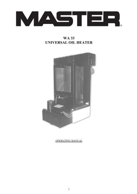
WA 33 UNIVERSAL OIL HEATER
WA 33 UNIVERSAL OIL HEATER
WA 33 UNIVERSAL OIL HEATER

You also want an ePaper? Increase the reach of your titles
YUMPU automatically turns print PDFs into web optimized ePapers that Google loves.
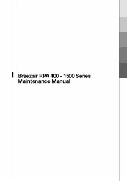
Furnace thermnostatSafety thermnostat (STB)Overflow fuse<strong>WA</strong> <strong>33</strong> controllerFanPumpFig.2. Furnace controller –group of conductors7. Installation of the device- during the installation of the device, meet all the local regulations, including the regulationsreferring to the national and European standards- place the furnace on a flat concrete ground- level the device. In order to check whether the heater is levelled, place the furnace pan in thelower part of the combustion chamber and pour a small amount of diesel oil on it. The oil shouldspread accurately in the middle of the pan.- mount the stabiliser on the pipe coming out from the combustion chamber in order to ensurestable draught during the heater operation.- in order to ensure the optimal draught, install a vertical chimney pipe (not made of aluminium)which is at least 6 meters long, smooth, resistant to high temperature- check the leakproofness of all connections, in case of emergency, use the insulation tape for thepurpose of sealing them- make sure that the combustion pan is placed in the central part of the combustion chamber- place the top ring inside the combustion chamber – the edging in the middle of the ring is placedupwards, - and mount an afterburner cylinder on it (hot air pipe)- check the mains voltage (220-240V/50Hz) and connect the furnace to power supply, neither thefan nor the pump should be started as the furnace has not been switched on yet and no heat hasbeen produced.- maintain a safe distance from inflammable materialsThe air exhaust fans operating in the same room or space as the device may introduce disturbances.Assembly of the chimney pipeIn order to ensure proper burning, it is necessary to provide the properly made chimney installation. Thefollowing recommendations must be met while providing this installation:- minimal pipe diameter: 150mm- check the leakproofness of connections between the chimney elements- minimal chimney height: 6m- the section of the chimney inside the chimney should be insulated (dual wall)- the wind should freely blow around the chimney outlet from all directions (the end of thechimney pipe should be above the roof top)4
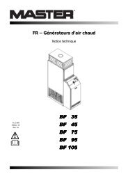
operates until the furnace temperature is below 35°C (damping). After the temperature reaches less than35°C, the furnace returns to the Stop phase.The furnace may be switched off automatically in the following cases:- overheating of the combustion chamber- overflowThe overheating signal is generated by the bimetallic sensor placed nearby the fan. The opening of thecontacts is signalled by the exceeding the threshold temperature value. The control system switches offthe pump (the operation indicator of the pump is not back-lit – yellow diode), the overheating state issignalled by the red diode, which is back-lit on the control panel. The air exhaust fan operates until thefurnace temperature drops below 35°C. After reaching the temperature lower than 35°C, the furnacereturns to the Stop phase.After switching to the Stop phase (and even after switching off and then again switching on thepower supply) the overheating signal is still back-lit. This enables the user to establish the causeof switching off the furnace.In order to clear the overheating signal and return to the normal operation, wait until the furnace is cooledoff (switching off the fan) and press the button placed on the housing of the bimetallic sensor. Then, pressthe Start button, which will cause the lighting of the diode signalling overheating to be switched off. Thefurnace may be restarted.The overflow signal is generated by a mechanical sensor placed under the overflow tank. The opening ofthe contacts signals overfilling the tank. At the same time, the pump is switched on – the pump operationindicator is not back-lit anymore (yellow diode) and instead, the relevant red diode signifying theoverfilling is back-lit. The air exhaust fan operates until the furnace temperature below drops below 35°C.After reaching the temperature lower than 35°C, the furnace returns to the Stop phase. Empty theoverflow tank, and press the Start button, which will cause the (red) diode, which signals overfilling, tobe switched off. The furnace may be restarted..Fig.5. Placement of elements protecting the heater:7
1.Thermostat at the combustion chamber 2. Protection against overheating 3. Overflow protection9. Operation of the heatersNOTEYOU MUST NOT ADD <strong>OIL</strong> TO THE FURNACE AND FIRE IT WHENTHE CHAMBER OR PAN OF THE FURNACE IS STILL HOT!!!AL<strong>WA</strong>YS <strong>WA</strong>IT UNTIL THE BURNER PLATE IS TOTALLY COOLEDOFF. FAILURE TO OBSERVE THE ABOVE-MENTIONEDRECOMMENDATION CREATES A RISK OF UNCONTROLLEDIGNITION OF <strong>OIL</strong> VAPOURS AND BURNING!!!Starting the deviceAfter the heater, it goes through the respective operating conditions depending on the settings introducedby the user and the information received from the sensors attached to the controller system.- in case of emergency, discharge the water from the fuel tank and fill it in with used oil- put the plug of the power cable into the mains socket (230V 50Hz)- open the top part of the heater housing and remove the cover of the combustion chamber, then take outthe cylinder and ring (in the case of necessity, clean the combustion pan and base on which it is placed,but also the whole combustion chamber with a sleeve and the ring)- check whether the furnace pan is cool and clean, then pour about 250 ml of fuel oil or diesel oil- fire the oil, using a piece of paper which is crumpled into a ball for this purpose. the piece of paper mustbe set afire and thrown onto the furnace pan- mount the ring and the cylinder, place the combustion chamber cover, close the top part of the heaterhousing- press the Start button on the control panel (a green diode will be back-lit)- after about 10-15 minutes, depending on the room temperature, the fuel pump and the fan will beswitched on, and at the same time, the yellow diode for pump operation will be back-lit, the furnacewill start to operate on the first gear with a decreased efficiency (22 kW; burning 1.85 kg/h), it mayoperate continuously in this condition, the second gear with an increased efficiency (30 kW: burning2.55 kg/h) may be switched on (marked with ”+” symbol) after 30 minutes from the start of theoperation of the furnace.Each pressing the Stop button and pressing the Start button again and again during itsoperation will cause the furnace to be lit off.Switching off the device- press the Stop button on the control panel (the yellow diode is not back-lit anymore), the pump stopssupplying fuel on the combustion pan, the fan operates until the furnace is cooled off.8
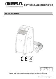
Do not connect the device to the mains, when the fan is in operation, wait until the furnace is cooledoff. The furnace is switched off automatically. Remember that after the device is switched off, thecast-iron pan still maintains the higher temperature for some time (depending on the ambienttemperature) and it is not allowed to switch on the furnace until it is cooled off1. combustion chamber base2. Ring3. combustion chamber4. Cylinder5. Fuel tank6. Pump and controller7. Oil supply conduit8. Furnace chamber coverFig.6. Structure of the heater9
MaintenanceThe heater requires little maintenance activities. The observance of manufacturer’s recommendations willensure fault-free and safe operation of the device.- clean the furnace pan and the elements of the combustion chamber (cylinder, ring and cover) everyday- check the overflow conduit is jammed or not (the conduit in the lower part of the combustion chamber,directly over the overflow tank), clean if necessary- clean the furnace base in the combustion chamber (the element under the furnace pan) at least once aweek- check if the air inlet openings are not covered in the bottom and the top part of the combustion chamber- clean the conduit supplying oil onto the furnace pan, the maximal time of operation of the furnace panwithout cleaning amounts to about 7-14 hours (depending on the applied oil for combustion)- during the heating season, clean the fuel tank and the oil pump filter- if the furnace is inoperable for a longer period of time, clean the combustion chamber and the daily tankaccurately, then protect them from corrosion coating them with a thin layer of oilIT IS RECOMMENDED TO PERFORM PERIODICAL CHECKS AT AN AUTHORISEDSERVICEFurnace baseOverflow conduitFig.7. Combustion chamber10
10. Repair of defectsIn the case of the failure of the device, the list below may help in locating the defect. In general, itsremoval is simple. The most frequent problems are listed below. The digits signify the possible causesThe order of the digits expresses the probability of occurrence of the defect.NOTE:Before starting any activities, pull the plug out of the mains socket.DEFECTCAUSEThe pump does not commence operation and the pump operation control is not lit 6-3-7The flame is put off and the pump is still in operation 2-5-9-10-12The combustion chamber rumbles. 10-11-12There is soot in the combustion chamber and in the chimney 8-9-10-11-12The non-burnt oil remains on the combustion plate.8-9-11-12 or there is too muchdiesel oil at the start-upNo. CAUSE METHOD OF REMOVAL1Lack of power supply.• Check whether the plug is in the socket and checkthe fuses2 Water or deposit in the tank. • Clean the tank and the filter3 The pump motor cannot be switched on • Check the STB and the overflow protection4The motor and the pump are not operable • The fuel is to dense or too cold. Dissolve it withdiesel oil• Check the pump operation control thermostat andreplace it if necessary.• Check the motor and see whether the pump is notdirty inside.• Check the STB and the overflow protection5The fuel conduit is clogged, the oil returnsto the tank by means of the return conduit• Clean the fuel conduit or replace it, if necessaryThe thermostat of the pump operation • Wait until the furnace cools off and restart it6 control has not reached the righttemperature• Replace the thermostat7 Overflow protection is full • Clean it8The safety thermostat (STB) does not • Reset the thermostatoperate correctly or does not operate at all • Replace it9Insufficient combustion air inflow • Clean the openings of the furnace chamber• Check the proper operation of the fanImproper flue draught• Check whether the chimney pipe is mounted inaccordance with the recommendations entitled10„Mounting the chimney flue”• Check the leakproofness of the chimney system• Clean it, if necessary11The flue draught is too strong or too • Mount the flue draught stabiliser and regulate it tovariableminimum 2 mm W.C. (16 Pa).The flue draught is too weak• Check all the connections• Decrease the number of bends12• Extend the chimney• Insulate the chimney pipe outside the building• See all the information regarding the chimney fluein the manual.11
TECHNICAL DATAMinimum thermal efficiency kW 22Maximum thermal efficiency kW 30*Minimum oil consumption kg/h 1,85Maximum oil consumption kg/h 2,55Heated air flow m 3 1000Power supply V/Hz 230/50Power consumption A 0,6Chimney pipe diameter mm 150Width cm 85Height cm 137Length cm 54Weight kg 90„ * ” Thermal efficiency 30kW given for fuel with the following parameters:- calorific value = 40 MJ/kg- density 0.94 cm 3 /kgAt higher parameters, the thermal efficiency may increase even up to 35 kW.Desa Poland Sp. z o.o.62-023 GądkiUl. Magazynowa 5a08EN 1Type: <strong>WA</strong>Distance from the flammable materials: 140 cmDevice class: class 5Heating power: 30 kWFuel type: keroseneElectrical safety: fulfilled12
EC DECLARATION OF CONFORMITYManufacturer: DESA Poland Sp. z o.o.Address:ul. Magazynowa 5A, 62-023 Gądki, PolskaProduct:Marka: MASTERModel: <strong>WA</strong> <strong>33</strong>We herby declare in sole responsibility that the designated product fulfills the safetyrequirements of the European Directives.Directives: 2006/95/WE LOW VOLTAGE DIRECTIVE (LVD)2004/108/WEELECTROMAGNETIC COMPATIBILITY DIRECTIVE (EMC)89/106/WEBUILDING PRODUCTS DIRECTIVEStandards applied:PN-EN 1, PN-EN 1:2001/A1, PN-EN 60<strong>33</strong>5-1, PN-EN 60<strong>33</strong>5-1-102, PN-EN 55014-1:2007,PN-EN 55014-2:1999+A1:2004+IS1:2007, PN-EN 55014-1:2004, PN-EN 61000-3-2004+A2:2005, PN-EN 61000-3-3:1997+A1:2005+A2:2006, PN-EN 55014-1, PN-EN61000-4-2:1999+A2:2003, PN-EN 61000-4-4:2005, PN-EN 61000-4-6:2007. PN-EN 61000-4-5:2006, PN-EN 61000-4-11:2007, PN-EN 61000-3-3:1997+A1:2002(U)CE marking was made in2008rDeclaration issued byDESA Poland Sp z o.o.Place, date Gądki, 2008-08-12Signature of an authorised person13
DESA Italia spaVia Tione 12Pastrengo, Verona (VR)Italy 37010www.desaitalia.comDESA Poland Sp.z o.o.ul. Magazynowa 5a62-023 Gądki, Polandwww.desapoland.plDESA ChinaRm. 601, 218, HengFeng Rd,Shanghai, China, 200070www.desa-china.com14