Scanner 2000 Steam Mass Flow Transmitter ... - Spirax Sarco
Scanner 2000 Steam Mass Flow Transmitter ... - Spirax Sarco
Scanner 2000 Steam Mass Flow Transmitter ... - Spirax Sarco

You also want an ePaper? Increase the reach of your titles
YUMPU automatically turns print PDFs into web optimized ePapers that Google loves.
<strong>Scanner</strong> ® <strong>2000</strong> microEFM Section 3<br />
Power Supply Wiring<br />
Internal Power Supply<br />
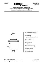
The <strong>Scanner</strong> <strong>2000</strong> microEFM is shipped with a lithium battery pack. To supply power to the instrument,<br />
connect the battery cable to connector J1 on the main circuit assembly (Figure 3.2).<br />
Low-power microprocessor technology enables the <strong>Scanner</strong> <strong>2000</strong> to operate for an estimated 1 year on a<br />
lithium battery pack. The lithium battery pack is ideal for use in extreme temperatures, although extreme cold<br />
temperatures may reduce battery life.<br />
To maximize battery life,<br />
• operate the <strong>Scanner</strong> using the following default configuration settings:<br />
– calculation frequency: 1 minute<br />
– logging frequency (interval): 1 hour<br />
– download frequency: monthly<br />
• disconnect the <strong>Scanner</strong> <strong>2000</strong> from the RS-232 to RS-485 converter when ModWorX Pro software is not<br />
in use. When ModWorX Pro is running, the computer powers the converter; when the software is not running,<br />
the <strong>Scanner</strong> <strong>2000</strong> powers the converter, causing a current drain to the <strong>Scanner</strong> battery.<br />
• avoid the following conditions/activities:<br />
– operation at extremely cold temperatures<br />
– use of digital output (pulse or alarm)<br />
– use of analog input without external power (when expansion board is installed)<br />
1 7<br />
2<br />
8<br />
3<br />
4<br />
SCANNER <strong>2000</strong><br />
Main Circuit Board<br />
PN: 9A-30160010<br />
9<br />
10<br />
5<br />
11<br />
6<br />
12<br />
J2 TB1 TB2<br />
RTD<br />
I+ R+ R- I-<br />
–<br />
TFM 1<br />
+<br />
SWITCH<br />
DIG OUT 1<br />
Figure 3.2—Lithium battery pack connection<br />
13 14<br />
TB3<br />
BATTERY<br />
J1<br />
POWER<br />
PORT 2 PORT 1<br />
+ – + – + –<br />
61