Scanner 2000 Steam Mass Flow Transmitter ... - Spirax Sarco
Scanner 2000 Steam Mass Flow Transmitter ... - Spirax Sarco
Scanner 2000 Steam Mass Flow Transmitter ... - Spirax Sarco

You also want an ePaper? Increase the reach of your titles
YUMPU automatically turns print PDFs into web optimized ePapers that Google loves.
Section 2 <strong>Scanner</strong> ® <strong>2000</strong> microEFM<br />
Installation Procedure—Direct Mount to a Barton 7000 Series Turbine<br />
Meter (ATEX Compliant)<br />
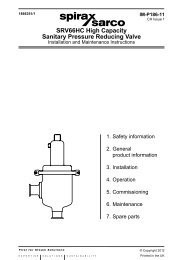
A <strong>Scanner</strong> <strong>2000</strong> without the MVT bottomworks can be mounted directly to a Barton 7000 series turbine meter<br />
for measuring liquid (Figure 2.15). A stainless steel turbine meter pickup extension supports the <strong>Scanner</strong> <strong>2000</strong><br />
and provides the elevation necessary for good visibility of the display.<br />
52<br />
Turbine meter pickup<br />
extension (ATEX-approved)<br />
10 pipe diameters<br />
upstream (minimum)<br />
<strong>Flow</strong><br />
5 pipe diameters<br />
downstream (minimum)<br />
Figure 2.15—Direct-mount installation for use with a Barton 7000 Series meter<br />
To connect the <strong>Scanner</strong> <strong>2000</strong> to a turbine meter using this method, perform the following steps:<br />
1. Position the <strong>Scanner</strong> <strong>2000</strong> and pickup extension assembly above the flowmeter.<br />
2. Plug the <strong>Scanner</strong> <strong>2000</strong> cable connector into the magnetic pickup of the turbine meter and hand-tighten the<br />
knurled nut on the connector.<br />
3. Screw the <strong>Scanner</strong> <strong>2000</strong>/pickup extension assembly onto the flowmeter threads surrounding the magnetic<br />
pickup with the display facing the desired direction, and tighten.<br />
Performing a Manifold Leak Test<br />
A manifold leak test is recommended prior to operating any differential pressure meter into service. Check the<br />
manifold for leaks as follows.<br />
1. Verify that the instrument is approximately level and<br />
is properly connected to the pressure source.<br />
2. Make sure the vent valve in the manifold is closed.<br />
(The bypass/block valves should be open.)<br />
3. Close both bypass/block valves on the manifold to<br />
isolate pressure between the block valve and the<br />
MVT.<br />
4. Open both equalizer valves to distribute pressure throughout.<br />
EQUALIZER<br />
BYPASS/<br />
BLOCK<br />
EQUALIZER<br />
5. Monitor the pressure readout and watch for a steady decrease in pressure. If leakage is indicated, depressurize<br />
the system by opening both bypass/block valves, then check all manifold and piping joints. Tighten<br />
connections as necessary.<br />
VENT<br />
BYPASS/<br />
BLOCK