

Scanner 2000 Steam Mass Flow Transmitter ... - Spirax Sarco
Scanner 2000 Steam Mass Flow Transmitter ... - Spirax Sarco
Scanner 2000 Steam Mass Flow Transmitter ... - Spirax Sarco

You also want an ePaper? Increase the reach of your titles
YUMPU automatically turns print PDFs into web optimized ePapers that Google loves.
<strong>Scanner</strong> ® <strong>2000</strong> microEFM Section 2<br />
Measuring Uncompensated Liquid via a Turbine Meter<br />
Best Practices<br />
The <strong>Scanner</strong> <strong>2000</strong> microEFM calculates uncompensated liquid flow through a turbine meter in accordance<br />
with API MPMS, Chapter 5, Section 3, Measurement of Liquid Hydrocarbons by Turbine Meters. For<br />
optimum performance, ensure that the turbine and <strong>Scanner</strong> <strong>2000</strong> installation complies with the industry<br />
recommendations listed below:<br />
• Install the turbine flowmeter in the meter run such that there are at least 10 nominal pipe diameters upstream<br />
and five nominal pipe diameters downstream of the meter. Both inlet and outlet pipe should be of<br />
the same nominal size as the meter.<br />
• Straightening vanes are recommended for eliminating swirl conditions. If used, they should be installed<br />
five pipe diameters upstream of the meter.<br />
Installation Procedure—Direct Mount to a Turbine Meter (CSA Compliant)<br />
A <strong>Scanner</strong> <strong>2000</strong> without the MVT bottomworks can be mounted directly to a liquid turbine meter for<br />
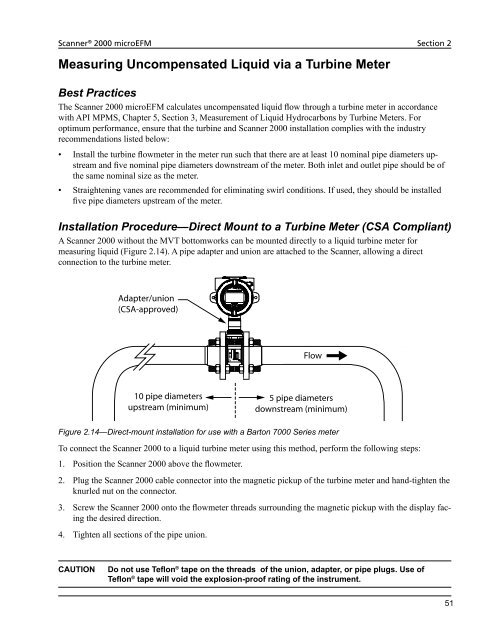
measuring liquid (Figure 2.14). A pipe adapter and union are attached to the <strong>Scanner</strong>, allowing a direct<br />
connection to the turbine meter.<br />
Adapter/union<br />
(CSA-approved)<br />
10 pipe diameters<br />
upstream (minimum)<br />
<strong>Flow</strong><br />
5 pipe diameters<br />
downstream (minimum)<br />
Figure 2.14—Direct-mount installation for use with a Barton 7000 Series meter<br />
To connect the <strong>Scanner</strong> <strong>2000</strong> to a liquid turbine meter using this method, perform the following steps:<br />
1. Position the <strong>Scanner</strong> <strong>2000</strong> above the flowmeter.<br />
2. Plug the <strong>Scanner</strong> <strong>2000</strong> cable connector into the magnetic pickup of the turbine meter and hand-tighten the<br />
knurled nut on the connector.<br />
3. Screw the <strong>Scanner</strong> <strong>2000</strong> onto the flowmeter threads surrounding the magnetic pickup with the display facing<br />
the desired direction.<br />
4. Tighten all sections of the pipe union.<br />
CAUTION Do not use Teflon ® tape on the threads of the union, adapter, or pipe plugs. Use of<br />
Teflon ® tape will void the explosion-proof rating of the instrument.<br />
51


