Scanner 2000 Steam Mass Flow Transmitter ... - Spirax Sarco
Scanner 2000 Steam Mass Flow Transmitter ... - Spirax Sarco
Scanner 2000 Steam Mass Flow Transmitter ... - Spirax Sarco

Create successful ePaper yourself
Turn your PDF publications into a flip-book with our unique Google optimized e-Paper software.
Section 2 <strong>Scanner</strong> ® <strong>2000</strong> microEFM<br />
5. Install the RTD assembly in the thermowell. Remove the plug from a conduit opening in the top of the<br />
<strong>Scanner</strong> <strong>2000</strong> enclosure, route the RTD assembly cable through the conduit opening and connect it to the<br />
main circuit board. A wiring diagram for the RTD assembly is provided in Figure 3.5, page 64.<br />
CAUTION Do not use Teflon ® tape on the threads of the union, adapter, or pipe plugs. Use of<br />
Teflon ® tape will void the explosion-proof rating of the instrument.<br />
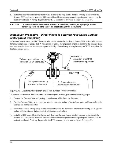
Installation Procedure—Direct Mount to a Barton 7000 Series Turbine<br />
Meter (ATEX Compliant)<br />
A <strong>Scanner</strong> <strong>2000</strong> without the MVT bottomworks can be mounted directly to a Barton 7000 series turbine meter<br />
for measuring liquid (Figure 2.13). A stainless steel turbine meter pickup extension supports the <strong>Scanner</strong> <strong>2000</strong><br />
and provides the elevation necessary for good visibility of the display. An explosion-proof RTD is required for<br />
the temperature input.<br />
50<br />
Turbine meter pickup<br />
extension (ATEX-approved)<br />
10 pipe diameters<br />
upstream (minimum)<br />
<strong>Flow</strong><br />
5 pipe diameters<br />
downstream (minimum)<br />
Figure 2.13—Direct-mount installation for use with a Barton 7000 Series meter<br />
Model 21<br />
explosion-proof RTD<br />
assembly or equivalent<br />
To connect the <strong>Scanner</strong> <strong>2000</strong> to a turbine meter using this method, perform the following steps:<br />
1. Position the <strong>Scanner</strong> <strong>2000</strong> and pickup extension assembly above the flowmeter.<br />
2. Plug the <strong>Scanner</strong> <strong>2000</strong> cable connector into the magnetic pickup of the turbine meter and hand-tighten the<br />
knurled nut on the connector.<br />
3. Screw the <strong>Scanner</strong> <strong>2000</strong>/pickup extension assembly onto the flowmeter threads surrounding the magnetic<br />
pickup with the display facing the desired direction, and tighten.<br />
4. Install the RTD assembly in the thermowell. Remove the plug from a conduit opening in the top of the<br />
<strong>Scanner</strong> <strong>2000</strong> enclosure, route the RTD assembly cable through the conduit opening and connect it to the<br />
main circuit board. A wiring diagram for the RTD assembly is provided in Figure 3.5, page 64.