Scanner 2000 Steam Mass Flow Transmitter ... - Spirax Sarco
Scanner 2000 Steam Mass Flow Transmitter ... - Spirax Sarco Scanner 2000 Steam Mass Flow Transmitter ... - Spirax Sarco
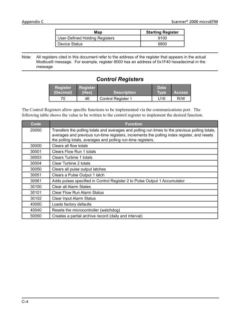
Appendix C Scanner ® 2000 microEFM C-4 Map Starting Register User-Defined Holding Registers 9100 Device Status 9900 Note: All registers cited in this document refer to the address of the register that appears in the actual Modbus® message. For example, register 8000 has an address of 0x1F40 hexadecimal in the message. Register (Decimal) Control Registers Register (Hex) Description Data Type Access 70 46 Control Register 1 U16 R/W The Control Registers allow specific functions to be implemented via the communications port. The following table shows the value to be written to the control register to implement the desired function. Code Function 20000 Transfers the polling totals and averages and polling run times to the previous polling totals, averages and previous run-time registers, increments the polling index register, and resets the polling totals, averages and polling run-time registers. 30000 Clears all flow totals 30001 Clears Flow Run 1 totals 30003 Clears Turbine 1 totals 30004 Clear Turbine 2 totals 30050 Clears all pulse output latches 30051 Clears a Pulse Output 1 latch 30061 Adds pulses specified in Control Register 2 to Pulse Output 1 Accumulator 30100 Clear all Alarm States 30101 Clear Flow Run Alarm Status 30102 Clear Input Alarm Status 40000 Loads factory defaults 40040 Resets the microcontroller (watchdog) 50050 Creates a partial archive record (daily and interval)
Scanner ® 2000 microEFM Appendix C Register (Decimal) System Configuration Register (Hex) Description Data Type Access 1000 3E8 Product Code and Feature Privileges U16 RO 1001 3E9 Register Table Version U16 RO 1002 3EA Firmware Version U16 RO 1003 3EB Manufacture Date U16 RO 1004 3EC Sales Date U16 RO 1005 3ED Serial Number High U16 RO 1006 3EE Serial Number Low U16 RO 1007 3EF Sensor Serial Number[0] PA RO 1008 3F0 Sensor Serial Number[1] PA RO 1009 3F1 Sensor Serial Number[2] PA RO 1010 3F2 Sensor Serial Number[3] PA RO 1011 3F3 Sensor Serial Number[4] PA RO 1012 3F4 Sensor Serial Number[5] PA RO 1013 3F5 Expansion Board Manufacture Date U16 RO 1014 3F6 Expansion Board Sales Date U16 RO 1015 3F7 Expansion Board Serial Number High U16 RO 1016 3F8 Expansion Board Serial Number Low U16 RO 1017 3F9 Expansion Board Configuration U16 RO Product Code The Product Code is a read-only parameter used for identifying a Scanner 2000 device and its enabled advanced features (such as PID controller and Modbus Master) using the ModWorX Pro software. This parameter is defined at the factory. Firmware Version/Register Table Version The Firmware Version and Register Table Version numbers are set by the factory and are read-only. To determine the version number, read the appropriate register and divide the value by 100. The general format for version numbers is A.BC. For example the firmware register number is read as 0xA7 hexadecimal. This represents the value 167 and a firmware version of 1.67. Manufacture Date/Sales Date These parameters are set at the factory and are read-only. These registers are formatted as MMYY. For example, a value of 0908 represents the date September 2008. C-5
- Page 56 and 57: Section 2 Scanner ® 2000 microEFM
- Page 58 and 59: Section 2 Scanner ® 2000 microEFM
- Page 60 and 61: Section 3 Scanner ® 2000 microEFM
- Page 62 and 63: Section 3 Scanner ® 2000 microEFM
- Page 64 and 65: Section 3 Scanner ® 2000 microEFM
- Page 66 and 67: Section 3 Scanner ® 2000 microEFM
- Page 68 and 69: Section 3 Scanner ® 2000 microEFM
- Page 70 and 71: Section 4 Scanner ® 2000 microEFM
- Page 72 and 73: Section 4 Scanner ® 2000 microEFM
- Page 74 and 75: Section 4 Scanner ® 2000 microEFM
- Page 76 and 77: Section 5 Scanner ® 2000 microEFM
- Page 78 and 79: Section 5 Scanner ® 2000 microEFM
- Page 80 and 81: Section 5 Scanner ® 2000 microEFM
- Page 82 and 83: Section 6 Scanner ® 2000 microEFM
- Page 84 and 85: Section 6 Scanner ® 2000 microEFM
- Page 86 and 87: Appendix A Scanner ® 2000 microEFM
- Page 88 and 89: Appendix A Scanner ® 2000 microEFM
- Page 90 and 91: Appendix A Scanner ® 2000 microEFM
- Page 92 and 93: Appendix A Scanner ® 2000 microEFM
- Page 94 and 95: Appendix A Scanner ® 2000 microEFM
- Page 96 and 97: Appendix A Scanner ® 2000 microEFM
- Page 98 and 99: Appendix A Scanner ® 2000 microEFM
- Page 100 and 101: Appendix A Scanner ® 2000 microEFM
- Page 102 and 103: Appendix B Scanner ® 2000 microEFM
- Page 104 and 105: Appendix C Scanner ® 2000 microEFM
- Page 108 and 109: Appendix C Scanner ® 2000 microEFM
- Page 110 and 111: Appendix C Scanner ® 2000 microEFM
- Page 112 and 113: Appendix C Scanner ® 2000 microEFM
- Page 114 and 115: Appendix C Scanner ® 2000 microEFM
- Page 116 and 117: Appendix C Scanner ® 2000 microEFM
- Page 118 and 119: Appendix C Scanner ® 2000 microEFM
- Page 120 and 121: Appendix C Scanner ® 2000 microEFM
- Page 122 and 123: Appendix C Scanner ® 2000 microEFM
- Page 124 and 125: Appendix C Scanner ® 2000 microEFM
- Page 126 and 127: Appendix C Scanner ® 2000 microEFM
- Page 128 and 129: Appendix C Scanner ® 2000 microEFM
- Page 130 and 131: Appendix C Scanner ® 2000 microEFM
- Page 132 and 133: Appendix C Scanner ® 2000 microEFM
- Page 134 and 135: Appendix C Scanner ® 2000 microEFM
- Page 136 and 137: Appendix C Scanner ® 2000 microEFM
- Page 138 and 139: Appendix C Scanner ® 2000 microEFM
- Page 140 and 141: Appendix C Scanner ® 2000 microEFM
- Page 142 and 143: Appendix C Scanner ® 2000 microEFM
- Page 144 and 145: Appendix C Scanner ® 2000 microEFM
- Page 146 and 147: Appendix C Scanner ® 2000 microEFM
- Page 148 and 149: Appendix C Scanner ® 2000 microEFM
- Page 150 and 151: Appendix C Scanner ® 2000 microEFM
- Page 152 and 153: Appendix C Scanner ® 2000 microEFM
Appendix C <strong>Scanner</strong> ® <strong>2000</strong> microEFM<br />
C-4<br />
Map Starting Register<br />
User-Defined Holding Registers 9100<br />
Device Status 9900<br />
Note: All registers cited in this document refer to the address of the register that appears in the actual<br />
Modbus® message. For example, register 8000 has an address of 0x1F40 hexadecimal in the<br />
message.<br />
Register<br />
(Decimal)<br />
Control Registers<br />
Register<br />
(Hex) Description<br />
Data<br />
Type Access<br />
70 46 Control Register 1 U16 R/W<br />
The Control Registers allow specific functions to be implemented via the communications port. The<br />
following table shows the value to be written to the control register to implement the desired function.<br />
Code Function<br />
<strong>2000</strong>0 Transfers the polling totals and averages and polling run times to the previous polling totals,<br />
averages and previous run-time registers, increments the polling index register, and resets<br />
the polling totals, averages and polling run-time registers.<br />
30000 Clears all flow totals<br />
30001 Clears <strong>Flow</strong> Run 1 totals<br />
30003 Clears Turbine 1 totals<br />
30004 Clear Turbine 2 totals<br />
30050 Clears all pulse output latches<br />
30051 Clears a Pulse Output 1 latch<br />
30061 Adds pulses specified in Control Register 2 to Pulse Output 1 Accumulator<br />
30100 Clear all Alarm States<br />
30101 Clear <strong>Flow</strong> Run Alarm Status<br />
30102 Clear Input Alarm Status<br />
40000 Loads factory defaults<br />
40040 Resets the microcontroller (watchdog)<br />
50050 Creates a partial archive record (daily and interval)


