Spiraflo Steam Flowmeters - Spirax Sarco
Spiraflo Steam Flowmeters - Spirax Sarco
Spiraflo Steam Flowmeters - Spirax Sarco
Create successful ePaper yourself
Turn your PDF publications into a flip-book with our unique Google optimized e-Paper software.
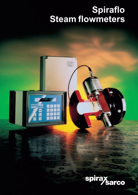
<strong>Spiraflo</strong><br />
<strong>Steam</strong> flowmeters
2<br />
The <strong>Spiraflo</strong> steam meter with density compensation<br />
is designed to give very accurate results,<br />
regardless of variations in steam pressure<br />
How it works<br />
The <strong>Spiraflo</strong> steam meter operates on the wellestablished<br />
spring loaded variable area principle.<br />
A circular plate positioned in the flow is free to move<br />
against the action of a heavy duty precision made<br />
torsion spring. To determine the plate angle, a rotary<br />
transformer of special design is incorporated into the<br />
unit. This converts the plate angle into an electrical<br />
output which is proportional to the flow. The device<br />
operates within the pressurised body of the transducer,<br />
thus eliminating the need for any rotary seals. The<br />
result is a robust design, well suited to the rigours<br />
of steam service. It offers good turndown, high<br />
accuracy and repeatability.<br />
An in-built temperature probe provides information<br />
which enables the flow computer to compensate for<br />
the pressure variations which are commonplace in<br />
steam systems. This density compensation is<br />
essential in achieving accurate measurement<br />
of steam flow.<br />
The addition of a pressure transmitter enables the<br />
<strong>Spiraflo</strong> to be used for superheated steam as well as<br />
saturated steam systems.<br />
Density compensation<br />
It is rare for the pressure in a steam system to<br />
remain absolutely constant. Unless this variation is<br />
taken into account, flow measurement errors will<br />
occur. The automatic<br />
density compensation<br />
offered by the <strong>Spiraflo</strong><br />
system completely<br />
eliminates these errors<br />
1 000<br />
900<br />
800<br />
Flowrate<br />
and allows accurate<br />
700<br />
metering whatever the<br />
600<br />
steam pressure. This is 500<br />
shown in the diagram.<br />
400<br />
300<br />
200<br />
Flowrate, kg / h<br />
PTX<br />
RVDT - Rotary variable differential<br />
transformer<br />
RTD - Resistance temperature<br />
detector<br />
PTX - Pressure transmitter<br />
Signal conditioning unit<br />
(the signal conditioning unit converts<br />
the signal into a form suitable for<br />
use in the flow computer)<br />
Flow computer<br />
Spring loaded plate<br />
RVDT<br />
The <strong>Spiraflo</strong> system components<br />
100<br />
0<br />
0 1 2 3<br />
Cumulative error<br />
4<br />
Hours elapsed<br />
5 6 7<br />
0<br />
8<br />
In this example a simple non-compensated meter is set for 6 bar g. The actual pressure in the system varies<br />
through the day and unless this is allowed for, by the end of the day, very significant errors can arise. This is<br />
typical of many steam systems.<br />
RTD<br />
Actual<br />
system<br />
pressure<br />
10<br />
8<br />
Pressure bar g<br />
6<br />
4<br />
2<br />
2 500<br />
2 000<br />
1 500<br />
1 000<br />
500<br />
0<br />
Cumulative error, kg
Flowrate, kg / h<br />
Good turndown - essential for steam systems<br />
The turndown of a flowmeter is the ratio of the maximum to minimum flowrate over which it will meet its specified<br />
performance. In steam systems, varying load can give rise to wide flow variations and it is essential that a<br />
steam flowmeter can cope with these. It is also very important that it is designed for typical flow velocities that<br />
are encountered in steam systems.<br />
Some flowmeter types require very high velocities (up to 75 m / s) to achieve their claimed performance. In<br />
practice, to reduce noise, erosion and waterhammer, steam flow velocities should be limited to 30 - 35 m / s.<br />
Consider a typical flow pattern for a distributed steam system shown below.<br />
1 000 2 000<br />
Actual flowrate<br />
Cumulative flow error<br />
1 700<br />
750<br />
1 500<br />
500<br />
250<br />
40<br />
25<br />
0<br />
<strong>Spiraflo</strong><br />
1 2 3 4<br />
Hours elapsed<br />
5 6 7 8<br />
Flowrate below minimum of 250 kg / h (i.e. 1 000 kg / h ÷ 4)<br />
10 20 25 30 40 50<br />
Turndown ratios with steam velocities limited to 35 m / s<br />
Cumulative error, kg<br />
Threshold at<br />
4:1 turndown<br />
This graph shows a typical demand curve for a distributed steam system with a high start-up load and variable<br />
demand through the day. An orifice plate meter, with a 4:1 turndown is sized on the peak load of 1 000 kg/h. Any<br />
flowrates below 250 kg/h are ‘lost’ or, at best, recorded with a significant error.<br />
The <strong>Spiraflo</strong> steam meter, with its 25:1 turndown (40:1 intermittent) completely eliminates this type of error.<br />
Comparison of turndown ratios<br />
Good steam practice dictates that flow velocities should be kept below 35 m / s as far as practical to avoid<br />
erosion and possible waterhammer problems. The table below shows the realistic turndown ratios for various<br />
types of steam flowmeter when the steam velocity is limited to 35 m / s.<br />
<strong>Spiraflo</strong><br />
Orifice<br />
Shunt<br />
Vortex<br />
Orifice plate<br />
25:1 continuous<br />
40:1 intermittent<br />
Depends on system pressure.<br />
Typically up to 10:1 with flow velocity of 35 m / s<br />
Typically 7:1<br />
Typically 4:1<br />
1 000<br />
500<br />
3
4<br />
Using a <strong>Spiraflo</strong> steam meter from <strong>Spirax</strong> <strong>Sarco</strong> will enable you<br />
to measure steam use accurately under all load conditions.<br />
It will provide vital information on usage and associated<br />
costs which can improve efficiency in four key areas:-<br />
Plant efficiency<br />
Is idle machinery switched off ?<br />
Is plant loaded to optimum efficiency ?<br />
Identify cleaning and / or maintenance needs.<br />
Identify major steam users.<br />
Highlight peak steam usage times.<br />
Indicate whether working practices are<br />
satisfactory.<br />
Energy efficiency<br />
Monitor the results of energy saving<br />
schemes.<br />
Compare the efficiency of various<br />
pieces of plant.<br />
Process control<br />
Confirm if the correct quantity of steam<br />
at the right pressure and temperature<br />
is being supplied.<br />
<strong>Spiraflo</strong> 6 diameters<br />
Vortex meters - up to 30 diameters<br />
Orifice plates - up to 30 diameters<br />
Weatherproof cable gland<br />
allows outside installation.<br />
Stainless steel cover.<br />
Asbestos free gasket.<br />
Carbon graphite bushes for<br />
zero maintenance.<br />
High accuracy temperature<br />
sensor in stainless steel pocket.<br />
Installation<br />
All flow meters must be correctly installed. For steam systems in particular, care must be taken to ensure correct line drainage and that<br />
adequate lengths of upstream and downstream straight pipe runs are provided. With only six upstream pipe diameters and three<br />
downstream pipe diameters required, <strong>Spiraflo</strong> installations are extremely compact.<br />
10 20 30<br />
Number of upstream diameters of straight pipe<br />
Costing<br />
Cost steam as a raw material.<br />
True cost of individual product lines can be<br />
established.<br />
Relate steam energy costs to total plant<br />
efficiency.<br />
Check individual plant performance.<br />
Charge for steam usage.<br />
6 pipe diameters<br />
(minimum)<br />
3 pipe<br />
diameters<br />
(minimum)
Heavy duty, precision made<br />
nickel cobalt spring for long<br />
term stability.<br />
Stainless steel plate.<br />
Cast steel or SG iron body in<br />
sizes DN40 to DN100.<br />
Flanged construction for quick<br />
and easy installation.<br />
M210G flow computer gives<br />
automatic density compensation<br />
plus analogue, pulse and<br />
RS232C outputs as standard.<br />
Local signal conditioning<br />
allows M210G flow computer<br />
to be installed over 300 m<br />
from metering location.<br />
Available displays<br />
Flowrate<br />
Totalised flow<br />
Time and date<br />
Temperature and pressure<br />
Peak rate and time<br />
Four batching timers<br />
Eight day repeating batch<br />
timer<br />
High / low flowrate alarm<br />
High / low pressure /<br />
temperature alarm<br />
User benefits<br />
● Purpose designed for steam with density<br />
compensation and dryness fraction correction.<br />
● Flow computer can be sited up to 300 m away<br />
from the pipeline unit.<br />
● Easy to install and use, with accurate password<br />
protected 16 digit alpha numeric display.<br />
● Built-in choice of imperial or metric units with<br />
flow expressed in terms of energy or mass.<br />
● Battery back-up to protect setting information.<br />
● RS232C interface port - compatible with energy<br />
management systems.<br />
5
6<br />
M111 series transducer<br />
This is fitted in the steam line and provides analogue<br />
flow and temperature signals to the M322 signal<br />
conditioning unit. These units must be fitted<br />
within two meters of each other.<br />
EL2600 pressure transmitter<br />
Only required for superheat conditions.<br />
Provides 4 - 20 mA pressure signal to the M322<br />
signal conditioning unit.<br />
M322 signal conditioning unit<br />
Converts flow, pressure and temperature signals into<br />
digital form for transmission to M210G flow computer<br />
which can be located up to 300 metres away.<br />
EL2600<br />
pressure<br />
transmitter<br />
Separator<br />
➤<br />
Isolating valve<br />
M322 signal<br />
conditioning unit<br />
The ability of any flowmeter to perform to specification<br />
and give years of trouble-free service is, to a large<br />
degree, governed by the way it is installed. This is<br />
especially true for steam systems where there are<br />
always potential difficulties from surges and<br />
waterhammer arising from poor line drainage.<br />
Whatever kind of flowmeter is used, it is essential to<br />
install it properly:-<br />
System details<br />
Y-type<br />
strainer<br />
Installation<br />
Air vent<br />
➤<br />
D<br />
➤<br />
➤<br />
Trapping set<br />
M210G series flow computer<br />
Executes all the necessary calculations to provide<br />
density compensation. Gives local display of rate,<br />
total, pressure and temperature. Provides timer<br />
functions, programmable outputs and alarms.<br />
➤<br />
6 D<br />
Minimum<br />
M111<br />
series transducer<br />
➤<br />
<strong>Spiraflo</strong> meter<br />
M210G series flow computer<br />
Ensure adequate lengths of upstream and<br />
downstream straight pipe (only six pipe diameters<br />
upstream and three downstream are required for<br />
the <strong>Spiraflo</strong>).<br />
Install a steam separator and strainer<br />
upstream of the flowmeter to give good steam<br />
quality and help avoid waterhammer.<br />
Provide adequate steam trapping.<br />
Avoid installing the flowmeter immediately<br />
downstream of a pressure reducing valve.<br />
Avoid rapid actuation valves.<br />
Avoid reverse flow by fitting a check valve.<br />
➤<br />
3 D ➤<br />
Minimum<br />
➤<br />
Check valve<br />
➤<br />
➤<br />
➤
Flow capacities for saturated steam<br />
<strong>Steam</strong> pressure (bar g)<br />
Size Flowrate kg / h 1 2 3 4 5 6 7 8 9 10 11 12 13 14 15 16 17<br />
a) Maximum 610 740 845 940 1 020 1 100 1 175 1 240 1 300 1 365 1 425 1 480 1 530 1 585 1 635 1 685 1 730<br />
DN40 b) At 35 m / s velocity 180 260 350 420 500 580 660 740 820 900 970 1 050 1 120 1 200 1 275 1 350 1 440<br />
c) Minimum 15 18 21 23 25 27 29 31 33 34 36 37 38 40 41 42 43<br />
a) Maximum 955 1 155 1 320 1 470 1 600 1 720 1 830 1 940 2 035 2 130 2 225 2 310 2 395 2 475 2 555 2 630 2 705<br />
DN50 b) At 35 m / s velocity 280 410 540 660 790 910 1 030 1 150 1 275 1 400 1 520 1 640 1 760 1 870 1 990 2 100 2 250<br />
c) Minimum 25 28 33 37 40 43 46 48 51 53 56 58 60 62 64 66 68<br />
a) Maximum 2 445 2 955 3 380 3 755 4 095 4 400 4 690 4 960 5 215 5 460 5 690 5 915 6 130 6 335 6 540 6 730 6 920<br />
DN80 b) At 35 m / s velocity 720 1 050 1 375 1 695 2 010 2 330 2 640 2 945 3 265 3 580 3 885 4 195 4 490 4 800 5 105 5 415 5 755<br />
c) Minimum 60 74 84 94 102 110 117 124 130 136 142 148 153 158 163 168 172<br />
a) Maximum 3 820 4 615 5 285 5 870 6 395 6 880 7 330 7 750 8 150 8 530 8 895 9 240 9 575 9 900 10 215 10 515 10 815<br />
DN100 b) At 35 m / s velocity 1 125 1 640 2 145 2 645 3 140 3 640 4 125 4 600 5 100 5 590 6 070 6 555 7 020 7 495 7 980 8 460 9 000<br />
c) Minimum 95 115 132 147 160 172 183 194 204 213 222 231 239 247 255 263 270<br />
Notes on the above table<br />
The steam meter will continue to give a reading up to the maximum value in the<br />
above table. However, the steam flow velocities at these maximum flowrates could be<br />
extremely high (up to 120 m /s at the low pressures and up to 42 m /s at the high<br />
pressures) and could lead to serious erosion damage both to the transducer and to<br />
the associated pipework and fittings. It is not recommended that a flowmeter is selected<br />
to operate at flowrates continuously resulting from a velocity above 35 m /s.<br />
Flow capacities for superheated steam<br />
In general terms, the flow capacity for the transducer is calculated using the<br />
following equation:-<br />
Q =<br />
AV<br />
Sv<br />
x 3600<br />
Where :- Q = Capacity in kg / h<br />
A = Pipe cross sectional area in m²<br />
V = Flow velocity in m / s<br />
Sv = Specific volume in m³ /kg<br />
Approximate dimensions and weights (mm, kg).<br />
M111 series transducer<br />
PN BS10 ANSI ANSI JIS<br />
25 H 150 300 20<br />
Size A A A A A C D E F Weight<br />
DN40 176 175 175 181 176 180 100 76 28 9.5<br />
DN50 180 178 178 184 176 180 100 76 28 10.5<br />
DN80 240 236 240 249 236 220 152 76 76 25.0<br />
DN100 260 263 260 276 260 220 152 76 76 34.5<br />
E<br />
EL2600 pressure transmitter<br />
EL2600<br />
A B C D E Weight<br />
73 50 36 13 30 0.1<br />
U - syphon and isolating valve<br />
F G H J K L M Weight<br />
297 160 70 170 145 69 25 0.5<br />
C<br />
D<br />
C D A<br />
A<br />
E<br />
B<br />
K<br />
M<br />
F<br />
G<br />
L<br />
H<br />
J<br />
F<br />
Turndown of the transducer is defined as the maximum flow divided by the<br />
minimum flow: using the maximum figures from the above table, the turndown is<br />
40:1 throughout the size and pressure range. However, based on the<br />
recommended maximum velocity of 35 m/s, the turndown available will vary<br />
from 12:1 at 1 bar g up to 33:1 at 17 bar g. The average continuous turndown of<br />
the flowmeter is therefore 25:1.<br />
The saturated steam flow capacities in the above table are calculated using this<br />
equation. Superheated steam flow capacities can be calculated in the same way.<br />
Example: What is the capacity of a DN80 transducer on superheated steam at<br />
5 bar g and 200°C.<br />
Assume maximum velocity = 35 m / s Sv = 0.4252 m³ / kg.<br />
Q = 3.14 x 0.08 x 0.08 x 35 x 3600 = 1 489 kg / h<br />
4 x 0.4252<br />
M322 signal conditioning unit<br />
A B C D E F G H I Weight<br />
250 175 75 198 232 27 40 85 130 0.8<br />
G<br />
H I<br />
B<br />
A<br />
F<br />
M210G series flow computer<br />
Wall mounting<br />
A B C D E F G H J K Weight<br />
185 138 170 50 130 170 100 20 92 52 1.9<br />
Panel mounting<br />
A B C D E F Weight<br />
192 144 156 140 186 40 1.7<br />
E<br />
B<br />
B<br />
A<br />
A<br />
F<br />
C<br />
C<br />
H<br />
C<br />
D<br />
E<br />
J<br />
K<br />
K J<br />
D<br />
F<br />
E<br />
D<br />
E<br />
7
M111 series transducer<br />
Sizes available: DN40, 50, 80, 100<br />
Flanges M111 BS 4504 PN25<br />
BS 10, Table H<br />
JIS 10, JIS 20<br />
ANSI B16.5 Class 150 & 300<br />
M115 BS 4504 PN25<br />
BS 10 Table H<br />
JIS 10, JIS 20<br />
ANSI B16.5 Class 150 & 300<br />
Body materials M111-SG Iron DIN 1693 GGG40<br />
M115-Steel DIN 17245 GSC2<br />
Internal materials - mostly stainless steel<br />
Torsion spring material - nickel cobalt alloy<br />
Gaskets - exfoliated graphite (EFG)<br />
Principle of operation - spring loaded variable area<br />
Flow medium - saturated or superheated steam<br />
Flow capacities - see tables<br />
Maximum operating temperature - 230°C<br />
Maximum operating pressure - 17 bar g<br />
Minimum operating pressure - 1 bar g<br />
Dimensions and weights - see table on page 7<br />
Turndown - 40:1 intermittent, 25:1 continuous<br />
Accuracy a) ± 1 % FSD at 50 % of flow, b) ± 2 % of actual flow<br />
Installation - straight pipe lengths: 6 D upstream, 3 D downstream<br />
(D = normal pipe diameter)<br />
Mounting - horizontal, vertical (flow down) acceptable<br />
M322 signal conditioning unit<br />
The M322 signal conditioning unit accepts temperature and flow signals<br />
from the M111 transducer as well as a 4 - 20 mA analogue pressure<br />
signal from an EL2600 pressure transmitter. These signals are<br />
converted into digital form for onward transmission to the M210G flow<br />
computer which can be located up to 300 m away.<br />
Materials of construction of enclosure - polycarbonate<br />
Dimensions and weights - see table on page 7<br />
Enclosure rating: IP65 (when fitted with suitable cable glands)<br />
Type of mounting: Wall mounting using brackets supplied<br />
Maximum operating temperature: 65°C<br />
Supply voltage - 24 Vdc (from M210G computer)<br />
Channel Input Output<br />
Port 1 Analogue input from Frequency signal<br />
M111 transducer (150 - 1500 Hz) which<br />
proportional to plate is proportional to flow<br />
deflection angle through the M111<br />
(using RVDT) i.e.: flow transducer.<br />
Port 2 Analogue input from Frequency signal<br />
(temperature) Pt100 temperature (150 - 1500 Hz) which<br />
sensor incorporated is proportional to<br />
into M111 transducer measured temperature<br />
Port 3 4 - 20 mA from EL2600 Frequency signal<br />
(pressure) series pressure (150 - 1500 Hz) which<br />
transmitter Max. loop is proportional to<br />
impedance = 150 ohms<br />
Open circuit<br />
voltage = 15 volts<br />
measured pressure<br />
EL2600 pressure transmitter<br />
NB. This is only required for superheated steam applications<br />
Options available for use 0 - 1.6 bar g<br />
with <strong>Spiraflo</strong> 0 - 2.5 bar g<br />
0 - 4.0 bar g<br />
0 - 6.0 bar g<br />
0 - 10.0 bar g<br />
0 - 16.0 bar g<br />
0 - 25.0 bar g<br />
'U' Syphon assembly<br />
Process connection<br />
Mount the EL2600 via a ¼" BSPP connection into the 'U' syphon<br />
assembly and mount the 'U' syphon assembly via a ¼" BSPP connection<br />
directly into the pipework.<br />
Full installation details are supplied with the EL2600.<br />
Maximum pressure<br />
EL2600 - The rated pressures can be exceeded to the following limits<br />
without degrading performance: 3 bar for 1.6 bar g range.<br />
3 times FS (Full Scale) for ranges 2.5 to 25 bar g.<br />
'U' syphon - the 'U' syphon is pressure rated for use with the pressure<br />
transmitters listed above.<br />
Burst pressure<br />
EL2600 only - 50 bar for ranges 0 to 25 bar g.<br />
Maximum temperature<br />
With 'U' syphon - up to 450°C maximum.<br />
Enclosure rating<br />
IP65 to BS 5490 (IEC 529).<br />
Accuracy<br />
0.5 % FSD (including hysteresis, repeatability and thermal error).<br />
Output<br />
2 wire 4 - 20 mA current loop.<br />
Supply - 24 Vdc standard (11 to 33 Vdc operable).<br />
Maximum loop resistance 650 W at 24 Vdc.<br />
Connection via 4 pole plastic connector.<br />
Materials of construction<br />
EL2600 - wetted parts stainless steel plus stainless steel body with<br />
moulded plastic head and connector assembly. 'U' syphon assembly<br />
zinc plated carbon steel tube (BS 1706) with plated carbon steel valve<br />
colour passivated to DEF 130.<br />
Dimensions and weights<br />
See table on page 7.<br />
M210G series flow computer<br />
Function - carry out all signal processing and provide local display of<br />
flow, total, pressure, time and date.<br />
Units of display - metric or imperial. Flow parameters can be<br />
displayed in mass or energy units.<br />
Full density compensation inbuilt.<br />
Customer programmable for steam quality correction.<br />
4 batching timers with peak flow capture.<br />
1 x 8 day repeating timer.<br />
High / low flowrate alarm.<br />
High / low pressure alarm.<br />
High / low temperature alarm.<br />
Battery back-up for clock and flow data.<br />
Access security code protected.<br />
Programmable 4 - 20 mA analogue output for flowrate (kg / h).<br />
Programmable pulse output for total flow kg.<br />
RS232C interface.<br />
Can be located up to 300 m from point of flow measurement.<br />
Supply voltage 110, 220 or 24 Vac (50 / 60 Hz).<br />
Power consumption - less than 15 W.<br />
Enclosure - light / dark grey polycarbonate.<br />
Mounting - wall or panel mount.<br />
Rating IP65 (with suitable cable glands) - NOT panel mount<br />
Maximum ambient temperature: 50°C.<br />
Some of the products shown may not be available in certain markets.<br />
<strong>Spirax</strong>-<strong>Sarco</strong> Limited, Charlton House,<br />
Cheltenham, Gloucestershire, GL53 8ER UK.<br />
Tel: +44 (0)1242 521361 Fax: +44 (0)1242 573342<br />
E-mail: enq@spiraxuk.attmail.com<br />
Internet: www.spirax-sarco.com<br />
© Copyright 1996 <strong>Spirax</strong> <strong>Sarco</strong> is a registered trademark of <strong>Spirax</strong>-<strong>Sarco</strong> Limited<br />
SB-P330-01 MI Issue 4<br />
SFLO


