Designing a crude unit heat exchanger network - CB&I
Designing a crude unit heat exchanger network - CB&I
Designing a crude unit heat exchanger network - CB&I

Create successful ePaper yourself
Turn your PDF publications into a flip-book with our unique Google optimized e-Paper software.
CDU/VDU run length as well asdownstream <strong>unit</strong> reliability. A highdesalted <strong>crude</strong> chloride contentincreases <strong>crude</strong> <strong>unit</strong> corrosion and,in some cases, can reduce thedownstream hydrotreater and cokerrun length, as well as increasemaintenance costs. In the short run,it is possible to have poor desalterperformance and be profitable;however, unscheduled outagesand/or loss of containment cancause major profit losses and possiblymuch worse.The cold train <strong>heat</strong>s the <strong>crude</strong>from the storage tanks to thedesalter through seasonal changesin raw <strong>crude</strong> temperatures. Forexample, Canadian <strong>crude</strong> oil pipelinetemperatures vary seasonallyfrom 20-40°C, with the optimumdesalter temperature varying from120-140°C, depending on the <strong>crude</strong>blend. The amount of cold trainduty that needs to be shifted tomeet the wide range of desaltertemperatures, while also handlingthe variable raw <strong>crude</strong> temperature,is very large. This is a major challengebecause of the large amountof swing <strong>heat</strong> that must be movedbefore and after the desalter.Identifying services that allow<strong>heat</strong> adjustments upstream anddownstream of the desalter is critical.Typically, the <strong>crude</strong> columnkerosene pumparound, vacuum gasoil product, diesel product andsometimes vacuum bottoms whenit is being run down to storage atlow temperatures are good candidates.Exchanger services thatprovide swing <strong>heat</strong> should haveflow-controlled bypasses so thatadjustments can be made as needed.Some Canadian <strong>crude</strong> blends havelarge middle distillate productyields, whereas others produce highpercentages of VGO. Column <strong>heat</strong>removal must be sufficient to dealwith these variations while meetingdesalter and product rundowntemperatures. Pre<strong>heat</strong> system flexibilityis essential.Low-fouling <strong>exchanger</strong> designshould be an objective, while theoutdated practice of designing forallowable pressure, which leads tolow velocity and high fouling,should be discarded. Old rules-ofthumbthat require the dirtierservice on the tube side for ease ofcleaning no longer apply. For example,placing vacuum residue on thetube side will result in poor<strong>exchanger</strong> design with a high pressuredrop and high fouling. Placingvacuum residue on the highvelocityshell side of theHelixChanger <strong>heat</strong> <strong>exchanger</strong> willprovide a higher <strong>heat</strong> transfer coefficient,less surface area, lowerfouling and less cleaning.CDU/VDU process flow schemeSelecting the right process flowscheme for a <strong>crude</strong> <strong>unit</strong> can have alarge impact on pre<strong>heat</strong> train designoptimisation and <strong>unit</strong> reliability.Unfortunately, there is no computerprogram that determines the optimumflow scheme. It is determinedfrom experience and thoughtfulevaluation of distillation column<strong>heat</strong> and material balance requirementsdictated by <strong>crude</strong> blends andtheir variability. Other factors, suchas the mitigation of a high-risk,high-corrosion surface area and<strong>crude</strong> tower stability, are alsoimportant.Three areas in which the designerpositively influences the pre<strong>heat</strong>train are: energy recovery from thetop of the <strong>crude</strong> tower, the numberof <strong>crude</strong> tower pumparounds andtheir location, and the number ofvacuum column product draws.Selecting the right flow scheme, inmany cases, can significantly reduce<strong>exchanger</strong> surface area requirements.In other instances, selectingthe wrong flow scheme for the sakeof <strong>network</strong> optimisation can destroy<strong>unit</strong> reliability and profitability.Refiners processing opport<strong>unit</strong>y<strong>crude</strong>s have learned this the hardway. Many have experienced shortrun lengths or periodically mustreduce the <strong>crude</strong> charge rate toclean rapidly fouling <strong>exchanger</strong>s.Others have had extremely highcorrosion rates in the <strong>crude</strong> overheadsystem, causing unscheduledoutages. Clearly, the flow schemematters.Many heavy Canadian <strong>crude</strong>scontain large portions of naphthaused as diluent. In these cases, it isnecessary to recover some low-level<strong>heat</strong> in the <strong>crude</strong> column overhead,where raw <strong>crude</strong> is <strong>heat</strong>ed withoverhead vapour. However, the<strong>crude</strong> overhead <strong>exchanger</strong> is ahigh-fouling and often severe corrosionservice. Since this is a high-risk<strong>exchanger</strong>, the design shouldmaximise <strong>heat</strong> recovery with minimalsurface area.When <strong>crude</strong> overhead <strong>exchanger</strong>sare used, viscous <strong>crude</strong> should berouted through the shell side tominimise the surface area. This israrely done, because many designersstill believe raw <strong>crude</strong> shouldalways be in the tubes for ease ofcleaning. However, it is nearlyimpossible to get a reasonable<strong>heat</strong> transfer coefficient with thehighly viscous <strong>crude</strong> on the tubeside. In fact, the flow regime isoften laminar, resulting in largesurface area requirements with ahigh pressure drop. Shell-sidedesign can be further improved byusing helical baffles to minimisedead areas and maximise theconversion of pressure drop to <strong>heat</strong>transfer. To keep the <strong>exchanger</strong>clean, it is important to targetvelocities of 1.5-2.4 m/s on the shellside of the <strong>exchanger</strong>.When <strong>crude</strong> is put on the shellside, the <strong>exchanger</strong> must bemounted vertically so that the <strong>crude</strong>overhead can be water washedeffectively to minimise corrosion.Crude overhead <strong>exchanger</strong> corrosionis one of the most commoncauses of unscheduled outages dueto tube failures. Good desalting andan effective water wash system areessential for <strong>crude</strong> overhead corrosioncontrol.Horizontal <strong>exchanger</strong>s, with<strong>crude</strong> routed through the tubesand <strong>crude</strong> overhead condensing onthe shell, have a proven trackrecord of high fouling and arevirtually assured of high corrosionrates when processing heavy<strong>crude</strong>s. It is simply not possible tothoroughly water wash the shellside of conventional <strong>exchanger</strong>bundles, with inherent “dead”areas that are nearly impossible toreach with water wash. It isalso very difficult to effectivelywater wash the <strong>crude</strong> overheadstream when it is on the tube sideof a horizontal <strong>exchanger</strong>.However, a vertical <strong>exchanger</strong> with<strong>crude</strong> overhead condensing on thewww.eptq.com Sour & Heavy 2012 5
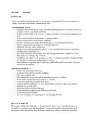
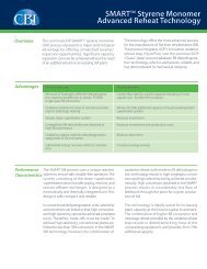
CondensersCondensersTop PATop PAKeroseneproductKerosenePAKerosenePAKeroseneproductDieselproductAGOproductDieselPAVery lowreflux rateAGO PADieselPAHigh refluxRemove PAHigher dieselproduct yieldMorefractionationtraysLoweroverflashCrudechargeLow efficiencylow strtippingsteamCrudechargeImprovedefficiencyHigherstripping steamHigh amountof 200-316ºChydrocarbonVery low amountof 200-316ºChydrocarbonFigure 2 Crude tower pumparoundstube side has no dead areas andcan be effectively water washed.A top pumparound can be addedto further reduce the amount ofhigh-risk surface area in the <strong>crude</strong>overhead system. This is especiallyimportant with heavy Canadian<strong>crude</strong> processing. Without a toppumparound all of the reflux forthe top tray must be condensed inthe <strong>crude</strong> overhead <strong>exchanger</strong>s.With a top pumparound to supplythe reflux the <strong>crude</strong> overhead<strong>exchanger</strong>s will only condense theproduct. To be effective, the toppumparound return temperaturemust be high enough to avoidsublimation of amine salts andwater condensation in the top ofthe <strong>crude</strong> tower.Crude column pumparound andproduct streams can be drawn fromthe same location or from differentlocations in the column. Forexample, some designers will drawdiesel product and diesel pumparoundfrom different locations.While this provides some benefits indraw temperature, it can adverselyaffect fractionation. Low liquid rateson fractionation trays can ultimatelylead to product draws that dry outat certain conditions, resulting inunstable operation. When thisoccurs, as it frequently does, thebenefits of split draw are diminished.Crude <strong>unit</strong>s designed toprocess a wide range or variable<strong>crude</strong> blends should draw productand pumparound from the samelocation in the column.Atmospheric gas oil (AGO)pumparounds (see Figure 2) areonly warranted when the <strong>crude</strong>blend is light enough to generatehigh lift in the <strong>crude</strong> tower andthen provide sufficient refluxbetween diesel and AGO productfor good fractionation. If an AGOpumparound is used with heavy<strong>crude</strong>, the diesel/AGO productfractionation is poor, resulting inexcessive diesel boiling range materialin the AGO product. However,this is often overlooked in favour ofthe high draw temperature associatedwith AGO pumparounds.Most vacuum towers are designedwith light (LVGO) and heavyvacuum gas oil (HVGO) products,which sets the amount of <strong>heat</strong> availableat a given temperature level.Two-product vacuum towersproduce draw temperatures ofapproximately 145°C and 270°C forLVGO and HVGO streams, respectively.Most, if not all, of thelow-level LVGO pumparound <strong>heat</strong>is lost to air or cooling water becausethere are not many <strong>heat</strong> sinks for thelow draw temperature. HVGO product<strong>heat</strong> can be recovered into <strong>crude</strong>,waste <strong>heat</strong> steam generation or toreboil light ends towers. Therequired HVGO pumparound rate6 Sour & Heavy 2012 www.eptq.com
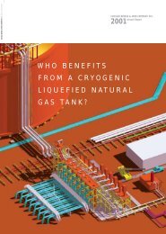
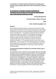
CWCWCrude250ºC270ºCCrudeCrude320ºCReduced<strong>crude</strong>Reduced<strong>crude</strong>Figure 3 Vacuum tower MVGO pumparoundand <strong>exchanger</strong> surface area are typicallyvery high with two productvacuum towers due to a relativelylow temperature and high duty.Adding medium vacuum gas oil(MVGO) product produces threetemperature levels (see Figure 3),minimises <strong>heat</strong> loss to air andwater, maximises the <strong>heat</strong> recoveredinto <strong>crude</strong> pre<strong>heat</strong>, andreduces the overall surface area.MVGO and HVGO pumparoundstreams are approximately 250°Cand 320°C, respectively, dependingon the product split betweenMVGO and HVGO. The higherHVGO draw temperature reducesthe number of <strong>exchanger</strong> shells andsurface area compared to only anHVGO pumparound.Figure 4 shows a fully optimisedvacuum tower producing diesel,LVGO, MVGO and HVGO productstreams. This maximises theproduction of high-value dieselboiling range material from theCDU/VDU and optimises both theMVGO and HVGO pumparounddraw temperature for a givenamount of recoverable <strong>heat</strong>.Drawing LVGO product from thebottom of the fractionation bedfurther increases the MVGO drawtemperature, reducing the capitaland operating costs to recover it.Low-fouling designFouling is a layer that accumulateson the inside and outside of thetubes, reducing <strong>heat</strong> transfer. Thehigher the fouling resistance, thelower the <strong>heat</strong> transfer. The foulingresistance can be between 50-85%of the total resistance for a heavilyfouled <strong>exchanger</strong>. To compensatefor high fouling, more area isneeded; however, adding more areacan be counterproductive because itgenerally results in lower velocityand higher fouling.Crude pre<strong>heat</strong> <strong>exchanger</strong>s can besusceptible to very high fouling.Fouling factors as high as 0.01hr-m 2 -°C/Kcal have been backcalculatedfrom operating data.Exchanger design and selection areimportant and can have a significantimpact on fouling. Lowvelocity designs result in high fouling,even for light <strong>crude</strong>s. Awww.eptq.com Sour & Heavy 2012 7
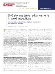
FeedStrippingsteamFigure 4 Optimised four product vacuum towerproperly designed <strong>exchanger</strong> withhigh tube- and shell-side velocitieswill minimise fouling. Certainheavy <strong>crude</strong> oils are incompatiblewhen mixed together, causingasphaltenes to precipitate. These<strong>crude</strong> oils are highly unstable, so itis very important to design the<strong>exchanger</strong>s for high velocity.Exchanger design guidelinesThe designer cannot control the<strong>crude</strong> fouling tendency, only the<strong>exchanger</strong> design and <strong>exchanger</strong>type. For new designs, <strong>exchanger</strong>scan be designed with high velocityand reasonably low fouling factors,which results in a minimal excesssurface area. However, for revamps,it is not always possible to rectifyall low-velocity designs andCrudeCrudeCrudeCrudeEjectorsDieselLVGOMVGOHVGOVacuum towerbottomsrealistic fouling factors must bedetermined from actual plant dataso that future performance can bepredicted.VelocityLow tube velocities result in highfouling. To minimise fouling, velocitiesare ideally kept above 2.4 m/sand sometimes higher on the tubeside and between 1.2-2.4 m/s onthe shell side. High shell-side velocitiesare achievable with advancedbundle designs, such as that of theHelixChanger <strong>heat</strong> <strong>exchanger</strong>,whereas a high shell-side velocity isnot practical with standard segmentalbaffles.For a new design, when <strong>crude</strong> isplaced on the tube side, a two-pass<strong>exchanger</strong> with 1in tubes should beused. The number of tubes neededto obtain 2.4 m/s sets the shell’sinside diameter. The length of the<strong>exchanger</strong> or number of shells isadjusted to meet surface arearequirements. Increasing the shell’sinside diameter and the number oftubes to meet the surface arearequirements reduces the tube- andshell-side velocities and increasesfouling. Designers will sometimesenlarge the shell’s inside diameterto reduce the number of shells toreduce costs. However, this designresults in lower velocity, more foulingand higher lifecycle costs thatare greater than the originalsavings.For a new design, a 1in tube withtwo passes minimises the pressuredrop. A typical two-pass <strong>crude</strong><strong>exchanger</strong> with <strong>crude</strong> on the tubeside at 2.4 m/s will have less than0.7 kg/cm 2 pressure drop per shell.One-inch tubes are preferred over0.75in tubes because the pressuredrop per metre of tube is lower atthe same velocity.For grassroots <strong>crude</strong> <strong>unit</strong>s, a lowfoulingdesign can be incorporatedinto the pump head specifications.In revamps, <strong>exchanger</strong> velocitiesare often limited by existing pumpsize, pipe flange ratings and<strong>exchanger</strong> design pressure. Pumpsystem hydraulics must be evaluatedcarefully for each circuit todetermine opport<strong>unit</strong>ies to increasevelocity and reduce fouling. A lowfouling design is not always possiblein a revamp because of existingconstraints.Shell-side velocity is limited bythe bundle’s inside diameter, andbaffle geometry and spacing. Forexample, velocities much higherthan 0.62 m/s are not practical in asegmental baffled <strong>exchanger</strong>. Toincrease shell-side velocity, bafflespacing and cut must be reduced.A higher pressure drop generallyincreases flow in the leakage andbypass areas of the bundle. Poorlymatched baffle spacing and cuts canalso lead to large eddies and “dead”zones.Advanced baffle designs such asthat used in the LummusTechnology HelixChanger designuse quadrant-shaped baffles at anangle to create a helical flow pattern8 Sour & Heavy 2012 www.eptq.com
through the bundle. This flowpattern reduces dead areas andresults in a lower pressure drop forthe same velocity compared with asegmental baffled <strong>exchanger</strong>. Thebenefit is that the shell-side velocitycan be designed for 1.5-2.48 m/s.Crude pre<strong>heat</strong> <strong>exchanger</strong>s designedwith high velocity on both the shelland tube side of a HelixChangerhave demonstrated extremely lowfouling in heavy <strong>crude</strong> service.Is the pressure drop really lower?Fouling begins as soon as an<strong>exchanger</strong> starts up and continuesuntil the terminal velocity isreached. After the terminal velocityis reached, fouling continues but ata much slower rate. Low-velocity<strong>exchanger</strong>s foul rapidly, sometimesreaching the asymptotic foulinglevel within the first 6-12 months ofoperation. However, most <strong>crude</strong><strong>unit</strong>s are being operated for four tosix years between planned turnarounds.A fouled pressure drop issignificantly higher than a cleanpressure drop for low-velocity<strong>exchanger</strong>s. It is not uncommon forthe fouled pressure drop to be twoto three times higher than the cleanpressure drop.An <strong>exchanger</strong> designed for highvelocity results in a higher initialclean pressure drop. However, ahigh-velocity <strong>exchanger</strong>’s fouledpressure drop is less than 1.5 timesthe clean pressure drop. So, doesdesigning a low velocity reallyresult in less pressure drop?This is especially true for <strong>crude</strong>pre<strong>heat</strong> trains with multiple<strong>exchanger</strong>s in series. <strong>Designing</strong> forhigh velocity will appear to add topumping costs at first; however,this is not necessarily true afterfactoring in the significantly higherfouled pressure drop of the lowvelocitydesign. The problem is thatthere is no way to calculate fouledpressure drop. Most designers donot get feedback from their designsand they do not go to the field tomeasure pressure drop. If they did,they would appreciate the differencesin fouled pressure dropbetween a low-velocity and highvelocitydesign.It is slowly becoming acceptedthat a high-velocity (high shearFigure 5 HelixChanger tube bundle in fabricationstress) design is the main variableneeded to produce a low-foulingdesign; however, there is still reluctanceto specify <strong>exchanger</strong>s thisway because of a higher initial pressuredrop and corresponding higherpumping costs. What is notnormally factored in is the fuelcosts of a low-velocity, high-foulingdesign, not to mention the highermaintenance costs associated withmore frequent cleanings.HelixChanger <strong>heat</strong> <strong>exchanger</strong>advantageThe inherent deficiencies of conventionalsegmental baffle shell-and-tube<strong>exchanger</strong>s are widely understood.The key deficiencies are:• The shell-side region is compartmentalised.Pressure energy iswasted in expansions, contractionsand turnarounds in multiple bendsrather than in generating <strong>heat</strong> transfer.The pressure gradient acrossthe baffles drives a significantamount of flow through the tubeto-baffleand shell-to-baffleclearances that escapes <strong>heat</strong> transfer.The result is inefficientconversion of shell-side pressuredrop to <strong>heat</strong> transfer• The flow leakage streams distortthe temperature profile, reducingthe effective mean temperaturedifference (MTD) for <strong>heat</strong> transfer• The perpendicular baffles encouragedead spots or recirculationzones where fouling or corrosioncould occur.The HelixChanger design removesmost of the above deficiencies.Courtesy: Lummus Technology Heat TransferQuadrant-shaped baffle segments,arranged at an angle to the tubeaxis in a sequential pattern, guidethe shell-side fluid in a helical paththrough the tube bundle. Figure 5shows a tube bundle in fabrication.The baffle segments serve as guidevanes without any compartmentalisation,and the flow traverses onboth sides of the baffles. The helicalflow path through the bundleprovides the necessary characteristicsto reduce flow dispersion andgenerate near plug-flow conditions,resulting in high thermal effectiveness.It ensures a certain amount ofcross-flow to the tubes to achievehigh <strong>heat</strong> transfer coefficients.Uniform flow velocities areachieved through the tube bundle,and the smooth helical flow eliminatesunnecessary pressure lossesin the <strong>exchanger</strong>. There is alsonegligible dead volume in the helicalshell space.Reduced fouling characteristicsThe design offers reduced foulingcharacteristics for the followingreasons:• There are few dead spaces withinthe helical shell space• The helical flow velocitiesachieved are significantly higher(1.5-3 times higher) than the averagecross-flow velocities achievedin equivalent segmental baffledesigns. Thus, the shear forcesacting on the tube wall are significantlyhigher in the HelixChangerdesigns• Uniform flow velocities throughwww.eptq.com Sour & Heavy 2012 9
pipelines, is also required.<strong>Designing</strong> for high velocity andusing advanced <strong>exchanger</strong> technologyhas proven that low-foulingdesigns are possible (see Figure 6).HELIXCHANGER is a mark of LummusTechnology Heat Transfer.Figure 6 HelixChanger bundle after two years of operation in hot <strong>crude</strong> vs hot resid servicethe tube-bundle are achieved due tothe relatively constant helical flowarea. This also translates into moreuniform tube-wall temperatures.ConclusionPre<strong>heat</strong> train design for heavyCanadian <strong>crude</strong>s can be verychallenging. Different requirementssuch as the need to vary desaltertemperature dictate a differentapproach not normally requiredwith other <strong>crude</strong>s. A well-conceiveddesign, with the flexibility to handlethe variable composition of diluentsbeing used to transport the <strong>crude</strong> inTony Barletta is a Chemical Engineer withProcess Consulting Services, Inc, in Houston,Texas. His primary responsibilities areconceptual process design and process designpackages for large capital revamps.Email: tbarletta@revamps.comSteve White is a Chemical Engineer withProcess Consulting Services, Inc, in Houston,Texas. He has more than 30 years of processdesign experience for refinery revamps andgrassroots <strong>unit</strong>s. Email: swhite@revamps.comKris Chunangad is Director of Heat Exchangersat Lummus Technology Heat Transfer, a CB&Icompany in Bloomfield, New Jersey. He hasmore than 18 years of experience in the designand development of advanced <strong>heat</strong> <strong>exchanger</strong>equipment, as well as their specialisedapplication in the oil and gas, refining,petrochemical and chemical industries.Email: kchunangad@cbi.comHELICAL BAFFLES AND hiTRAN TUBESIDEENHANCEMENT REDUCES CRUDE SHELLAND TUBE COUNT FROM 9 TO 2 ON FPSOImage courtesy of Total. - Gonsalez Thierry<strong>Designing</strong> in partnership, Calgavin and Lummus Technologydeliver high performance compact shell and tube <strong>exchanger</strong>sreducing weight from 400 tonnes to just 130 tonnes.Challenged with minimum space requirement and maximumefficiency, the 2x 4MW <strong>exchanger</strong>s operate at 8x tube-side<strong>heat</strong> transfer co-efficient and deliver long run times throughminimal fouling.CONVENTIONALSHELL AND TUBECOMPACT, ENHANCEDSHELL AND TUBE‘HELI-TRAN’EXCHANGERSPLAIN / SINGLESEGMENTAL BAFFLEhiTRAN /HELICAL BAFFLEGAINOHTC [W/m 2 k] 59.9 242.7 4XTUBE SIDEHTC [W/m 2 k] 95 770 8XDP [bar] (ALLOWED 1.50) 1.40 1.50 -SHELL SIDEHTC [W/m 2 k] 455 789 ~ 2DP [bar] (ALLOWED 1.50) 1.50 1.25 -GEOMETRYTOTAL NO. OF SHELLS [-] 9 2 -7TOTAL HT AREA [m 2 ] 6420 1704 ~ 1/4PLOT SPACE [m 2 ] 104.5 26.2 ~ 1/4WEIGHT WET [kg] 401148 130716 ~ 1/3EXCHANGER COSTS [%] 100 35 ~ 1/3RESEARCH. EVALUATION. INNOVATION. SOLUTION.talk to our engineers +44 (0) 1789 40040110 Sour & Heavy 2012 www.eptq.com